
Related Manuals for Canon DADF-AG1


Summary of Contents for Canon DADF-AG1
- Page 1 February 27, 2012 Revision 0 DADF-AG1 Service Manual Product Outline Technology Periodic Servicing Parts Replacement and Cleaning Procedure Adjustment Installation Appendix...
- Page 2 Canon will release technical information as the need arises. In the event of major not be copied, reproduced or translated into another language, in whole or in part, without the changes in the contents of this manual over a long or short period, Canon will issue a new consent of Canon Inc.
- Page 3 Explanation of Symbols The following rules apply throughout this Service Manual: The following symbols are used throughout this Service Manual. Each chapter contains sections explaining the purpose of specific functions and the relationship between electrical and mechanical systems with reference to the timing of Symbols Explanation Symbols...
- Page 4 Blank Page...
-
Page 5: Table Of Contents
Contents Basic Operation ----------------------------------------------------------------------------2-10 Release Operation ------------------------------------------------------------------------ 2-11 Detecting Jams -------------------------------------------------------------------- 2-11 Jams ------------------------------------------------------------------------------------------ 2-11 Power Supply ----------------------------------------------------------------------2-12 Power Supply -------------------------------------------------------------------------------2-12 Safety Precautions Stamp Operation ------------------------------------------------------------------2-12 Notes Before it Works Serving ---------------------------------------------0-9 Outline ----------------------------------------------------------------------------------------2-12 Points to Note at Cleaning --------------------------------------------------0-9 Fan -----------------------------------------------------------------------------------2-13 Fan Operation ------------------------------------------------------------------------------2-13 Product Outline... - Page 6 Clutch Solenoid Motor Fan PCB (DADF) ----------------------------- 4-10 Adjusting the Magnification ------------------------------------------------------ 5-9 Removing the ADF Motor(M1) -------------------------------------------------4-10 Adjusting the White Level -------------------------------------------------------- 5-9 Removing the Release Motor(M2) --------------------------------------------4-10 Installation Removing the Pressurization Solenoid(SL1) ------------------------------ 4-11 Pickup Clutch/Registration Clutch(CL1/CL2) ------------------------------ 4-11 How to Utilize This Installation Procedure ------------------------------6-2 Removing the ADF Driver PCB ------------------------------------------------4-12 When using the parts included in the package ----------------------------- 6-2...
-
Page 7: Safety Precautions
Safety Precautions ■ Notes Before it Works Serving ■ Points to Note at Cleaning... -
Page 8: Notes Before It Works Serving
Safety Precautions > Points to Note at Cleaning Notes Before it Works Serving CAUTION: At servicing, be sure to turn off the power source according to the specified steps and disconnect the power plug. CAUTION: Do not turn off the power switch when downloading is under way. Turning off the main power switch while downloading is under way can disable the machine. -
Page 9: Product Outline
Product Outline ■ Features (DADF) ■ Specifications (DADF) ■ Names of Parts (DADF) Product Outline... -
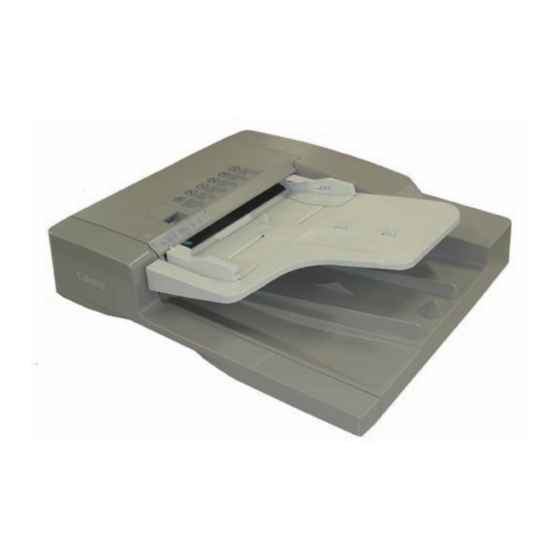
Page 10: External View
Product Outline > Names of Parts (DADF) > Cross Section Features (DADF) Names of Parts (DADF) The mixed mode of the different width manuscript. External View The detection of the different manuscript type (AB type / inch type). Slide guide Feeder Cover Specifications (DADF) Rear Cover... -
Page 11: Technology
Technology ■ Basic Configuration (DADF) ■ Controls (DADF) ■ Work of service (DADF) Technology... -
Page 12: Component Configuration
Technology > Basic Configuration (DADF) > Drive Configuration Basic Configuration (DADF) Drive Configuration Component Configuration ■ Outline of Electric Circuits Electric circuits of this machine are controlled by the main controller PCB2. The main controller PCB2 detect the input signals from sensors to output the signals that drive DC loads such as motors, solenoids, clutches, and fans at the predetermined timings. -
Page 13: Sensor Layout
Technology > Basic Configuration (DADF) > Outline of Operation Modes > Forward Pickup/Delivery Operation ■ Sensor Layout ■ Forward Pickup/Delivery Operation • Simplex read operation (when two document sheets are placed) SR11 PS1/PS2 NOTE: This operation is performed for all single-sided documents irrespective of whether document widths are the same or different. -
Page 14: Forward Pickup/Reverse Delivery Operation
Technology > Basic Configuration (DADF) > Outline of Operation Modes > Forward Pickup/Reverse Delivery Operation ■ Forward Pickup/Reverse Delivery Operation Duplex read operation (when two document sheets are placed) NOTE: This operation is performed for all double-sided documents irrespective of whether document widths are the same or different. - Page 15 Technology > Basic Configuration (DADF) > Outline of Operation Modes > Forward Pickup/Reverse Delivery Operation Stop after feeding the first Removal of registration loop of End of reading of front side Start of separation of second document sheet to reversal reverse side of first document of second document sheet document sheet and pressurization...
-
Page 16: Controls (Dadf)
Technology > Controls (DADF) > Document Detection > Outline Controls (DADF) Document Detection ■ Outline This machine detects a document using either of the two methods depending on the print mode. Removal of idle reversal registration Start of reading of reverse •... -
Page 17: Initial Document Size Detection
Technology > Controls (DADF) > Document Detection > Initial Document Size Detection ■ Initial Document Size Detection The following table shows the relationship among length detection sensor signals, document widths, and initial document sizes. The document length sensor 1 (SR7) and document length sensor 2 (SR10) detect the Document width detection Document length Detected size... -
Page 18: Document Pickup/Separation
Technology > Controls (DADF) > Document Pickup/Separation > Basic Pickup Operation Document Pickup/Separation Feed The pickup/feed motor (M1) turns in the reverse direction to drive the registration clutch (CL2), ■ Basic Pickup Operation thus allowing the registration roller to feed the document. The read roller feeds the document to the read wait point. -
Page 19: Pickup Unit And Stopper
Technology > Controls (DADF) > Document Reversing > Basic Operation Document Reversing ■ Pickup Unit and Stopper The pickup unit consists of a pickup roller and feed roller. ■ Basic Operation When the print start key is pressed or a document pickup signal is input, the pickup/feed motor (M1) turns in the reverse direction to lower the pickup unit via the pickup clutch (CL1), There are two types of document reversal operation: one that is performed from the top to the turning the pickup roller and feed roller to feed the document. -
Page 20: Document Feeding/Delivery
Technology > Controls (DADF) > Document Feeding/Delivery > Basic Operation 2-10 Document Feeding/Delivery Reversal/feed 1 When the trailing edge of the fed document moves past the delivery reversal sensor (SR3), ■ Basic Operation the pickup/feed motor stops. Immediately after this, the pickup/feed motor starts turning in the reverse direction to feed the document to the registration roller, then it stops. -
Page 21: Release Operation
Technology > Controls (DADF) > Detecting Jams > Jams 2-11 Detecting Jams ■ Release Operation When a document is read, the read roller 1 (lower driven rollers) are pressurized/released to ■ Jams prevent the training edge of the document from swaying. This machine detects document jams using the sensors shown below. -
Page 22: Power Supply
Technology > Controls (DADF) > Stamp Operation > Outline 2-12 Stamp Operation ACC ID JAM Code JAM Type Sensor Name Sensor ID 0003 DELAY Registration sensor ■ Outline 0004 STNRY Registration sensor 0005 DELAY Read sensor If the stamp function is selected in the FAX mode of the host machine, the stamp solenoid 0006 STNRY Read sensor... -
Page 23: Fan
Technology > Controls (DADF) > Fan > Fan Operation 2-13 ■ Fan Operation The fan (FM1) mounted on this machine always operates at full speed from the time ADF starts to feed paper until paper delivery is completed and exhausts the heat emitted by the ADF driver PCB and pickup/feed motor (M1). -
Page 24: Work Of Service (Dadf)
Technology > Work of service (DADF) > Periodic Servicing 2-14 Work of service (DADF) Periodic Servicing When the parts are reaching the expected service life, perform the parts replacement or When replacing the parts cleaning etc if needed. Item Part name Expected Operation This machine has the following adjustment items. - Page 25 Periodic Servicing ■ List of Work for Scheduled Servicing Periodic Servicing...
-
Page 26: Periodic Servicing List Of Work For Scheduled Servicing
Periodic Servicing > List of Work for Scheduled Servicing List of Work for Scheduled Servicing As for the user maintenance point as well, clean it at the time of the periodic maintenance. PR:Replacement (Periodically replaced parts) CR:Replacement (consumable parts) CL:Cleaning LU:Lubrication AD:Adjustment CH:Maintenance As of Nov 2011 Part name Part number... -
Page 27: Parts Replacement And Cleaning Procedure
Parts Replacement and Cleaning Procedure ■ List of Parts (DADF) ■ External Covers (DADF) ■ Main Units (DADF) ■ Consumable Parts Requiring Periodic Replacement and Cleaning Points (DADF) ■ Clutch Solenoid Motor Fan PCB (DADF) Parts Replacement and Cleaning Procedure... -
Page 28: External Covers
Parts Replacement and Cleaning Procedure > List of Parts (DADF) > Consumable Parts Requiring Periodic Replacement and Cleaning Points List of Parts (DADF) Consumable Parts Requiring Periodic Replacement and Cleaning Points External Covers Rear cover Feeder cover Front cover F-4-1 Part name Part number Reference... -
Page 29: List Of Clutchs, Solenoids, Motors, Fans, Pcbs
Parts Replacement and Cleaning Procedure > List of Parts (DADF) > List of Sensors List of Clutchs, Solenoids, Motors, Fans, PCBs List of Sensors PCB1 SR10 PCB3 SR11 F-4-3 F-4-4 Part name Part number Reference Part name Part number Reference ADF motor Refer to page 4-10 Registration sensor... -
Page 30: External Covers (Dadf)
Parts Replacement and Cleaning Procedure > External Covers (DADF) > Removing the Rear Cover External Covers (DADF) 4) Detach the front cover. - Screw 2 pcs. Removing the Front Cover 1) Open the feeder cover. F-4-7 Removing the Rear Cover F-4-5 1) Open the feeder cover. -
Page 31: Removing The Feeder Cover
Parts Replacement and Cleaning Procedure > External Covers (DADF) > Removing the Feeder Cover Removing the Feeder Cover 1) Open the feeder cover. 2) Open the DADF. 3) Detach the front cover."Removing the Front Cover"(page 4-4). 4) Close the DADF. 5) Remove the feeder cover. -
Page 32: Main Units (Dadf)
Parts Replacement and Cleaning Procedure > Main Units (DADF) > Removing the Feed Unit Main Units (DADF) • 11) Remove the harness guide. - Connector 5 pcs. - Screw 1 pcs. Removing the Feed Unit 1) Remove the DADF from the host machine. 2) Open the feeder cover. -
Page 33: Consumable Parts Requiring Periodic Replacement And Cleaning Points (Dadf)
Parts Replacement and Cleaning Procedure > Consumable Parts Requiring Periodic Replacement and Cleaning Points (DADF) > Removing the Pickup Roller Unit Consumable Parts Requiring Periodic Replacement 3)Remove the pickup roller unit . - Resin ring , 2 pcs. and Cleaning Points (DADF) - Bearing , 2 pcs. -
Page 34: Removing The Separation Pad
Parts Replacement and Cleaning Procedure > Consumable Parts Requiring Periodic Replacement and Cleaning Points (DADF) > Replacing the Stamp Removing the Separation Pad Replacing the Stamp 1)Open the feeder cover. 1)Open the feeder cover and separation guide. 2) Using tweezers, remove the stamp 3)Using tweezers or the like, attach a new stamp. -
Page 35: Exchanging The Feed Guide
Parts Replacement and Cleaning Procedure > Consumable Parts Requiring Periodic Replacement and Cleaning Points (DADF) > Exchanging the Feed Guide Exchanging the Feed Guide 1) Open the DADF. 2) Remove the feed guide . -Screw , 2 pcs. F-4-19 3) Pell off the release paper of the new feed guide. 4) Attach the new feed guide. -
Page 36: Clutch Solenoid Motor Fan Pcb (Dadf)
Parts Replacement and Cleaning Procedure > Clutch Solenoid Motor Fan PCB (DADF) > Removing the Release Motor(M2) 4-10 Clutch Solenoid Motor Fan PCB (DADF) Removing the Release Motor(M2) 1) Open the feeder cover. Removing the ADF Motor(M1) 2) Open the DADF. 3) Detach the front cover."Removing the Front Cover"(page 4-4). -
Page 37: Removing The Pressurization Solenoid(Sl1)
Parts Replacement and Cleaning Procedure > Clutch Solenoid Motor Fan PCB (DADF) > Pickup Clutch/Registration Clutch(CL1/CL2) 4-11 Removing the Pressurization Solenoid(SL1) Pickup Clutch/Registration Clutch(CL1/CL2) 1) Open the feeder cover. 1) Open the feeder cover. 2) Remove the rear cover."Removing the Rear Cover"(page 4-4). 2) Remove the rear cover."Removing the Rear Cover"(page 4-4). -
Page 38: Removing The Adf Driver Pcb
Parts Replacement and Cleaning Procedure > Clutch Solenoid Motor Fan PCB (DADF) > Removing the ADF Driver PCB 4-12 Removing the ADF Driver PCB 4) Remove the clutch - Resin ring 1 pc 1) Open the feeder cover. - Bearing 1 pc 2) Remove the rear cover."Removing the Rear Cover"(page 4-4). -
Page 39: Removing The Led Pcb
Parts Replacement and Cleaning Procedure > Clutch Solenoid Motor Fan PCB (DADF) > Removing the Fan 4-13 Removing the LED PCB Removing the Fan 1) Open the feeder cover. 1) Open the feeder cover. 2) Open the DADF. 2) Remove the rear cover."Removing the Rear Cover"(page 4-4). -
Page 40: Removing The Sensor(Sr1,Sr2,Sr3)
Parts Replacement and Cleaning Procedure > Clutch Solenoid Motor Fan PCB (DADF) > Removing the Sensor(SR1,SR2,SR3) 4-14 Removing the Sensor(SR1,SR2,SR3) 8) Remove the document tray. - Connector 1 pc 1) Remove the DADF from the host machine. - Screw 1 pc - Screw 2 pcs. - Page 41 Parts Replacement and Cleaning Procedure > Clutch Solenoid Motor Fan PCB (DADF) > Removing the Sensor(SR1,SR2,SR3) 4-15 12) Remove the pickup clutch/registration clutch support base."Pickup Clutch/Registration 16) Remove the resin ring, pulley, gear, E-ring, and bearing. Clutch(CL1/CL2)"(page 4-11). 13) Remove the feed unit."Removing the Feed Unit"(page 4-6).
- Page 42 Parts Replacement and Cleaning Procedure > Clutch Solenoid Motor Fan PCB (DADF) > Removing the Sensor(SR1,SR2,SR3) 4-16 18) While pushing the hook in the direction of the arrow, remove the platen roller unit in the 19) Detach the cover direction of the arrow. - Screw 2 pcs.
- Page 43 Parts Replacement and Cleaning Procedure > Clutch Solenoid Motor Fan PCB (DADF) > Removing the Sensor(SR1,SR2,SR3) 4-17 20) Remove the read roller 2 21) Remove the sensor mount - Resin ring 1 pc. - Hook 2 pcs. - Pulley 1 pc. - Screw 2 pcs.
-
Page 44: Removing The Timing Sensor(Sr4)
Parts Replacement and Cleaning Procedure > Clutch Solenoid Motor Fan PCB (DADF) > Removing the Cover Open/Closed Sensor(SR6) 4-18 Removing the Timing Sensor(SR4) Removing the Cover Open/Closed Sensor(SR6) 1) Open the feeder cover. 1) Open the feeder cover. 2) Remove the rear cover."Removing the Rear Cover"(page 4-4). -
Page 45: Removing The Document Length Sensor(Sr7,Sr10)
Parts Replacement and Cleaning Procedure > Clutch Solenoid Motor Fan PCB (DADF) > Removing the A4R/LTRR Identification Senso(SR8) 4-19 Removing the Document Length Sensor(SR7,SR10) Removing the A4R/LTRR Identification Senso(SR8) 1) Detach the cover on the reverse side of the document tray. 1) Detach the cover on the reverse side of the document tray.(Refer to page 4-19) - Screw 3 pcs. -
Page 46: Removing The Release Motor Hp Sensor(Sr11)
Parts Replacement and Cleaning Procedure > Clutch Solenoid Motor Fan PCB (DADF) > Removing the Document Width Volume(VR1) 4-20 Removing the Release Motor HP Sensor(SR11) Removing the Document Width Volume(VR1) 1) Open the feeder cover. 1) Detach the cover on the reverse side of the document tray.(Refer to page 4-19) 2) Open the DADF. -
Page 47: Adjustment
Adjustment ■ Overview (DADF) ■ Adjustment Method (DADF) Adjustment... - Page 48 Adjustment > Overview (DADF) > Outline Overview (DADF) Outline This machine has the following adjustment items. Carry out each adjustment after replacing the relevant parts. Adjustment type Parts to Remarks Reference replace Height adjustment Hinge Refer to page 5-3 Adjusting the Tray Width During installation only Refer to page 5-6 Perpendicularity adjustment...
-
Page 49: Preparation Or Creation Of Test Chart
Adjustment > Adjustment Method (DADF) > Adjusting the Height > Pre-check Adjustment Method (DADF) Adjusting the Height ■ Pre-check Preparation or Creation of Test Chart Check whether the front and rear document glass spacers provided under the bottom of the Prepare a test chart. -
Page 50: Checking The Left Hinge Height
Adjustment > Adjustment Method (DADF) > Adjusting the Height > Checking the left hinge height ■ Checking the left hinge height 3) Checking the front-left height of the DADF. Set paper against the protrusions of the stream reading glass in such a manner that the 1) Checking the rear-left height of the DADF. -
Page 51: Adjustment Procedure
Adjustment > Adjustment Method (DADF) > Adjusting the Height > Adjust the height of the right hinge ■ Adjustment Procedure ■ Check the height of the right hinge (When the front or rear side is floating) When the DADF is closed, the document hold sheet must be in contact with the 1) Adjust the left hinge height. -
Page 52: Adjusting The Tray Width
Adjustment > Adjustment Method (DADF) > Adjusting the Perpendicularity Adjusting the Tray Width Adjusting the Perpendicularity Load a test chart in the DADF to make a copy. NOTE: The result of this adjustment is retained on the reader controller PCB. NOTE: Assuch, unlike previous DADFs, you will need to make this adjustment at time of The test chart is printed on the back cover of the Installation Procedure (this manual). -
Page 53: Adjusting The Read Position
Adjustment > Adjustment Method (DADF) > Adjusting the Read Position Adjusting the Read Position Loosen the screw securing the right hinge. 1) Start service mode. 2) On the Service Mode screen, touch the following notations in sequence to bring up the Adjustment screen: (LV.1) COPIER >... -
Page 54: Adjusting The Horizontal Registration
Adjustment > Adjustment Method (DADF) > Adjusting the Trailing Edge Registration Adjusting the Horizontal Registration Adjusting the Trailing Edge Registration 1) Place the test chart in the DADF, and make a copy. 1) Place the Test Chart in the DADF, and make a copy. 2) Compare the copy against the Test Chart for the horizontal registration;... -
Page 55: Adjusting The Magnification
Adjustment > Adjustment Method (DADF) > Adjusting the White Level Adjusting the Magnification Adjusting the White Level 1) Place the Test Chart in the ADF, and make a copy. Refer to the output as copy A. NOTE: 2) Compare Test Chart and copy A in terms of the length of the image in feed direction; as This is a item of adjustment in which the white level of images made in stream reading necessary, make adjustments in service mode. - Page 56 Adjustment > Adjustment Method (DADF) > Adjusting the White Level 5-10 12) Remove the paper from the copyboard glass, and place it on the original tray of the DADF. 13) Press [DF-WLVL4] on the touch panel to highlight. 14) Press [OK]. - The machine executes auto adjustment (duplex stream reading).
-
Page 57: Installation
Installation ■ How to Utilize This Installation Procedure ■ Confirmation before the installation ■ Unpacking and Checking the Components ■ Installation Procedure ■ Adjustment Method (DADF) ■ Others Installation... -
Page 58: How To Utilize This Installation Procedure
Installation > How to Utilize This Installation Procedure > Symbols in the Illustration How to Utilize This Installation Procedure When using the parts included in the package A symbol is described on the illustration in the case of using the parts included in the package of this product. -
Page 59: Confirmation Before The Installation
Installation > Confirmation before the installation > Check Items when Turning OFF the Main Power Confirmation before the installation Check Items when Turning OFF the Main Power Check that the main power switch is OFF. 1) Turn OFF the main power switch of the host machine. 2) Be sure that Control Panel Display and Main Power Lamp are both turned OFF, and then disconnect the power plug. -
Page 60: Unpacking And Checking The Components
Installation > Unpacking and Checking the Components > Unpacking and Checking the Contents Unpacking and Checking the Components Unpacking and Checking the Contents 1) Make sure that none of the following parts is missing. DADF main unit 1unit Stepped screw (M4X10) 2pcs. -
Page 61: Installation Procedure
Installation > Installation Procedure > Installing the DADF Installation Procedure Installing the DADF 1) Remove packing materials and tapes from the DADF unit. 2) Peel off 2 pieces of face sticker (The face sticker which peel off is 4) Affix 2 pieces of the face stickers over the hinge holes. unnecessary). -
Page 62: Affixing Labels
Installation > Installation Procedure > Affixing Labels 7) Secure the hinges with the 2 stepped screws (M4X10). 8) Close the DADF. Secure the right hinge with the screw aligning the edge of the screw head with the mark-off line (long). 9) Detach the blind sheet and connect the cable of the DADF. -
Page 63: Others
Installation > Others > Cleaning the Stream Reading Glass Others Attaching the Hinge Covers 1) Attach the supplied 2 hinge covers. F-6-11 Cleaning the Stream Reading Glass 1) Open the DADF. 2) Hardly squeeze the cloth soaked with water. Using this cloth,wipe the stream reading glass clean. -
Page 64: Others
Installation > Others > Checking the Operation > Operation Check Others Checking the Operation ■ Operation Check Installing the Stamp(Option for ADF) 1) Check the following operations. 1) Open the paper feeder cover and jam handling cover. - Check the single-sided and double-sided copy operations. - If the machine has the stamp unit for the FAX,check the stamping operation in FAX mode. -
Page 65: Appendix
Appendix ■ Service Tools (DADF) ■ Signal Name List (DADF) ■ General Circuit Diagram (DADF) -
Page 66: Solvents And Oils
Appendix > Service Tools (DADF) Service Tools (DADF) ■ Solvents and Oils Name Uses Composition Remarks Alcohol Cleaning; e.g., Fluoride-family hydrocarbon Do not bring near fire. Glass, plastic, rubber, Alcohol Procure locally. external covers Surface activating agent Substitute: Water IPA (isopropyl alcohol) Solvent Cleaning;... -
Page 67: Signal Name List (Dadf)
Appendix > Signal Name List (DADF) Signal Name List (DADF) Jack No. Pin No. Abbreviated Signal Name Signal Name ■ Signal Name List RKMOT HP Release motor HP sensor signal Jack No. Pin No. Abbreviated Signal Name Signal Name STMP SOL Stamp solenoid signal REG_SEN Registration sensor signal... -
Page 68: General Circuit Diagram (Dadf)
General Circuit Diagram (DADF) General Circuit Diagram (1/1) Pickup Registration Release motor clutch clutch ADF Fan ADF motor Pressurization Delivery reversal Registration Document set solenoid Cover open/closed sensor sensor sensor sensor Read sensor Timing sensor J89H J112 J101 J102 J103 J104 J105 J106...