Table of Contents
Advertisement
Advertisement
Table of Contents

Related Manuals for Canon DADF-P1


Summary of Contents for Canon DADF-P1
- Page 1 Service Manual Feeder DADF-P1 Sep 14 2005...
- Page 3 Canon will release technical information as the need arises. In the event of major changes in the contents of this manual over a long or short period, Canon will issue a new edition of this manual.
- Page 4 Introduction Symbols Used This documentation uses the following symbols to indicate special information: Symbol Description Indicates an item of a non-specific nature, possibly classified as Note, Caution, or Warning. Indicates an item requiring care to avoid electric shocks. Indicates an item requiring care to avoid combustion (fire). Indicates an item prohibiting disassembly to avoid electric shocks or problems.
- Page 5 Introduction The following rules apply throughout this Service Manual: 1. Each chapter contains sections explaining the purpose of specific functions and the relationship between electrical and mechanical systems with refer- ence to the timing of operation. In the diagrams, represents the path of mechanical drive; where a signal name accompanies the symbol , the arrow indicates the direction of the electric signal.
-
Page 7: Table Of Contents
Contents Contents Chapter 1 Specifications 1.1 Product Specifications ........................... 1- 1 1.1.1 Specifications ............................1- 1 1.2 Names of Parts ............................... 1- 2 1.2.1 External View............................1- 2 1.2.2 Cross-section............................1- 2 Chapter 2 Functions 2.1 Basic Construction............................2- 1 2.1.1 Outline of Electric Circuit ........................ - Page 8 Contents 3.1.1 Feeder ................................ 3- 1 3.1.1.1 Removing from the Host Machine ....................3- 1 3.2 External Covers............................... 3- 1 3.2.1 Front Cover..............................3- 1 3.2.1.1 Removing the Front Cover ......................3- 1 3.2.2 Rear Cover ..............................3- 1 3.2.2.1 Removing the Rear Cover ....................... 3- 1 3.2.3 Feeder Cover ............................
- Page 9 Contents 3.4.5.5 Removing the Feed Motor....................... 3- 8 3.4.5.6 Removing the Timing Belt ....................... 3- 9 3.4.5.7 Removing the Document Tray ......................3- 9 3.4.5.8 Removing the Feeding Unit......................3- 9 3.4.5.9 Removing the Platen Roller Unit ....................3- 9 3.4.5.10 Removing the Read Roller 2.......................
- Page 10 Contents 3.4.9.8 Removing the Document Tray ...................... 3- 20 3.4.9.9 Removing the Feeding Unit ......................3- 20 3.4.9.10 Removing the Platen Roller......................3- 20 3.4.10 Delivery Reversing Roller (lower) ...................... 3- 21 3.4.10.1 Removing the Front Cover ......................3- 21 3.4.10.2 Removing the Feeder Cover .......................
- Page 11 Contents 3.5.4.2 Removing the Document Placement Sensor ................3- 30 3.5.5 Document Length sensor ........................3- 30 3.5.5.1 Removing the Document Length Sensor ..................3- 30 3.5.6 Pressurization Solenoid......................... 3- 31 3.5.6.1 Removing the Rear Cover......................3- 31 3.5.6.2 Removing the Pressurization Solenoid (Roller Release Solenoid)......... 3- 31 3.5.7 ADF Driver PCB .............................
-
Page 13: Chapter 1 Specifications
Chapter 1 Specifications... - Page 15 Contents Contents 1.1 Product Specifications............................1-1 1.1.1 Specifications .............................. 1-1 1.2 Names of Parts..............................1-2 1.2.1 External View.............................. 1-2 1.2.2 Cross-section ............................... 1-2...
-
Page 17: Product Specifications
Chapter 1 1.1 Product Specifications 1.1.1 Specifications 0010-3980 T-1-1 Item Specification Remarks Document pickup method Automatic pickup and delivery Document loading direction Face-up Document loading position Aligned to center Document separation method Upper separation Continuous feed: 52-105 g/m2 or less Document longer than 432 mm: 60-90 g/m2 Single feed: Less than 37-52 g/m2, 105-128 g/m2 or less... -
Page 18: Names Of Parts
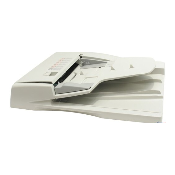
Chapter 1 1.2 Names of Parts 1.2.1 External View 0010-3981 F-1-1 T-1-2 [1] Feeder cover [4] Document pickup tray [2] Rear cover [5] Front cover [3] Slide guide [6] Document delivery tray 1.2.2 Cross-section 0010-3982 [1] [2] [3] [4] [5] [12] [15] [14]... -
Page 19: Chapter 2 Functions
Chapter 2 Functions... - Page 21 Contents Contents 2.1 Basic Construction ............................. 2-1 2.1.1 Outline of Electric Circuit ........................... 2-1 2.2 Basic Operation ..............................2-1 2.2.1 Drive Mechanism and Signals........................2-1 2.2.2 Outline of Operation Mode ......................... 2-2 2.2.3 Forward Pickup/Delivery (Single-sided document > Simplex Printing) Operation ........2-2 2.2.4 Forward Pickup/Reversal Delivery (Double-sided document >...
-
Page 23: Basic Construction
Chapter 2 2.1 Basic Construction 2.1.1 Outline of Electric Circuit 0010-3889 Electric circuits of this machine are controlled by the reader controller PCB and image processor PCB. The ASICs on the reader controller PCB and image processor PCB detect the signals received from the host machine to output the signals that drive DC loads such as motors and solenoids at the predetermined timings. The reader controller PCB and image processor PCB do not have a memory area;... -
Page 24: Outline Of Operation Mode
Chapter 2 [1] ADF driver PCB [2] Document detection signal [3] Document detection signal [4] Pickup motor drive signal [5] Document placement signal [6] Stamp solenoid drive signal [7] Document placement signal [8] Feed motor drive signal [9] Roller release solenoid drive signal [10] Last document detection signal [11] Paper size (width) identification signal 1 [12] Paper size (width) identification signal 2... - Page 25 Chapter 2 This operation is performed for all double-sided documents irrespective of whether document widths are the same or different. Document Feed Pickup Formation of loop Reversal Formation of loop Waiting for reading Waiting for reading Reading to next page F-2-4 Feed Reverse side reading...
-
Page 26: Document Detection
Chapter 2 2.3 Document Detection 2.3.1 Outline 0010-3898 This machine detects an document using either one of the two methods depending on the print mode. - Normal print mode (other than mixed size print mode and banner paper mode) - Mixed size print mode and banner paper mode a. -
Page 27: Initial Document Size Detection
Chapter 2 ADF driver PCB Detection lever Document PI11 F-2-7 2.3.4 Initial Document Size Detection 0010-3901 The document length sensor 1 (PI4) and document length detection sensor 2 (PI5) detect the longitudinal size of the document placed on the document tray, and the document width sensor 1 (PI2) and document width sensor 2 (PI1) detect the lateral size of the document. -
Page 28: Document Pickup/Separation
Chapter 2 T-2-6 Sensor name Document width Document width Document length Document length sensor 1 sensor 2 sensor 1 sensor 2 11 x 17 Size LTRR STMT 2.4 Document Pickup/Separation 2.4.1 Basic Pickup Operation 0011-2263 With an document placed on the document tray, pressing the print start key will picks up the document in the following manner. a. -
Page 29: Pickup Unit And Stopper
Chapter 2 Platen roller Read glass F-2-12 2.4.2 Pickup Unit and Stopper 0010-3908 The pickup unit consists of a pickup roller and separation roller. When the print start key is pressed or an document pickup signal is input, the pickup motor (M2) turns in the reverse direction to lower the pickup unit, turning the pickup roller and separation roller to feed the document. -
Page 30: Document Reversing
Chapter 2 +24V CN11 KMOT_A KMOT_A KMOT_A* KMOT_B Motor KMOT_A* driver KMOT_B* KMOT_B KMOT_IA KMOT_IB KMOT_B* Image Reader processor controller ADF driver PCB F-2-15 The pickup motor of the ADF is controlled by the image processor PCB. The image processor PCB outputs drive pulses to the pickup motor according to the selected print mode (magnification, operation mode, timing, etc.). -
Page 31: Operation Sequence
Chapter 2 Registration roller Delivery reversal roller Read roller Read standby point F-2-18 2.5.2 Operation Sequence 0010-3915 Start key ON document pickup signal input Document placement Document's Document Document Document reverse separation reversal reading side reading /feed Document set sensor (PI11) Registration paper sensor (PI8) Read sensor (PI7) -
Page 32: Operation Sequence
Chapter 2 2.6.2 Operation Sequence 0010-3917 Start key ON document pickup signal input Document placement Document Document reading Document delivery separation/feed Document set sensor (PI11) Registration paper sensor (PI8) Read sensor (PI7) Delivery reversal sensor (PI6) Loop formation Read standby Pickup motor (M2) Reverse rotation Feed motor (M1) -
Page 33: Power Supply
Chapter 2 PI6: Delivery reversal sensor PI7: Read sensor PI8: Registration paper sensor PI10: Cover open/close sensor PI11: Document set sensor 2.8 Power Supply 2.8.1 Power Supply 0010-3920 The power supply lines are shown below. This machine is powered via two power supply lines (24 V and 3.3 V) from the host machine. - Motor - Solenoid Host... - Page 34 Chapter 2 Start key ON document pickup signal input Document placement Document Document reading Document delivery separation/feed Document set sensor (PI11) Registration paper sensor (PI8) Read sensor (PI7) Delivery reversal sensor (PI6) Loop formation Read standby Pickup motor (M2) Reverse rotation Feed motor (M1) Forward rotation Roller release...
-
Page 35: Chapter 3 Parts Replacement Procedure
Chapter 3 Parts Replacement Procedure... - Page 37 Contents Contents 3.1 Removing from the Host Machine ........................3-1 3.1.1 Feeder ................................3-1 3.1.1.1 Removing from the Host Machine ....................... 3-1 3.2 External Covers ..............................3-1 3.2.1 Front Cover..............................3-1 3.2.1.1 Removing the Front Cover ........................3-1 3.2.2 Rear Cover..............................3-1 3.2.2.1 Removing the Rear Cover ........................
- Page 38 Contents 3.4.4.3 Removing the Upper Registration Roller ..................... 3-7 3.4.5 Lower Registration Roller ........................... 3-8 3.4.5.1 Removing the Front Cover ........................3-8 3.4.5.2 Removing the Feeder Cover ......................... 3-8 3.4.5.3 Removing the Rear Cover........................3-8 3.4.5.4 Removing the ADF Driver PCB......................3-8 3.4.5.5 Removing the Feed Motor ........................
- Page 39 Contents 3.4.9.2 Removing the Feeder Cover....................... 3-19 3.4.9.3 Removing the Rear Cover ........................3-19 3.4.9.4 Removing the ADF Driver PCB......................3-19 3.4.9.5 Removing the Pickup Motor ......................3-19 3.4.9.6 Removing the Feed Motor........................3-19 3.4.9.7 Removing the Timing Belt ......................... 3-19 3.4.9.8 Removing the Document Tray ......................
- Page 40 Contents 3.5.2.1 Removing the Relay PCB (Document Width Sensor PCB) ............... 3-29 3.5.3 Cover Open/Closed Sensor........................3-30 3.5.3.1 Removing the Rear Cover........................3-30 3.5.3.2 Removing the Feeder Cover Open/Close Sensor ................3-30 3.5.4 Document Set Sensor..........................3-30 3.5.4.1 Removing the Rear Cover........................3-30 3.5.4.2 Removing the Document Placement Sensor ..................
-
Page 41: Removing From The Host Machine
Chapter 3 3.1 Removing from the Host Machine 3.2 External Covers 3.1.1 Feeder 3.2.1 Front Cover 3.1.1.1 Removing from the Host Machine 3.2.1.1 Removing the Front Cover 0010-3922 0010-3923 1) Turn off the main power switch of the host machine. 1) Open the feeder cover [1], and then remove the screw [2]. -
Page 42: Removing The Feeder Cover
Chapter 3 F-3-7 2) Remove the two screws [3], and then detach the front cover [4]. F-3-10 Remove the rear cover with the two claws [3] released. 3.3.1.2 Removing the Pickup Motor 0010-3927 1) Disconnect the connector [1], and then remove the tension spring [2]. 2) Remove the two screws [3], and then remove the pickup motor [4] together with the adjusting plate. -
Page 43: Feed Motor
Chapter 3 3.3.2.3 Installing the Feed Motor 0010-3931 1) Install the feed motor in such a manner that the motor pulley is engaged with the timing belt, and then tighten two screws [1] temporarily. 2) Attach the tension spring [2] to the adjusting plate and motor base, and then securely tighten the screws tightened temporarily in step 1. -
Page 44: Removing The Rear Cover
Chapter 3 F-3-18 3.3.3.3 Removing the Rear Cover 0010-6192 1) Open the feeder cover. 2) Move to the back of the machine, remove the two screws [1], and then detach the rear cover [2]. F-3-21 3.3.3.6 Removing the Feed Motor 0010-6197 1) Disconnect the connector [1], and then remove the tension spring [2]. -
Page 45: Document Feeding System
Chapter 3 F-3-27 2) Remove the two screws [3], and then detach the front cover [4]. F-3-24 7) Remove the four screws [1], and then remove the metal plate. F-3-28 3.4.1.2 Removing the Feeder Cover 0010-6355 1) Remove the screw [1] and positioning pin [2], and then detach the feeder cover [3]. -
Page 46: Precaution About Pickup Roller Unit Installation
Chapter 3 F-3-31 F-3-34 3.4.1.4 Precaution about Pickup Roller Unit Installation 0010-3979 3.4.2.2 Removing the Feeder Cover 0010-6357 1) Remove the screw [1] and positioning pin [2], and then detach the feeder cover [3]. - Install the pickup roller unit with the stopper arm [1] at the front as shown below. -
Page 47: Separation Plate/Separation Pad
Chapter 3 F-3-41 2) Remove the two screws [3], and then detach the front cover [4]. F-3-38 2) Remove the pickup roller [1]. 3) Remove the E-ring [2], and then remove the separation roller [3]. F-3-42 3.4.4.2 Removing the Feeder Cover 0010-6360 1) Remove the screw [1] and positioning pin [2], and then detach the feeder cover [3]. -
Page 48: Lower Registration Roller
Chapter 3 3.4.5.3 Removing the Rear Cover 0010-6620 1) Open the feeder cover. 2) Move to the back of the machine, remove the two screws [1], and then detach the rear cover [2]. F-3-45 3.4.5 Lower Registration Roller 3.4.5.1 Removing the Front Cover 0010-6605 1) Open the feeder cover [1], and then remove the screw [2]. -
Page 49: Removing The Timing Belt
Chapter 3 3.4.5.6 Removing the Timing Belt 0010-6649 1) Remove the screw [1], and then disconnect the ground cable [2]. F-3-55 3.4.5.7 Removing the Document Tray 0010-6656 1) Remove the screw [1] at the front of the machine, and then remove the tray holder [2]. -
Page 50: Removing The Read Roller 2
Chapter 3 When installing the read roller 2, loosen the screws [6] and attach the belt. F-3-59 3) Remove the resin ring [1], belt [2], gear [3], and bearing [4]. 4) Remove the platen roller unit [5]. [3] [4] [6] F-3-63 3.4.5.11 Removing the Sensor Unit in the Feeder Unit 0010-6672... -
Page 51: Delivery Reversing Roller (Upper)
Chapter 3 3.4.6.2 Removing the Feeder Cover 0010-6618 1) Remove the screw [1] and positioning pin [2], and then detach the feeder cover [3]. F-3-70 3.4.6.3 Removing the Rear Cover 0010-6621 F-3-66 1) Open the feeder cover. 2) Move to the back of the machine, remove the two screws [1], and then 5) Remove the resin ring [1], and then remove the bearing [2] and lower reg- detach the rear cover [2]. -
Page 52: Removing The Feed Motor
Chapter 3 F-3-73 3.4.6.6 Removing the Feed Motor 0010-6643 1) Disconnect the connector [1], and then remove the tension spring [2]. 2) Remove the two screws [3], and then remove the feed motor [4] together with the adjusting plate. F-3-76 7) Remove the four screws [1], and then remove the metal plate. -
Page 53: Removing The Feeding Unit
Chapter 3 F-3-79 F-3-83 3.4.6.9 Removing the Feeding Unit 3.4.7 Read Roller 1 0010-6668 1) Remove the two screws [1]. 3.4.7.1 Removing the Front Cover 0010-6607 1) Open the feeder cover [1], and then remove the screw [2]. F-3-80 2) Remove the two screws [1], and then remove the feeding unit. F-3-84 2) Remove the two screws [3], and then detach the front cover [4]. -
Page 54: Removing The Rear Cover
Chapter 3 3.4.7.3 Removing the Rear Cover 3.4.7.6 Removing the Feed Motor 0010-6622 0010-6644 1) Open the feeder cover. 1) Disconnect the connector [1], and then remove the tension spring [2]. 2) Move to the back of the machine, remove the two screws [1], and then 2) Remove the two screws [3], and then remove the feed motor [4] together detach the rear cover [2]. -
Page 55: Removing The Document Tray
Chapter 3 F-3-95 3.4.7.9 Removing the Feeding Unit 0010-6667 1) Remove the two screws [1]. F-3-92 7) Remove the four screws [1], and then remove the metal plate. F-3-96 2) Remove the two screws [1], and then remove the feeding unit. F-3-93 8) Remove the timing belt [1]. -
Page 56: Read Roller 2
Chapter 3 cover [3]. F-3-103 F-3-99 4) Remove the two screws [1], two springs [2], the member [3], and the 3.4.8.3 Removing the Rear Cover member [4] and then remove the read roller 1 [5]. 0010-6623 1) Open the feeder cover. 2) Move to the back of the machine, remove the two screws [1], and then detach the rear cover [2]. -
Page 57: Removing The Feed Motor
Chapter 3 F-3-106 3.4.8.6 Removing the Feed Motor 0010-6645 1) Disconnect the connector [1], and then remove the tension spring [2]. 2) Remove the two screws [3], and then remove the feed motor [4] together with the adjusting plate. F-3-109 7) Remove the four screws [1], and then remove the metal plate. -
Page 58: Removing The Feeding Unit
Chapter 3 F-3-116 3) Remove the resin ring [1], belt [2], gear [3], and bearing [4], and then F-3-112 remove the read roller 2 [5]. 3.4.8.9 Removing the Feeding Unit When installing the read roller 2, loosen the screws [6] and attach the 0010-6666 1) Remove the two screws [1]. -
Page 59: Removing The Feeder Cover
Chapter 3 F-3-119 3.4.9.2 Removing the Feeder Cover 0010-6615 1) Remove the screw [1] and positioning pin [2], and then detach the feeder F-3-122 cover [3]. 3.4.9.5 Removing the Pickup Motor 0010-6638 1) Disconnect the connector [1], and then remove the tension spring [2]. 2) Remove the two screws [3], and then remove the pickup motor [4] together with the adjusting plate. -
Page 60: Removing The Document Tray
Chapter 3 F-3-128 3.4.9.8 Removing the Document Tray 0010-6660 1) Remove the screw [1] at the front of the machine, and then remove the tray holder [2]. 2) Remove the document tray [3]. F-3-125 2) Disconnect the two sensor connectors [1]. 3) Remove the harness from the harness guide [2]. -
Page 61: Delivery Reversing Roller (Lower)
Chapter 3 F-3-132 F-3-136 3) Remove the resin ring [1], belt [2], gear [3], and bearing [4]. 3.4.10.2 Removing the Feeder Cover 0010-6614 1) Remove the screw [1] and positioning pin [2], and then detach the feeder cover [3]. F-3-133 4) Remove the two screws [1], two springs [2], the member [3], and the F-3-137 member [4] and then remove the platen roller [5]. -
Page 62: Removing The Pickup Motor
Chapter 3 F-3-139 F-3-142 3.4.10.5 Removing the Pickup Motor 2) Disconnect the two sensor connectors [1]. 0010-6639 1) Disconnect the connector [1], and then remove the tension spring [2]. 3) Remove the harness from the harness guide [2]. 2) Remove the two screws [3], and then remove the pickup motor [4] 4) Remove the screw [3], and remove the harness guide [2]. -
Page 63: Removing The Document Tray
Chapter 3 F-3-145 3.4.10.8 Removing the Document Tray 0010-6661 1) Remove the screw [1] at the front of the machine, and then remove the tray F-3-149 holder [2]. 2) Remove the document tray [3]. 3.4.11 Feeding Unit 3.4.11.1 Removing the Front Cover 0010-6587 1) Open the feeder cover [1], and then remove the screw [2]. -
Page 64: Removing The Adf Driver Pcb
Chapter 3 3.4.11.6 Removing the Feed Motor 2) Move to the back of the machine, remove the two screws [1], and then detach the rear cover [2]. 0010-6593 1) Disconnect the connector [1], and then remove the tension spring [2]. 2) Remove the two screws [3], and then remove the feed motor [4] together with the adjusting plate. -
Page 65: Removing The Feeding Unit
Chapter 3 F-3-161 3.4.11.9 Removing the Feeding Unit 0010-6596 1) Remove the two screws [1]. F-3-158 7) Remove the four screws [1], and then remove the metal plate. F-3-162 2) Remove the two screws [1], and then remove the feeding unit. F-3-159 8) Remove the timing belt [1]. -
Page 66: Electrical System
Chapter 3 F-3-165 3.4.12.2 Removing the Rear Cover 0010-6405 1) Open the feeder cover. 2) Move to the back of the machine, remove the two screws [1], and then detach the rear cover [2]. F-3-168 3.5 Electrical System 3.5.1 Inner Sensor of Feed Unit 3.5.1.1 Removing the Front Cover 0010-6612 1) Open the feeder cover [1], and then remove the screw [2]. -
Page 67: Removing The Rear Cover
Chapter 3 F-3-171 3.5.1.3 Removing the Rear Cover 0010-6626 1) Open the feeder cover. 2) Move to the back of the machine, remove the two screws [1], and then detach the rear cover [2]. F-3-174 3.5.1.6 Removing the Feed Motor 0010-6648 1) Disconnect the connector [1], and then remove the tension spring [2]. -
Page 68: Removing The Document Tray
Chapter 3 F-3-180 3.5.1.9 Removing the Feeding Unit 0010-6663 1) Remove the two screws [1]. F-3-177 7) Remove the four screws [1], and then remove the metal plate. F-3-181 2) Remove the two screws [1], and then remove the feeding unit. F-3-178 8) Remove the timing belt [1]. -
Page 69: Removing The Read Roller 2
Chapter 3 [3] [4] [6] F-3-187 F-3-184 3.5.1.12 Removing the Sensor in the Feeder Unit 3.5.1.11 Removing the Read Roller 2 0010-4213 1) Remove the two screws [1], and then remove the sensor unit [2]. 0011-3735 1) Remove the two screws [1], and then detach the cover [2]. F-3-188 2) Remove the sensor [1] from the sensor unit. -
Page 70: Cover Open/Closed Sensor
Chapter 3 2) Disconnect the two connectors [1], and then remove the relay PCB (doc- ument width sensor PCB) [2]. F-3-191 3.5.3 Cover Open/Closed Sensor F-3-194 3.5.3.1 Removing the Rear Cover Remove the rear cover with the two claws [3] released. 0010-6200 1) Open the feeder cover. -
Page 71: Pressurization Solenoid
Chapter 3 2) Move to the back of the machine, remove the two screws [1], and then detach the rear cover [2]. F-3-197 3.5.6 Pressurization Solenoid 3.5.6.1 Removing the Rear Cover 0010-6203 1) Open the feeder cover. 2) Move to the back of the machine, remove the two screws [1], and then F-3-200 detach the rear cover [2]. -
Page 73: Chapter 4 Maintenance
Chapter 4 Maintenance... - Page 75 Contents Contents 4.1 User Maintenance............................... 4-1 4.1.1 Cleaning............................... 4-1 4.1.2 Replacement ..............................4-1 4.2 Maintenance and Inspection ..........................4-2 4.2.1 Periodically Replaced Parts......................... 4-2 4.2.1.1 Periodically Replaced Parts........................4-2 4.2.2 Durables............................... 4-2 4.2.2.1 Durables..............................4-2 4.2.3 Periodical Servicing ............................ 4-2 4.2.3.1 Periodic Service Items..........................
-
Page 77: User Maintenance
Chapter 4 4.1 User Maintenance 4.1.1 Cleaning 0010-3932 Tell the user to clean the following parts every 2000 sheets. T-4-1 Parts to clean Cleaning method Cleaning cycle Remarks White plate (pressure Clean with a cloth As required plate) dampened with water or neutral detergent and Document glasses (large/ As required or every... -
Page 78: Maintenance And Inspection
Chapter 4 4.2 Maintenance and Inspection 4.2.1 Periodically Replaced Parts 4.2.1.1 Periodically Replaced Parts 0010-3934 This machine does not have parts that must be replaced periodically. 4.2.2 Durables 4.2.2.1 Durables 0010-3935 This machine does not have durables. 4.2.3 Periodical Servicing 4.2.3.1 Periodic Service Items 0010-3936 This machine does not have periodic service items. -
Page 79: Perpendicularity Adjustment
Chapter 4 F-4-8 2) If the height is inappropriate, adjust it using the right hinge height adjust- ing screw [1]. Loosen the nut [2] before adjustment, and tighten it after adjustment. F-4-10 3) Loosen the right hinge clamping screw [1], and slide the hinge back and forth with reference to the graduation marks. -
Page 80: Magnification Adjustment
Chapter 4 7) Press the OK key. 8) Using arrow keys, select 48. 9) Using numeric keys, change the value to determine the optimum value. Press the OK key. (Default: 16) 10) Using arrow keys, select 54. 11) Using numeric keys, increase or decrease the value by the value changed in step 9. -
Page 81: Outline Of Electrical Components
Chapter 4 4.4 Outline of Electrical Components 4.4.1 Electric Parts Layout/Functions 0010-3950 <Sensors> T-4-3 Relay ADF driver Symbol Name Part No. Jam code Document width sensor 2 (directly mounted on the FH5-3731 Relay PCB) Document width sensor 1 (directly mounted on the FH5-3731 Relay PCB) Last document detection... -
Page 82: Variable Resistors (Vr), Light-Emitting Diodes (Led), And Check Pins By Pcb
Chapter 4 4.5 Variable Resistors (VR), Light-Emitting Diodes (LED), and Check Pins by PCB 4.5.1 Outline 0010-3951 Among the LEDs and check pins of this machine, only those handled during field servicing are listed below. Check pins not listed in the list are used only in the factory. When performing adjustments and checks using these check pins, special tools and measuring instruments are required. -
Page 83: Chapter 5 Error Code
Chapter 5 Error Code... - Page 85 Contents Contents 5.1 Service Error Code ............................. 5-1 5.1.1 Error Code List ............................5-1 5.2 Jam Codes................................5-1 5.2.1 Jam Code List .............................. 5-1...
-
Page 87: Service Error Code
Chapter 5 5.1 Service Error Code 5.1.1 Error Code List 0011-2319 This machine has no error code. 5.2 Jam Codes 5.2.1 Jam Code List 0010-3963 T-5-1 Code Name Sensor No. Description 0000 Unknown jam Other errors 0007 Initial stationary PI6,PI7,PI8 Paper is detected in the transport path before the DADF starts initial operation. - Page 89 Sep 14 2005...