
Related Manuals for ABB flexTronics


Summary of Contents for ABB flexTronics
- Page 1 Product manual │ 27.08.2021 Busch-Watchdog ABB flexTronics Branding -- Release 2018-01-01...
-
Page 2: Table Of Contents
Design lines ............................9 Basic principles ..........................9 Overview of product range .......................... 10 Applications ............................10 Compatibility ............................. 10 ABB flexTronics Movement detectors....................11 Device overview ..........................12 5.4.1 Mounting possibilities ......................... 13 Setting options / control ........................14 Device Functions ............................ - Page 3 Table of contents 10.5.1 Introduction ..........................46 10.5.2 Operating modes ........................46 10.5.3 Minimum brightness ........................47 Maintenance ..............................48 11.1 Cleaning ............................48 Information about planning and application ....................49 12.1 Principles of function / principles of operation ................. 49 12.1.1 The difference between movement detectors / presence detectors..........
-
Page 4: Notes On The Instruction Manual
If you pass the device on, also pass on this manual along with it. ABB accepts no liability for any failure to observe the instructions in this manual. If you require additional information or have questions about the device, please contact ABB or visit our Internet site at: www.BUSCH-JAEGER.com... -
Page 5: Safety
However, residual hazards remain. Read and adhere to the safety instructions to prevent hazards of this kind. ABB accepts no liability for any failure to observe the safety instructions. Information and symbols used The following Instructions point to particular hazards involved in the use of the device or provide... -
Page 6: Intended Use
Each use not listed in Chapter 2.2 “Intended use“ on page 6 is deemed improper use and can lead to personal injury and damage to property. ABB is not liable for damages caused by use deemed contrary to the intended use of the device. The associated risk is borne exclusively by the user/operator. -
Page 7: Safety Instructions
Safety Safety instructions Danger - Electric voltage! Electric voltage! Risk of death and fire due to electric voltage of 100 … 240 V. Dangerous currents flow through the body when coming into direct or indirect contact with live components. This can result in electric shock, burns or even death. -
Page 8: Information On Protection Of The Environment
Information on protection of the environment Information on protection of the environment Environment Consider the protection of the environment! Used electric and electronic devices must not be disposed of with domestic waste. – The device contains valuable raw materials which can be recycled. Therefore, dispose of the device at the appropriate collecting depot. -
Page 9: Overview
Overview Overview Design lines This system manual serves for the technical planning of the simple to complex installations of movement detectors. The different design lines of the device groups and devices are not listed in this system manual. The sections for the design line are marked with a "xxx" at the article numbers of the respective devices. -
Page 10: Overview Of Product Range
Busch-Watchdog Relay insert 6812 U-101-500 ■ Busch-Watchdog Extension unit insert 6805 U-50x ■ The movement detectors from product group ABB flexTronics can therefore not be integrated into installations with movement detectors of the following series: Busch-Watchdog 180 flush-mounted standard sensor ■... -
Page 11: Abb Flextronics Movement Detectors
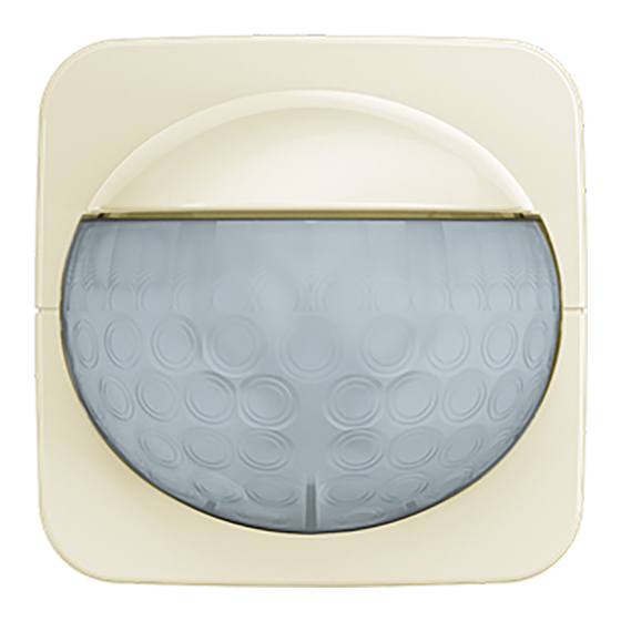
ABB flexTronics Movement detectors Fig. 1: ABB flexTronics Movement detector ABB flexTronics devices have a modular design. The sensor and the actuator are isolated from each other. – The desired function of the mounted movement detector is determined from the combination of the actuator and sensor used. -
Page 12: Device Overview
Overview of product range Device overview In the following you will find an overview of actuators, sensors and control elements for the implementation of lighting control with movement detectors. The brief descriptions of the characteristics provide an initial orientation. For a detailed overview of the characteristics and use cases of the devices: Characteristics (device functions): see chapter 6 “Device Functions“... -
Page 13: Mounting Possibilities
Overview of product range The following sensor variants are available for combining movement detectors: Applications in rooms Basic – Switching of lighting systems in dependence of brightness and/or movement. 64761-xxx-500 Busch-Watchdog 180 flex, Basic sensor with select lens Applications in rooms Comfort –... -
Page 14: Setting Options / Control
Overview of product range Setting options / control Depending on the device, the following methods for setting or configuration are available. When used as an extension unit, only the brightness switching threshold is set. The main units are used to control the switch-off delay. Trimmers on the sensors Fig. - Page 15 Overview of product range Trimmers on the flush-mounted inserts (only in the case of dimmers) Fig. 4: Setting via trimmers: flush-mounted insert of dimmer On the front of the flush-mounted insert, there is a trimmer for setting the operating mode and the minimum brightness.
-
Page 16: Device Functions
Device Functions Device Functions Overview of functions Fig. 5: 180 flex, Basic sensor with select lens: Functions in combination with flush-mounted inserts 64761-xxx-500 180 flex, Basic sensor with select lens Functions in combination with: Purpose Movement detectors — Movement detector —... - Page 17 Device Functions Features Local operation via integrated — — — — — rocker switch Extension operation via additional — push-button possible Brightness-value threshold Minimum brightness — — — — Permanent light — — — — — Memory function — — —...
- Page 18 Device Functions Fig. 6: 180 flex, Comfort sensor with select lens: Functions in combination with flush-mounted inserts 64762-xxx-500 180 flex, Comfort sensor with select lens Functions in combination with: Purpose Movement detectors — Movement detector — — — — Control of channel 2 via extension input Soft ON/OFF —...
- Page 19 Device Functions Brightness-value threshold Minimum brightness — — — — Permanent light — — Memory function — — — — Short-time pulse for e.g. automatic — — — staircase lighting Switch off delay — Switch-off warning — Test mode Only one detection level Product manual 2CKA001473B5204 │19...
- Page 20 Device Functions Fig. 7: 180 flex, Comfort sensor with multi-lens: Functions in combination with flush-mounted inserts 64764-xxx-500 180 flex, Comfort sensor with multi-lens Functions in combination with: Purpose Movement detectors — Movement detector — — — — Control of channel 2 via extension input Soft ON/OFF —...
- Page 21 Device Functions Brightness-value threshold Minimum brightness — — — — Permanent light — — Memory function — — — — Short-time pulse for e.g. automatic — — — staircase lighting Switch off delay — Switch-off warning — Test mode Product manual 2CKA001473B5204 │21...
-
Page 22: Functions
Device Functions Functions Short-time pulse – The output of the device can be configured as electronic current surge sensor to activate a staircase light automaton, for example. Here, during the "On" phase, the output is switched on only periodically for 1 second with 100% brightness and then switched off for 9 seconds. A switch-off delay cannot be set. - Page 23 Device Functions – To increase the detection ranges, additional sensors can be connected in series in conjunction with an extension insert. In this case, the switch-off delay is set and controlled via the sensor of the main unit. – A maximum of 9 extension units may be connected to a main unit via the extension line (PlusWire).
-
Page 24: Detection Range
Device Functions Detection range 64761-xxx-500 180 flex, Basic sensor with select lens 5° -5° Fig. 8: Opening angle of the select lens Fig. 9: Detection ranges: select lens principle Mounting height [D]: 0.8 … 1.2 metres Lengthways toward the detector Crosswise toward the detector A / B 5 metres... - Page 25 Device Functions Fig. 10: Detection range restriction: select lens In the case of the select lens, it is possible to restrict the detection range by masking off the lens. Product manual 2CKA001473B5204 │25...
- Page 26 Device Functions 64762-xxx-500 180 flex, Comfort sensor with select lens 5° -5° Fig. 11: Opening angle of the select lens Fig. 12: Detection ranges: select lens principle Mounting height [D]: 0.8 … 1.2 metres Lengthways toward the detector Crosswise toward the detector A / B 5 metres A / B...
- Page 27 Device Functions Fig. 13: Detection range restriction: select lens In the case of the select lens, it is possible to restrict the detection range by masking off the lens. Product manual 2CKA001473B5204 │27...
- Page 28 Device Functions 64764-xxx-500 180 flex, Comfort sensor with multi-lens 4° 4° -64° -30° -30° -40° -40° -64° Fig. 14: Opening angle of the multi-lens Fig. 15: Detection ranges: multi-lens principle Product manual 2CKA001473B5204 │28...
- Page 29 In the case of the multi-lens, it is possible to restrict the detection range by masking off the lens only to a limited extent. – If this is nevertheless necessary, a masking strip can be requested from the ABB central sales service. Product manual 2CKA001473B5204 │29...
-
Page 30: Switching Capacity
Device Functions Switching capacity Load at 230 V 64814 U-500 3 ... 240 10 ... 240 10 ... 240 16 A 10 ... 240 W 10 ... 240 W e-contact insert flex, 1- W/VA W/VA gang 64811 U-500 16 A 300 W/VA 300 W/VA 2300 W... - Page 31 Device Functions 64814 U-500 10 ... 240 — — e-contact insert flex, 1- gang 2300 VA, 64811 U-500 2300 VA No entry 10 AX at Relay insert flex, 1 gang cos φ 0.9 64821 U-500 1150 VA, No entry Relay insert flex, 2 gang 1150 VA 2x 5 AX at cos φ...
-
Page 32: Technical Data
Technical data Technical data Movement detectors sensors Designation Value Opening angle: 180° Brightness limit value: 1 - 500 lux, daytime operation 10 seconds - 30 minutes ■ Switch-off delay: Short-time pulse 1 second ■ Mounting height: 64761-xxx-500 180 flex, Basic sensor with ■... - Page 33 Technical data Screw-type terminal: Wire cross-section rigid: ■ 64814 U-500 e-contact insert flex, 1-gang ■ 64811 U-500 Relay insert flex, 1 gang 2 × 2.5 mm (maximum) ■ 64891 U-500 Extension unit insert flex 1 × 1.0 mm (minimum) ■ 64851 U-500 LED dimmer insert flex, 1gang ■...
-
Page 34: Connection, Installation / Mounting
Connection, installation / mounting Connection, installation / mounting Requirements for the electrician Danger - Electric voltage! Install the device only if you have the necessary electrical engineering knowledge and experience. Incorrect installation endangers your life and that of the user of the electrical ■... -
Page 35: Mounting / Dismantling
Pull the attachment off only with your hands. – Do not lever parts off with screwdrivers or similar hard objects. All ABB flexTronics inserts are mounted / disassembled the same way. To install the device, perform the following steps: 7 mm 1. - Page 36 Connection, installation / mounting 2. Plug the sensor / control element together with the cover frame onto the flush-mounted device insert. – Cover frames are not included in the scope of delivery and must be purchased separately. The flex device combination is mounted. Product manual 2CKA001473B5204 │36...
-
Page 37: Electrical Connection
Connection, installation / mounting Electrical connection Example for connection Fig. 16: Connection example: main unit with extension unit and extension unit push-button [1] Master thermostat – "Relay insert flex, 1 gang" with "Busch-Watchdog 180 flex, Comfort sensor with select lens" [2] Option: Extension unit push-button –... -
Page 38: Commissioning
Commissioning Commissioning Commissioning does not take place. The sensors are ready for operation directly after they are attached to the flex insert. – For subsequent further parameter setting: see chapter 10.4 “Special functions of the comfort sensors“ on page 44. Product manual 2CKA001473B5204 │38... -
Page 39: Operation
Operation Operation 10.1 Operation of sensors Fig. 18: Control elements [1] Trimmers [2] Trimmers [3] Test LED [4] Rocker button top [5] Rocker button bottom Notice The function of the setting elements depends on the flex insert used. Local operation via rocker button [4] / [5] The attached sensor is designed as a rocker. - Page 40 Operation Rocker button bottom [5]: – Brief press of the button: – Switch light off immediately. – The switch-on can only take place after the movement-dependent blockage time. – Long press of the button: – Mounting on relay insert or e-contact insert: –...
-
Page 41: Device Settings Of Settings
Operation 10.2 Device settings of settings Fig. 19: Control elements [1] Trimmers [2] Trimmers [3] Test LED [4] Rocker button top [5] Rocker button bottom Notice The function of the setting elements depends on the flex insert used. Brightness switching threshold The brightness-value threshold and operation independent of the brightness are set via the trimmer [1] on the rear of the device. - Page 42 Operation Position between both symbols: – Determine a setting by testing until the desired response threshold is reached. – Walk back and forth in front of the sensor until the flush-mounted sensor triggers. Stop and remain still until the consumers are switched off. Confirm the test results by walking again if pertinent.
-
Page 43: Extension Operation (Option)
Operation – Deactivate the activation test again after the test is completed. This is done by resetting the trimmer [1] to the desired brightness-value threshold. 10.3 Extension operation (Option) Extension operation via push-button The light can be switched at any time via an extension unit push-button. The switch-off takes place only after the detection range has been exited and the set switch- ■... -
Page 44: Special Functions Of The Comfort Sensors
Operation 10.4 Special functions of the comfort sensors Fig. 20: Control elements for special functions [1] LED [2] Rocker button top [3] Rocker button bottom Parameter setting / Setup The following parameters can be set via the setup procedure specific to the device. Switch-off prewarning ■... - Page 45 Operation Memory function (only in combination with a flex dimmer insert): 1. Calling up setup: – Press the top rocker button [2] for >10 seconds. – The status LED [1] flashes slowly. 2. Activate / deactivate the memory function (this is only possible in the unit combination with the dimmer insert): –...
-
Page 46: Device Settings Of The Dimmer
Operation 10.5 Device settings of the dimmer 10.5.1 Introduction The minimum brightness determines the luminosity down to which dimming is possible. The minimum brightness of the flush-mounted insert of the dimmer can be set with the operating part removed by adjusting the trimmer on the front of the device. Depending on the type of load connected, the appropriate operating mode is also selected during the setting. -
Page 47: Minimum Brightness
Operation 10.5.3 Minimum brightness Fig. 21: Setting the minimum brightness Depending on the set operating mode, the minimum brightness is set in the right [1] or left [2] setting range of the trimmer. – To set the operating mode: see chapter 10.5.2 “Operating modes“ on page 46. The setting of the minimum brightness is signalled directly by the connected lighting. -
Page 48: Maintenance
Maintenance Maintenance 11.1 Cleaning Caution! - Risk of damaging the device! When spraying on cleaning agents, these can enter the device through ■ crevices. – Do not spray cleaning agents directly onto the device. Aggressive cleaning agents can damage the surface of the device. ■... -
Page 49: Information About Planning And Application
Information about planning and application Information about planning and application 12.1 Principles of function / principles of operation 12.1.1 The difference between movement detectors / presence detectors Both device types are passive infrared detectors. The serve for switching the lighting when people are present. -
Page 50: Principles Of Function
Information about planning and application 12.1.2 Principles of function Infrared radiation, also called heat radiation, consists of electromagnetic waves. Every object transmits a characteristic heat radiation, depending on its specific temperature. The detection of movement depends on the mounting height and the "free view" of the device. Infrared sensor technology (IR sensor technology) 100A 0,4µm 0,7µm 0,1cm... - Page 51 Light measurement Fig. 25: Brightness sensor The devices of ABB are fitted with an ambient light measurement. This extends the movement detection process by one brightness-value threshold. The brightness-value threshold determines the luminosity from which the light switches on. If the surrounding light is brighter that the set brightness-value threshold, the light does not switch on if movement is detected.
-
Page 52: Lens Types
Lens types Fig. 26: Lens types The devices of ABB are fitted with Fresnel lenses. Compared to normal lenses, Fresnel lenses offer the advantage of an increase in the amplification of infrared radiation. [1] Normal lens (hemispherical) [2] Fresnel lens 12.1.4... - Page 53 Information about planning and application Moving lengthways to/in parallel with the device Fig. 28: Moving lengthways to/in parallel with the device The detection width is physically dependent smaller when the person to be detected moves directly toward the device [A] or in parallel [B] (e.g., in a corridor) with it. In the bottom example graphic a new sector is touched by the person only at the end of a 1 m path (arrow).
- Page 54 Information about planning and application Mounting heights Fig. 29: Mounting heights Depending on the mounting height, the detection characteristics change. As the mounting height increases, the sensitivity and detection density decrease. In the left side of the example graphic, the movement is no longer detected because it does not cut across any additional sectors.
-
Page 55: Case Studies
Information about planning and application 12.2 Case studies 12.2.1 Corridor Function Fig. 30: Application example: corridor with light and dark areas A corridor lighting system should be controlled intelligently via a Busch-Watchdog. In this corridor there are light and dark areas due to an unfavourable distribution of daylight. The lighting should be switched depending on movement and the prevailing lighting conditions. - Page 56 Information about planning and application Setting the brightness-value thresholds Fig. 31: Application example: corridor with light and dark areas – setting the brightness-value threshold In this example, the brightness threshold of the sensors of the main unit and the extension unit are set to the same level.
- Page 57 Information about planning and application Connection Fig. 32: Application example: corridor with light and dark areas – connection [1] Master thermostat – "Relay insert flex, 1 gang" with "Busch-Watchdog 180 flex, Comfort sensor with select lens" [2] Option: Extension unit push-button –...
-
Page 58: Stairwell
Information about planning and application 12.2.2 Stairwell Function In a stairwell, the lighting is to be switched via movement detectors. Fig. 33: Application example: stairwell with multi-lens sensor A multi-lens sensor is particularly suitable for this situation. If there are several floors, a multi-lens sensor is installed on one floor as the main unit. The other floors are extended accordingly with multi-lens sensors as extension units. - Page 59 Information about planning and application Connection Fig. 34: Application example: stairwell – connection [1] Master thermostat – "Relay insert flex, 1 gang" with "Busch-Watchdog 180 flex, Comfort sensor with multi- lens" [2] Option: Extension unit push-button – E.g.: 2020 US/500 –...
-
Page 60: Sources Of Interference
Information about planning and application 12.3 Sources of interference Moving heating air Fig. 35: Movement detector malfunction source: moving heating air Movement detectors react to infrared radiation (heat radiation). If the movement detector is located in an area where warm air moves strongly, this can lead to undesired switching operations of the movement detector. -
Page 61: Notes
Notes Notes Product manual 2CKA001473B5204 │61... -
Page 62: Index
Index Index ABB flexTronics ..........11 Maintenance ..........48 Applications ..........10 Minimum brightness ........47 Mounting ............. 35 Mounting possibilities ........13 Basic principles ..........9 Movement detectors ........49 Case studies ..........12, 55 Notes ............61 Cleaning ............. 48 Notes on the instruction manual ...... - Page 63 Busch-Jaeger Elektro GmbH A member of the ABB Group Freisenbergstraße 2 58513 Lüdenscheid www.BUSCH-JAEGER.com info.bje@de.abb.com Central sales service: Tel.: +49 2351 956-1600 Fax: +49 2351 956-1700 Copyright © 2021 Busch-Jaeger Elektro GmbH All rights reserved...