Sony HT-CT800 Service Manual
Sound bar
Hide thumbs
Also See for HT-CT800:
- Operating instructions manual (355 pages) ,
- Startup manual (2 pages) ,
- Startup manual (2 pages)
Table of Contents
Advertisement
2019/09/24 22:06:08 (GMT+09:00)
SERVICE MANUAL
Ver. 1.3 2017.10
• All of the units included in
the HT-CT800 (SA-CT800/
SA-WCT800/Remote con-
trol) are required to confi rm-
ing operation of SA-CT800.
Check in advance that you
have all of the units.
Note:
Be sure to keep your PC used for service and
checking of this unit always updated with the
latest version of your anti-virus software.
In case a virus affected unit was found during
service, contact your Service Headquarters.
COMPONENT MODEL NAME
Bar Speaker (Active Speaker System)
Subwoofer (Active Subwoofer)
• Please refer to service manual separately issued for Subwoofer.
Amplifier section
(US)
POWER OUTPUT AND TOTAL HARMONIC
DISTORTION:
(FTC)
Front L + Front R:
With 4 ohms loads, both channels
driven, from 200 - 20,000 Hz; rated
35 W per channel minimum RMS
power, with no more than 1% total
harmonic distortion from 250 mW to
rated output.
(Except US)
POWER OUTPUT (rated)
Front L + Front R: 60 W + 60 W
(at 4 ohms, 1 kHz, 1% THD) (Except LA, CH)
(per channel at 4 ohms, 1 kHz, 1% THD) (LA)
(at 4 ohms, 1 kHz) (CH)
POWER OUTPUT (reference) (Except CH)
Front L/Front R speaker blocks: 110 W
(per channel at 4 ohms, 1 kHz)
Inputs
HDMI IN 1/2/3*
ANALOG IN
TV IN (OPTICAL)
Outputs
HDMI OUT (TV (ARC))*
* HDMI IN 1/2/3 and HDMI OUT (TV (ARC))
jacks support HDCP 2.2 protocol. HDCP
2.2 is newly enhanced copyright
protection technology that is used to
protect content such as 4K movies.
HDMI Section
Connector
Type A (19pin)
USB section
(USB) port:
Type A (For connecting USB memory)
LAN section
LAN(100) terminal
100BASE-TX Terminal
Wireless LAN section
Communication system
IEEE 802.11 a/b/g/n
Frequency band (Except CH)
2.4 GHz, 5 GHz
Frequency band (CH)
2.4 GHz - 2.4835 GHz
5.15 GHz - 5.35 GHz
5.725 GHz - 5.85 GHz
9-896-351-04
2017J33-1
©
2017.10
HT-CT800
SA-CT800
SA-WCT800
(CH)
BLUETOOTH section
Communication system
BLUETOOTH Specification version 4.1
Output
BLUETOOTH Specification Power
Class 1
Maximum communication range
Line of sight approx. 30 m
Maximum number of devices to be
registered
9 devices
Frequency band
2.4 GHz band (2.4 GHz - 2.4835 GHz)
Modulation method
FHSS (Freq Hopping Spread Spectrum)
Compatible BLUETOOTH profiles
A2DP 1.2 (Advanced Audio Distribution
Profile)
AVRCP 1.5 (Audio Video Remote
Control Profile)
Supported Codecs
4)
SBC
, AAC
Transmission range (A2DP)
20 Hz - 40,000 Hz (LDAC sampling
frequency 96 kHz with 990 kbps
transmission)
20 Hz - 20,000 Hz (Sampling frequency
44.1 kHz)
(CH)
1)
The actual range will vary depending on
factors such as obstacles between
devices, magnetic fields around a
microwave oven, static electricity,
cordless phone use, reception
sensitivity, the operating system,
software applications, etc.
2)
BLUETOOTH standard profiles indicate
the purpose of BLUETOOTH
communication between devices.
Sony Video & Sound Products Inc.
Photo: SA-CT800
SPECIFICATIONS
3)
Codec: Audio signal compression and
conversion format
4)
Abbreviation for Subband Codec
5)
Abbreviation for Advanced Audio
Coding
Front L/Front R speaker block section
Speaker system
Full range speaker system, Acoustic
suspension
Speaker
60 mm (2 3/8 in) cone type
General
Power requirements
120 V AC, 60 Hz (US, CND)
120 V AC, 50 Hz/60 Hz (TW)
120 V - 240 V AC, 50 Hz/60 Hz (EA3, LA)
220 V - 240 V AC, 50 Hz/60 Hz
1)
(AEP, UK, E3, SP1, AR, TH, AUS, CH)
Power consumption
On: 42 W
Dimensions* (approx.) (w/h/d)
1,030 mm × 52 mm × 126 mm
(40 5/8 in x 2 1/8 in x 5 in)
(without wall mounting brackets)
1,030 mm × 120 mm × 68.5 mm
2)
(40 5/8 in x 4 3/4 in x 2 3/4 in)
(with wall mounting brackets)
1,030 mm × 62 mm × 126 mm
(40 5/8 in x 2 1/2 in x 5 in)
(with feet)
3)
*Not including projection portion
5)
, LDAC
Mass (approx.)
2.8 kg (6 lb 2 3/4 oz)
Compatible iPod/iPhone models
The compatible iPod/iPhone models are as
follows. Update your iPod/iPhone with the
latest software before using with the
system.
BLUETOOTH technology works with:
iPhone 7 Plus/iPhone 7/iPhone SE/iPhone
6s Plus/iPhone 6s/iPhone 6 Plus/
iPhone 6/iPhone 5s/iPhone 5c/iPhone 5/
iPhone 4s
iPod touch (6th generation)/iPod touch
(5th generation)
HT-CT800
Canadian Model
AEP Model
Australian Model
Chinese Model
Wireless transmitter section
Communication system
Wireless Sound Specification version
2.0
Frequency band
2.4 GHz (2.4000 GHz - 2.4835 GHz)
Modulation method
Pi/4 DQPSK
(CH)
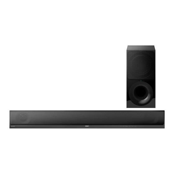
What's in the Box
Design and specifications are subject to
change without notice.
SOUND BAR
ACTIVE SPEAKER SYSTEM
SA-CT800
US Model
UK Model
E Model
HT-CT800
SA-CT800
SYS SET
Advertisement
Table of Contents

Related Manuals for Sony HT-CT800


Summary of Contents for Sony HT-CT800
- Page 1 5.15 GHz - 5.35 GHz sensitivity, the operating system, 5.725 GHz - 5.85 GHz software applications, etc. BLUETOOTH standard profiles indicate the purpose of BLUETOOTH communication between devices. 9-896-351-04 2017J33-1 Sony Video & Sound Products Inc. © 2017.10 SYS SET...
- Page 2 Leakage current can be measured by any one of three methods. registered trademarks owned by Bluetooth compatible coding technologies such as SIG, Inc. and any use of such marks by Sony 1. A commercial leakage tester, such as the Simpson 229 or RCA SBC, it operates without any down- Corporation is under license.
-
Page 3: Table Of Contents
2019/09/24 22:06:08 (GMT+09:00) HT-CT800 TABLE OF CONTENTS SERVICING NOTES TEST MODE ......................31 DISASSEMBLY TROUBLESHOOTING .......... 40 2-1. Disassembly Flow ............2-2. Top Cabinet Block ............10 DIAGRAMS 2-3. TOUCH Board ..............11 5-1. Block Diagram - HDMI Section - ........44 2-4. - Page 4 ADVANCE PREPARATION WHEN CONFIRMING OP- ERATION Destination Part No. Destination code All of the units included in the HT-CT800 (SA-CT800/SA-WCT800/ US, CND models 4-684-824-0[] Remote control) are required to confi rming operation of SA- AEP model 4-684-826-0[] CT800.
- Page 5 2019/09/24 22:06:08 (GMT+09:00) HT-CT800 NOTE OF REPLACING THE MB-1612 BOARD OR Diag WLAN/BT COMBO CARD Category: Wireless LAN Test When the MB-1612 board or WLAN/BT combo card is replaced, be sure to perform with referring to the following item. Diag When replacing the MB-1612 board:...
- Page 6 2019/09/24 22:06:08 (GMT+09:00) HT-CT800 NETWORK AND NFC CONNECTION CHECKING METH- 9. Press the [V]/[v] buttons on the remote commander to select the “Auto”, and press the [b] button on the remote command- When the MB-1612 board or WLAN/BT combo card is replaced, 10.
- Page 7 2019/09/24 22:06:08 (GMT+09:00) HT-CT800 INITIALIZING METHOD WIRELESS CONNECTION (LINK) WORK OF BAR SPEAK- It can return all settings to the initial state of factory shipment. ER AND SUBWOOFER Note 1: Disconnect the following connections when using this mode. When the parts below is replaced, the wireless connection (LINK) ...
- Page 8 2019/09/24 22:06:08 (GMT+09:00) HT-CT800 BOND FIXED POSITION OF ELECTRICAL PARTS When the parts that fi xed on the board by the bond have been removed, fi x the parts by using the bond (ADHESIVE (SC608Z2)) in the mounting to the board. (Refer to the fi gure below) ]: Bond application portion –...
-
Page 9: Disassembly
2019/09/24 22:06:08 (GMT+09:00) HT-CT800 SECTION 2 DISASSEMBLY • This set can be disassembled in the order shown below. 2-1. DISASSEMBLY FLOW 2-27. SERVICE POSITION (SIDE A) 2-28. SERVICE POSITION (SIDE B) (Page 30) (Page 30) 2-10. USB-CHUKEI BOARD BLOCK 2-2. TOP CABINET BLOCK... -
Page 10: Top Cabinet Block
2019/09/24 22:06:08 (GMT+09:00) HT-CT800 Note: Follow the disassembly procedure in the numerical order given. 2-2. TOP CABINET BLOCK 1 twelve screws (BVTP3 bottom side Note 1: Lay a soft piece of cloth under the unit to avoid damaging the top cabinet assy. -
Page 11: Touch Board
2019/09/24 22:06:08 (GMT+09:00) HT-CT800 2-3. TOUCH BOARD filament tape FFC 6P 1 filament tape (sub material) (sub material) front side 3 FFC 6P (CN1901) TOUCH 5 TOUCH board terminal board side right side 4 W-adhesive tape top cabinet block rear side W-adhesive tape... -
Page 12: Sircs Board
2019/09/24 22:06:08 (GMT+09:00) HT-CT800 2-5. SIRCS BOARD 4 SIRCS board Note: When installing the SIRCS board, – – align the groove and rib. top side groove Bend the wire. 1 DISPLAY board cable connector right side (CN891) DISPLAY board block bottom side... -
Page 13: Organic El Indicator Element (Oled1)
2019/09/24 22:06:08 (GMT+09:00) HT-CT800 2-7. ORGANIC EL INDICATOR ELEMENT (OLED1) 1 cushion (OLED) left side 3 organic EL indicator element (OLED1) top side DISPLAY bracket block 2 Peel the organic EL indicator element off of the adhesive sheet. right side SYS SET... -
Page 14: Loudspeaker (R-Ch) (Sp2)
2019/09/24 22:06:08 (GMT+09:00) HT-CT800 2-8. LOUDSPEAKER (R-CH) (SP2) Note 3: When connecting the terminals of the connection cable to the loudspeaker, be careful of the direction of the terminals. 4 connection cable block (R-ch) packing (CL3) 3 terminal (narrow) [black] loudspeaker (R-ch) -
Page 15: Loudspeaker (L-Ch) (Sp1)
2019/09/24 22:06:08 (GMT+09:00) HT-CT800 2-9. LOUDSPEAKER (L-CH) (SP1) 3 terminal (narrow) [black] 3 terminal (wide) [gray] 1 tape packing 5 two screws (CL3) (BVTP3.5) 1 two tapes 5 screw (BVTP3.5) loudspeaker (L-ch) (SP1) 6 loudspeaker wide (L-ch) (SP1) left side 4 connection... -
Page 16: Usb-Chukei Board Block
2019/09/24 22:06:08 (GMT+09:00) HT-CT800 2-10. USB-CHUKEI BOARD BLOCK 8 connector 7 connector (CN5004) (CN501) 4 screw CN501 CN5004 (BVTP3 rear side 4 screw 9 cushion (BVTP3 5 wire (CL3) groove qa USB-CHUKEI board block Note: When installing the USB-CHUKEI board block, align the rib and groove. -
Page 17: Usb-Chukei Board
2019/09/24 22:06:08 (GMT+09:00) HT-CT800 2-11. USB-CHUKEI BOARD 10 mm 1 mm to USB-CHUKEI board to MB-1612 board 5 MB-1612 board connection cable (6P) Note 1: Arrange the cable along the white line on the USB-CHUKEI board. Note 2: When affixing the cushion (CZ2-A), be careful that it does not obstruct the screw hole. -
Page 18: Btw (Wifi) Board Block
2019/09/24 22:06:08 (GMT+09:00) HT-CT800 Ver. 1.3 2-13. BTW (WIFI) BOARD BLOCK Note: This part is deleted from the midway of production. 3 three screws guide line cushion (WIFI label) (BVTP3 guide line 4 BTW (WIFI) board block front side Pressing the adhesive area. -
Page 19: Btw (Wifi) Board
2019/09/24 22:06:08 (GMT+09:00) HT-CT800 2-14. BTW (WIFI) BOARD front side Triangle shape. marking Triangle shape. Triangle shape. marking BTW (WIFI-1) board BTW (WIFI-2) board marking Upward arrow. Upward arrow. left side right side rear side coaxial harness coaxial harness [gray] [white] top side... -
Page 20: Btw (Bt) Board Block
2019/09/24 22:06:08 (GMT+09:00) HT-CT800 Ver. 1.3 2-15. BTW (BT) BOARD BLOCK Note: This part is deleted from the midway of production. 1 cushion (WIFI label) guide line cushion (WIFI label) guide line 2 connector (No. 1) [black] front side Pressing the adhesive area. -
Page 21: Btw (Bt) Board
2019/09/24 22:06:08 (GMT+09:00) HT-CT800 2-16. BTW (BT) BOARD top side right side Triangle shape. Triangle shape. front side Upward arrow. 4 BTW (BT) board marking 1 antenna holder front side 2 connector right side coaxial left side [black] rear side harness marking... -
Page 22: Wlan/Bt Combo Card (Wifi1)
2019/09/24 22:06:08 (GMT+09:00) HT-CT800 Ver. 1.3 2-17. WLAN/BT COMBO CARD (WIFI1) Note 1: When the WLAN/BT combo card (Ref. No. WIFI1) is re- Note 2: If the radiation sheet is damaged, be sure to replace them with placed, refer to “NOTE OF REPLACING THE MB-1612 new parts. -
Page 23: Insulation Top Assy
2019/09/24 22:06:08 (GMT+09:00) HT-CT800 2-18. INSULATION TOP ASSY slot 1 four screws (BVTP3 1 five screws (BVTP3 front side power cord left side slot 2 insulation top assy front side front side WLAN/BT combo card cable bottom cabinet block 2-19. POWER CORD (AC1) Note: When installing the power cord block, check the direction and position of claw of the cord bushing (FBS001) and install correctly. -
Page 24: Power Board
2019/09/24 22:06:08 (GMT+09:00) HT-CT800 2-20. POWER BOARD 7 POWER board Note 2: When installing the POWER board, align the two ribs and two holes. Note 3: The wire must not touch the screw boss and four capacitors hole 3 screw 3 three screws (C976, C977, C6050, C6068). -
Page 25: Rf Modulator (Rf1)
2019/09/24 22:06:08 (GMT+09:00) HT-CT800 Ver. 1.3 2-22. RF MODULATOR (RF1) Note 1: When the RF modulator (RF1) is replaced, refer to “WIRE- LESS CONNECTION (LINK) WORK OF BAR SPEAKER AND SUBWOOFER” on page 7. 2 packing (CL3) bottom side RF modulator block... -
Page 26: Shield (Main) Block-1
2019/09/24 22:06:08 (GMT+09:00) HT-CT800 2-23. SHIELD (MAIN) BLOCK-1 • Continued on 2-24 (page 27). 3 USB-CHUKEI board cable connector (CN5004) 2 USB-CHUKEI board cable top side CN501 CN5004 connector (CN501) rear side 4 WLAN/BT combo card cable connector (CN502) CN502 1 Remove the two USB-CHUKEI board cables from the wiring stopper. -
Page 27: Shield (Main) Block-2
2019/09/24 22:06:08 (GMT+09:00) HT-CT800 2-24. SHIELD (MAIN) BLOCK-2 1 screw 1 screw (BVTP3 1 four screws (BVTP3 (BVTP3 2 ground plate 1 two screws (BVTP3 1 screw top side (BVTP3 3 shield (main) block 1 screw (BVTP3 bottom cabinet block front side rear side SYS SET... -
Page 28: Mb-1612 Board
2019/09/24 22:06:08 (GMT+09:00) HT-CT800 2-25. MB-1612 BOARD Note 1: When the MB-1612 BOARD is replaced, refer to “NOTE Note 2: If the radiation sheet is damaged, be sure to replace them with OF REPLACING THE MB-1612 BOARD OR WLAN/BT new parts. COMBO CARD” on page 5, “BOND FIXED POSITION OF ELECTRICAL PARTS”... -
Page 29: Bottom Chassis Block
2019/09/24 22:06:08 (GMT+09:00) HT-CT800 Ver. 1.3 2-26. BOTTOM CHASSIS BLOCK Note: This part is deleted from the midway of production. 1 cushion (WIFI label) guide line cushion (WIFI label) 8 bottom chassis block guide line 6 two screws front side (BVTP3 Pressing the adhesive area. -
Page 30: Service Position (Side A)
2019/09/24 22:06:08 (GMT+09:00) HT-CT800 2-27. SERVICE POSITION (SIDE A) POWER board MB-1612 board RF modulator block insulating sheet 2-28. SERVICE POSITION (SIDE B) insulating sheet POWER board MB-1612 board SYS SET... -
Page 31: Test Mode
2019/09/24 22:06:08 (GMT+09:00) HT-CT800 Ver. 1.3 SECTION 3 TEST MODE ALL RESET 6. In the state of step 3, touch the [VOL +] button and “CG3_A” (model name) is displayed on the front panel display. (“A” will It can initialize all settings of IFCon and SYSCON. - Page 32 2019/09/24 22:06:08 (GMT+09:00) HT-CT800 TOUCH-SENSOR DEBUG AMP TEST It can inspect the sensitivity of the touch key. It can perform the AMP setting and measurement. If the operation in the touch key at the “PANEL TEST” (on page 31) was insecure, check the sensitivity of the touch key in this Procedure: mode.
- Page 33 2019/09/24 22:06:08 (GMT+09:00) HT-CT800 6. Each time the [CLEAR AUDIO+] button on the remote com- WIRELESS SOUND COLD RESET mander is pressed, VACS on/off setting is changed. It can initialize various backup information of Subwoofer (SA- WCT800). VAOFF Preparation: Connect the Subwoofer (SA-WCT800) and the Bar Speaker (SA- CT800) by wireless.
- Page 34 2019/09/24 22:06:08 (GMT+09:00) HT-CT800 SERVICE MODE Note: The operation in this mode must a TV monitor and supplied remote commander. Setting method of the service mode: 1. Connect this unit with TV monitor. 2. Touch the [ ] button to turn the power on.
- Page 35 2019/09/24 22:06:08 (GMT+09:00) HT-CT800 2. Menu Tree Service Mode Menu Device Test Diag Service Mode Menu [1] Diag [1] Diag [2] Log [2] Log [3] Factory Initialize [3] Factory Initialize [4] Network [4] Network Video Test [5] Version Up [5] Version Up...
- Page 36 2019/09/24 22:06:08 (GMT+09:00) HT-CT800 3. Service Mode Menu (Top Menu) 4. Diag (Device Test) This is the top menu of service mode. This screen is used for test of each devices mounted on the board. Each function is accessed from this screen.
- Page 37 2019/09/24 22:06:08 (GMT+09:00) HT-CT800 7. Diag (Wireless LAN Test) Diag This screen performs wireless LAN/Miracast test. Category: Wireless LAN Test Screen 1: Selects the wireless LAN test category Operation: Diag [B]/[b] Selects the category Category: Wireless LAN Test [v]/[ ] Moves to the selected category...
- Page 38 2019/09/24 22:06:08 (GMT+09:00) HT-CT800 11. Diag (Bluetooth Device Test) Diag This screen performs Bluetooth device test. Category: Bluetooth Device Test Screen 1: Selects the Bluetooth device test category Operation: Diag [B]/[b] Selects the category Category: Bluetooth Device Test [v]/[ ] Moves to the selected category...
- Page 39 2019/09/24 22:06:08 (GMT+09:00) HT-CT800 12. Log: Error Log (Output of each Log) 16. Version UP Note: Not used for the servicing. This screen displays the contents of each log. Note 1: Do not refer to the displayed date. 17. System Information (System Information Display) This screen displays system information.
-
Page 40: Troubleshooting
2019/09/24 22:06:08 (GMT+09:00) HT-CT800 SECTION 4 TROUBLESHOOTING 1. “PRTCT”, “PUSH” and “POWER” is displayed on the front panel display after turning the power on “PRTCT”, “PUSH” and “POWER” is alternately displayed on the front panel display after turning the power on. IC6005 on the MB-1612 board is Replace the IC6005 on the MB-1612 board. - Page 41 2019/09/24 22:06:08 (GMT+09:00) HT-CT800 2. The video and audio of HDMI is not outputted The video and audio of HDMI is not outputted. The voltage of the following is about 3.3 V. The voltage of the following is 5.0 V. MB-1612 board: IC301 pin 5...
- Page 42 2019/09/24 22:06:08 (GMT+09:00) HT-CT800 – From page 41 – Check the mounted state of connector (CN3004), diode The voltage of the following is about 3.3 V. The voltage of the following is about 3.3 V. (D5001), IC5001 and resistor MB-1612 board: CN3004 pin 13 (CEC)
- Page 43 2019/09/24 22:06:08 (GMT+09:00) HT-CT800 3. The sound is not outputted The sound is not outputted. Entering the “DEMO MODE” (touch Check the signal path for being inputted to the [INPUT] button for five seconds), the IC101 on the MB-1612 board, and and then the “DEMO MODE” sound then replace the complete MB-1612 board.
-
Page 44: Diagrams
2019/09/24 22:06:08 (GMT+09:00) HT-CT800 SECTION 5 DIAGRAMS 5-1. BLOCK DIAGRAM - HDMI Section - DATA0+ 74 P3RX0P HDMI REPEATER CLOCK 27M_CLK >001B DATA0– 73 P3RX0M IC3000 SYSCLK/XI 170 BUFFER IC3011 (Page 45) DATA1+ 77 P3RX1P DATA1– 76 P3RX1M CN3004 DATA2+ 80 P3RX2P HDMI OUT DATA2–... -
Page 45: Block Diagram - Main Section
2019/09/24 22:06:08 (GMT+09:00) HT-CT800 5-2. BLOCK DIAGRAM - MAIN Section - SD-RAM IC102 DQL0 – DQL7, RDQ0 – RDQ15 DQU0 – DQU7 IC101 (2/3) A0 – A13, NC RA0 – RA14 AMP_D1 (L/R), AMP_D3, AMP_BCK, AG17 RCLK0 AMP_LRCK, AMP_MCK ARC_SPDIF AMP_D1 (L/R) >003B... -
Page 46: Block Diagram - Amp Section
2019/09/24 22:06:08 (GMT+09:00) HT-CT800 5-3. BLOCK DIAGRAM - AMP Section - STREAM PROCESSOR DIGITAL POWER AMP IC6004 IC6005 AMP_D1 (L/R), AMP_D3, AMP_BCK, L6006 AMP_LRCK, AMP_MCK AMP_D1 (L/R) >004B SDIN1 PWM_P_4 49 INPUT_A OUT_A 39 AMP_D3 SDIN3 (L-CH) (Page 45) AMP_BCK SCLK OUT_A 40... -
Page 47: Block Diagram - Panel/Power Supply Section
2019/09/24 22:06:08 (GMT+09:00) HT-CT800 5-4. BLOCK DIAGRAM - PANEL/POWER SUPPLY Section - DC/DC CONVERTER IC304 +3.3V SYSTEM CONTROLLER +3.3V REGULATOR 1.2V 14 SW2 VIN2 IC5001 (4/4) (FOR IC1901) NFC BOARD IC1902 DDR_1.5V 3 SW1 VIN1 39 NFC_DATA TS_PCONT VREF_0.75V 40 NFC_CLK B+ SWITCH 35 NFC_IRQ 3.3V... - Page 48 2019/09/24 22:06:08 (GMT+09:00) HT-CT800 Ver. 1.1 THIS NOTE IS COMMON FOR PRINTED WIRING BOARDS AND SCHEMATIC DIAGRAMS. • Circuit Boards Location (In addition to this, the necessary note is printed in each block.) BTW (WIFI-2) board For Printed Wiring Boards. For Schematic Diagrams.
-
Page 49: Printed Wiring Board - Mb-1612 Board
2019/09/24 22:06:08 (GMT+09:00) HT-CT800 Ver. 1.1 5-5. PRINTED WIRING BOARD - MB-1612 Board - • See page 48 for Circuit Boards Location. • : Uses unleaded solder. WIFI1 (Page 50) (Page 51) (Page 50) USB-CHUKEI BOARD USB-CHUKEI BOARD >03P >02P >04P WLAN/BT... -
Page 50: Printed Wiring Board - Usb-Chukei Board
2019/09/24 22:06:08 (GMT+09:00) HT-CT800 5-6. PRINTED WIRING BOARD - USB-CHUKEI Board - 5-7. SCHEMATIC DIAGRAM - USB-CHUKEI Board - • See page 48 for Circuit Boards Location. • : Uses unleaded solder. USB-CHUKEI BOARD USB-CHUKEI BOARD (COMPONENT SIDE) C1401 MB-1612 BOARD >03P... -
Page 51: Printed Wiring Boards - Antenna Section
2019/09/24 22:06:08 (GMT+09:00) HT-CT800 5-8. PRINTED WIRING BOARDS - ANTENNA Section - 5-9. SCHEMATIC DIAGRAM - ANTTENA Section - • See page 48 for Circuit Boards Location. • : Uses unleaded solder. BTW (BT) BOARD BTW (BT) BOARD (SIDE A) ANT1 J2401... -
Page 52: Printed Wiring Boards - Display/Sircs Boards
2019/09/24 22:06:08 (GMT+09:00) HT-CT800 5-10. PRINTED WIRING BOARDS - DISPLAY/SIRCS Boards - • See page 48 for Circuit Boards Location. • : Uses unleaded solder. OLED1 ORGANIC EL DISPLAY BOARD (SIDE A) INDICATOR ELEMENT FFC4 FB1302 R1313 CN1301 JL1307 C1307 FB1301 C1309... -
Page 53: Schematic Diagram - Display/Sircs Boards
2019/09/24 22:06:08 (GMT+09:00) HT-CT800 5-11. SCHEMATIC DIAGRAM - DISPLAY/SIRCS Boards - DISPLAY BOARD JL1301 CN1301 C1313 D1301 CL-194S-HB8SP-SD-T E3.3V BLUETOOTH FFC4 INDICATOR >01S R1303 Q1301 LTC023JUBFS8TL TOUCH LED DRIVE PCONT_TS BOARD CN1303 CN1901 DGND R1310 R1311 C1311 (Page 56) CL1317 FB1304 LED_5V... -
Page 54: Printed Wiring Board - Power Board
2019/09/24 22:06:08 (GMT+09:00) HT-CT800 Ver. 1.3 5-12. PRINTED WIRING BOARD - POWER Board - • See page 48 for Circuit Boards Location. • : Uses unleaded solder. POWER BOARD JL939 JL904 ET931 C902 (Except US, CND, TW) R914 (CHASSIS) C989 (US, CND, TW) -
Page 55: Schematic Diagram - Power Board
2019/09/24 22:06:08 (GMT+09:00) HT-CT800 Ver. 1.3 5-13. SCHEMATIC DIAGRAM - POWER Board - • See page 57 for IC Block Diagrams. POWER BOARD JL904 ET931 JL939 (CHASSIS) CN901 F901 C989 C990 C902 C903 JL902 LF901 0.001 0.001 0.0022 0.0022 250V 250V 250V... -
Page 56: Printed Wiring Board - Touch Board
2019/09/24 22:06:08 (GMT+09:00) HT-CT800 5-14. PRINTED WIRING BOARD - TOUCH Board - • See page 48 for Circuit Boards Location. • : Uses unleaded solder. TOUCH BOARD (SIDE A) C1907 IC1902 C1901 JL1901 R1910 FFC4 C1906 JL1905 R1911 IC1901 >01P R1901 FB001... - Page 57 2019/09/24 22:06:08 (GMT+09:00) HT-CT800 Ver. 1.1 • IC Block Diagrams – POWER Board – – TOUCH Board – IC930 STR-Y6735 (US, CND, TW) IC1902 MM3411A33URE IC930 STR-Y6766B (Except US, CND, TW) CE 1 BIAS D/ST 1 STARTUP VOLTAGE – DRIVER REFERENCE OVERCURRENT...
- Page 58 2019/09/24 22:06:08 (GMT+09:00) HT-CT800 • IC Pin Function Description TOUCH BOARD IC1901 CY8CMBR3108-LQXIT (TOUCH KEY CONTROLLER) Pin No. Pin Name Description 1, 2 CS0/PS0, CS1/PS1 Fixed at “L” in this unit CMOD External capacitor connection terminal Internal regulator output terminal VDDIO Power supply terminal (+3.3V) Power supply terminal (+3.3V)
-
Page 59: Exploded Views
2019/09/24 22:06:08 (GMT+09:00) HT-CT800 Ver. 1.1 SECTION 6 EXPLODED VIEWS Note: • -XX and -X mean standardized parts, so The components identifi ed by mark 0 The components identifi ed by mark 9 con- they may have some difference from the or dotted line with mark 0 are critical for tain confi... -
Page 60: Top Cabinet Section
2019/09/24 22:06:08 (GMT+09:00) HT-CT800 6-2. TOP CABINET SECTION not supplied not supplied (DISPLAY board) FFC2 not supplied not supplied not supplied FFC4 not supplied (SIRCS board) OLED1 not supplied left side not supplied bottom side (TOUCH board) not supplied not supplied front side... -
Page 61: Bottom Cabinet Section
2019/09/24 22:06:08 (GMT+09:00) HT-CT800 Ver. 1.3 6-3. BOTTOM CABINET SECTION not supplied Note 1: This part is deleted from the midway of production. (SP1 for Hong Kong) not supplied (BTW (WIFI-2) board) ACP1 supplied (See Note 2) not supplied chassis section not supplied... -
Page 62: Chassis Section
2019/09/24 22:06:08 (GMT+09:00) HT-CT800 Ver. 1.3 6-4. CHASSIS SECTION not supplied not supplied FFC1 not supplied not supplied (AR, CH) not supplied not supplied not supplied not supplied not supplied (AR) WIFI1 not supplied MAIN board section Note 1: When the RF modulator (Ref. No. RF1) is replaced, refer Note 2: When the WLAN/BT combo card (Ref. -
Page 63: Main Board Section
2019/09/24 22:06:08 (GMT+09:00) HT-CT800 Ver. 1.3 6-5. MAIN BOARD SECTION not supplied not supplied not supplied Note 1: If the radiation sheets (Ref. No. 201, 202, 203, 204, 205, 210, 211) are damaged, be sure to replace them with new parts. Note 2: When the COMPLETE MB-1612 BOARD (Ref. No. 209) is replaced, refer to “NOTE OF REPLACING THE MB-1612 BOARD OR WLAN/BT COMBO... -
Page 64: Electrical Parts List
2019/09/24 22:06:08 (GMT+09:00) HT-CT800 Ver. 1.3 SECTION 7 BTW (BT) BTW (WIFI-1) ELECTRICAL PARTS LIST BTW (WIFI-2) DISPLAY MB-1612 Note: • Due to standardization, replacements in • SEMICONDUCTORS The components identifi ed by mark 9 con- the parts list may be different from the In each case, u: μ, for example:... - Page 65 < CONNECTOR > 0 D939 6-503-037-01 DIODE DZ2J24000L 0 D941 8-719-083-71 DIODE UDZSUSTE-1730B CN891 1-770-620-21 PIN, CONNECTOR 3P 0 D942 6-503-775-01 DIODE CRH02 (T5R, SONY, XM) < IC > D951 6-502-961-01 DIODE DA2J10100L D952 6-503-038-01 DIODE DZ2J27000L IC891 6-600-766-01 IC PNA4823M01S0 D966...
- Page 66 2019/09/24 22:06:08 (GMT+09:00) HT-CT800 Ver. 1.3 USB-CHUKEI Ref. No. Part No. Description Remark Ref. No. Part No. Description Remark < FERRITE BEAD > X-2592-605-1 BRACKET WALL ASSY (Wall mounting bracket) (2 pieces, 1 set) FB1401 1-481-464-11 BEAD, FERRITE (1608) 2-580-607-01 SCREW, +PSW M5X12 (1 piece)
- Page 67 2019/09/24 22:06:08 (GMT+09:00) HT-CT800 MEMO SYS SET...
- Page 68 2019/09/24 22:06:08 (GMT+09:00) HT-CT800 REVISION HISTORY Ver. Date Description of Revision 2016.12 2017.03 Addition of E3, EA3, SP1, TW, TH, AUS and CH models Deletion of Part for Ref. No. CN5002 on the MB-1612 board (SMR-16044) 2017.05 Addition of LA model 2017.10 Addition of AR model Addition of notes for CUSHION (WIFI LABEL) (Ref.