Table of Contents
Advertisement
Quick Links
Advertisement
Chapters
Table of Contents

Related Manuals for Bosch Rexroth Indramat BTV30.2


Summary of Contents for Bosch Rexroth Indramat BTV30.2
- Page 1 BTV30.2 Project Planning Manual SYSTEM200 DOK-MTC200-BTV30.2****-PR02-EN-P...
- Page 2 About this Documentation BTV30.2 Title BTV30.2 Project Planning Manual Type of Documentation DOK-MTC200-BTV30.2****-PR02-EN-P Document Typecode Document Number, 120-1700-B320-02/EN Internal File Reference This documentation describes … Purpose of Documentation • the hardware functions of the BTV30.2 • the connection and mounting •...
-
Page 3: Table Of Contents
BTV30.2 Contents Contents System Presentation Brief Description..........................1-1 Peculiarities ............................ 1-1 Standard Configuration ........................1-2 Additional Modules......................... 1-2 Operating System .......................... 1-2 Important directions for use Appropriate use..........................2-1 Introduction ..........................2-1 Areas of use and application....................2-2 Inappropriate use ........................... 2-2 Safety Instructions for Electric Drives and Controls Introduction............................. - Page 4 Contents BTV30.2 Front Panel, Keyboard Floppy Disk Flap ..........................6-1 Status Indicators ..........................6-2 Keyboard ............................6-2 Explanation and Emulation of the Special Keys ..............6-3 Keyboard Mouse........................6-4 Machine Function Keys........................6-5 Addressing ..........................6-5 Connection Pin Assignment General Connections ........................7-1 Interfaces of the BTV30.2 ......................
- Page 5 BTV30.2 Contents 11 Accessories 11-1 11.1 Connectors and Standard Cables....................11-1 Standard Interface Connectors ....................11-2 11.2 Ethernet Card PCM-E01.1 ......................11-3 Technical Data ........................11-4 Elements on the Slot Sheet ....................11-5 Installation ..........................11-7 12 Included Equipment 12-1 13 List of Figures 13-1 14 Index...
- Page 6 Contents BTV30.2 DOK-MTC200-BTV30.2****-PR02-EN-P...
-
Page 7: System Presentation
BTV30.2 System Presentation System Presentation Brief Description The BTV30 unit is a PC-based machine control panel into which one or more NC controllers with PLC or one or more stand-alone PLC can be integrated. The number of modules that can be integrated depends on their configuration. -
Page 8: Standard Configuration
System Presentation BTV30.2 The display is protected by a pane of glass that complies with the EMC requirements. The BTV30.2 unit is suitable for surface mounting and for base installation. Together with the optically and dimensionally compatible BTM15 and BTM16 machine control panels, you can set up a modern and attractive control panel in a flat or raised form. -
Page 9: Important Directions For Use
BTV30.2 Important directions for use Important directions for use Appropriate use Introduction Rexroth Indramat products represent state-of-the-art developments and manufacturing. They are tested prior to delivery to ensure operating safety and reliability. The products may only be used in the manner that is defined as appropriate. -
Page 10: Areas Of Use And Application
Important directions for use BTV30.2 Areas of use and application The BTV30.2 is a PC-based user and visualization terminal into which one or several NC controls with PLC or one or more stand-alone PLCs can be mounted. The BTV30.2 terminal made by Rexroth Indramat is designed for use in the following cases: •... -
Page 11: Safety Instructions For Electric Drives And Controls
BTV30.2 Safety Instructions for Electric Drives and Controls Safety Instructions for Electric Drives and Controls Introduction Read these instructions before the initial startup of the equipment in order to eliminate the risk of bodily harm or material damage. Follow these safety instructions at all times. -
Page 12: Hazards By Improper Use
Safety Instructions for Electric Drives and Controls BTV30.2 Hazards by Improper Use High voltage and high discharge current! Danger to life or severe bodily harm by electric shock! DANGER Dangerous movements! Danger to life, severe bodily harm or material damage by unintentional motor movements! DANGER High electrical voltage due to wrong... -
Page 13: General Information
BTV30.2 Safety Instructions for Electric Drives and Controls General Information • Rexroth Indramat GmbH is not liable for damages resulting from failure to observe the warnings provided in this documentation. • Read the operating, maintenance and safety instructions in your language before starting up the machine. - Page 14 Safety Instructions for Electric Drives and Controls BTV30.2 • Operation is only permitted if the national EMC regulations for the application are met. The instructions for installation in accordance with EMC requirements can be found in the documentation "EMC in Drive and Control Systems".
-
Page 15: Protection Against Contact With Electrical Parts
BTV30.2 Safety Instructions for Electric Drives and Controls Protection Against Contact with Electrical Parts Note: This section refers to equipment and drive components with voltages above 50 Volts. Touching live parts with voltages of 50 Volts and more with bare hands or conductive tools or touching ungrounded housings can be dangerous and cause electric shock. -
Page 16: Protection Against Electric Shock By Protective Low Voltage (Pelv)
Safety Instructions for Electric Drives and Controls BTV30.2 To be observed with electrical drive and filter components: High electrical voltage on the housing! High leakage current! Danger to life, danger of injury by electric shock! ⇒ Connect the electrical equipment, the housings of all DANGER electrical units and motors permanently with the safety conductor at the ground points before power is... -
Page 17: Protection Against Dangerous Movements
BTV30.2 Safety Instructions for Electric Drives and Controls Protection Against Dangerous Movements Dangerous movements can be caused by faulty control of the connected motors. Some common examples are: • improper or wrong wiring of cable connections • incorrect operation of the equipment components •... - Page 18 Safety Instructions for Electric Drives and Controls BTV30.2 Dangerous movements! Danger to life, risk of injury, severe bodily harm or material damage! ⇒ Ensure personal safety by means of qualified and tested higher-level monitoring devices or measures DANGER integrated in the installation. Unintended machine motion is possible if monitoring devices are disabled, bypassed or not activated.
-
Page 19: Protection Against Magnetic And Electromagnetic Fields During Operation And Mounting
BTV30.2 Safety Instructions for Electric Drives and Controls ⇒ Disconnect electrical power to the equipment using a master switch and secure the switch against reconnection for: - maintenance and repair work - cleaning of equipment - long periods of discontinued equipment use ⇒... -
Page 20: Protection Against Contact With Hot Parts
3-10 Safety Instructions for Electric Drives and Controls BTV30.2 Protection Against Contact with Hot Parts Housing surfaces could be extremely hot! Danger of injury! Danger of burns! ⇒ Do not touch housing surfaces near sources of heat! Danger of burns! CAUTION ⇒... -
Page 21: 3.11 Battery Safety
3-11 BTV30.2 Safety Instructions for Electric Drives and Controls 3.11 Battery Safety Batteries contain reactive chemicals in a solid housing. Inappropriate handling may result in injuries or material damage. Risk of injury by incorrect handling! ⇒ Do not attempt to reactivate discharged batteries by heating or other methods (danger of explosion and cauterization). - Page 22 3-12 Safety Instructions for Electric Drives and Controls BTV30.2 Notes DOK-MTC200-BTV30.2****-PR02-EN-P...
-
Page 23: Technical Data
BTV30.2 Technical Data Technical Data General Technical Data AMD K6III - Slot CPU with min. 300 MHz and integrated graphic controller Processor 64 or 128 MB Work memory min. 3 GB Hard disk 1 serial (RS 232), 1 parallel (Centronics), 1 x Indramat RS232, RS422 Interfaces and RS485 (SIS) 10.4"... -
Page 24: Specification Of The Power Supply Unit
Technical Data BTV30.2 Specification of the Power Supply Unit Rated input voltage: 115/230 VAC Input voltage area: 90..132 / 180..264 VAC, 47..63 Hz Input current: 6,0 A @ 115 V AC 3,0 A @ 230 V AC Max. switch on current: 35 A @ 115 V AC 70 A @ 230 V AC Output voltages:... -
Page 25: Parts Subject To Wear
BTV30.2 Technical Data Parts Subject to Wear • Fan Parts subject to wear that are not covered by warranty • Backlight tubes • Disk drive (FDD) • Hard disk drive (HDD) • Battery (Slot CPU) The average expected life span of parts subject to wear is 5 years or 20000 operating hours. - Page 26 Technical Data BTV30.2 DOK-MTC200-BTV30.2****-PR02-EN-P...
-
Page 27: Dimensions
BTV30.2 Dimensions Dimensions Housing Dimensions 352,5 SYSTEM200 BTV30 10,4" … & INSERT " PAGE HOME < > PAGE CTRL CTRL DOWN 17,5 17,5 389,5 BTV30_2_Frontansicht.fh7 Fig. 5-1: Front panel dimensions mind. clearance of 20 mm for air circulation 352,5 37,5 17,5 mind. -
Page 28: Fig. 5-3: Side View
Dimensions BTV30.2 204,5 37,5 17,5 Clearance BTV30_Seitenansicht.fh7 Fig. 5-3: Side view 204,5 3,1 A T 12 VDC OUT 3 A max. BTV30_Unterseite.fh7 Fig. 5-4: View from the bottom DOK-MTC200-BTV30.2****-PR02-EN-P... -
Page 29: Mounting Dimensions
BTV30.2 Dimensions Mounting Dimensions (373) Mounting plate 10x Threaded bold or countersunk head screw M5x16 10x Allen screws tallow-drop with gasket M5x16 10x Press-in nut M5 10x Combi nut M5 Surface Base installation mounting Front panel 2.5 mm BTV30_Montage.fh7 Fig. 5-5: Panel cutout DOK-MTC200-BTV30.2****-PR02-EN-P... - Page 30 Dimensions BTV30.2 DOK-MTC200-BTV30.2****-PR02-EN-P...
-
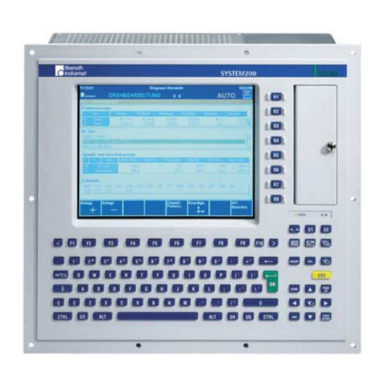
Page 31: Front Panel, Keyboard
BTV30.2 Front Panel, Keyboard Front Panel, Keyboard Floppy Disk Flap BTV30 BTV30 unlock external keyboard …P …P BTV30_2_Floppyklappe.fh7 Fig. 6-1: Unlocking the floppy disk flap and connector for external keyboard The floppy disk flap is locked by a quick release lock. To open the flap, rotate the locking knob by approximately 180°... -
Page 32: Status Indicators
Front Panel, Keyboard BTV30.2 Status Indicators Beneath the floppy disk flap, there are two red LEDs that have the following meanings: Power lights as soon as power is applied to the BTV30 unit and the unit has been switched on. lights up as soon as there is an access to the hard disk. -
Page 33: Explanation And Emulation Of The Special Keys
BTV30.2 Front Panel, Keyboard Explanation and Emulation of the Special Keys The keyboard of the BTV30.2 unit features 13 special keys that do not exist on a normal PC keyboard. These keys are listed in the following table. The list also specifies how these keys can be emulated on an external standard keyboard. -
Page 34: Keyboard Mouse
Front Panel, Keyboard BTV30.2 Keyboard Mouse The cursor block of the BTV30.2 unit can be switched over and be used for controlling mouse (only possible with Windows95 / NT) mouse/cursor selection INSERT PAGE HOME mouse click PAGE DOWN BTV30_2_Tastaturmaus.fh7 Fig. 6-5: Enlarged sectional view of the cursor block with the additional keys of the keyboard mouse Pressing the... -
Page 35: Machine Function Keys
BTV30.2 Front Panel, Keyboard Machine Function Keys machine function keys BTV30 …P BTV30_2_AdressenSoftkeys.fh7 Fig. 6-6: Enlarged sectional view of the machine function keys There are eight vertically arranged machine function keys to the right of the display. These keys are either connected directly to an integrated PLC of the MTS-P type, or are available at a 9-way socket (see Fig. -
Page 36: Fig. 6-7: Addressing The Machine Function Keys To Interface 19Vrs
Front Panel, Keyboard BTV30.2 To interface 19VRS Machine function keys Address %I0.1481.0 %I0.1481.1 %I0.1481.2 %I0.1481.3 %I0.1481.4 %I0.1481.5 %I0.1481.6 %I0.1481.7 Fig. 6-7: Addressing the machine function keys to interface 19VRS Further it is possible to use address constants for INDRAMAT firmware Alternative addressing with data types, instead of direct address specification. -
Page 37: Fig. 6-10:Addressing The Machine Function Keys As From Interface 21Vrs
BTV30.2 Front Panel, Keyboard On interface 21VRS As from software version 21VRS a logical number has to be assigned to each device as well as to all machine function keys. Use the IO editor of the programming interface to assign to the numbers (see Fig. 6-11). Depending on the application the device number can be different. - Page 38 Front Panel, Keyboard BTV30.2 DOK-MTC200-BTV30.2****-PR02-EN-P...
-
Page 39: Connection Pin Assignment
BTV30.2 Connection Pin Assignment Connection Pin Assignment General Connections 12 VDC power supply for BTM units, with 1.6A MT fuse LPT1 and SIS interface MTS-P MTC-P mains switch 3,1 A T mains connection 12 VDC OUT 3 A max. grounding stud M5 PC with Ehternet INTERBUS-S axis processor... -
Page 40: Interfaces Of The Btv30.2
Connection Pin Assignment BTV30.2 Interfaces of the BTV30.2 Interfaces of the Slot CPU Serial Interface COM1 Connector width max. 32 mm XGA / SVGA Screen Connection Ethernet Interface 10 Base-T Slot_CPU_Inside.fh7 Fig. 7-3: Location of the Interface Connectors Serial interface COM1 Signal name Signal name N.C. -
Page 41: Fig. 7-5: Pin Assignment Of The Svga Screen Connection
BTV30.2 Connection Pin Assignment SVGA screen connection Signal name Signal name Video Signal Red Video Signal Green Video Signal Blue N.C. DIG-GND ANA-GND ANA-GND ANA-GND DIG-GND N.C. DDCDAT HSYNC VSYNC DDCCLK Fig. 7-5: Pin assignment of the SVGA screen connection Ethernet interface (10 Base-T) 10Base_T.fh7 Fig. -
Page 42: Lpt1-Printer Port And Sis
Connection Pin Assignment BTV30.2 LPT1-Printer Port and SIS The both interfaces are lead out to a separate slot metal sheet. They are internal directly connected to the Slot CPU across an printed wiring board (PSU02). The serial interface COM2 (X16) is wired by Indramat standard (SIS). -
Page 43: Realisation Of The Btv30 Pc Version
BTV30.2 Connection Pin Assignment Realisation of the BTV30 PC version On the PC variant of the BTV30 unit, the unit only contains the CPU module. Controllers are not installed here. In the type code, this variant is identified by a "P" at position 4 (function type). In addition, the TM plug-in module is employed. - Page 44 Connection Pin Assignment BTV30.2 DOK-MTC200-BTV30.2****-PR02-EN-P...
-
Page 45: Application Example
BTV30.2 Application Example Application Example Networking Example for RS485 Communication SYSTEM200 BTV30 BTV30 System 00 RS485 MTC200-R IKB0017 RECO System 01 Q*.3.0 *.3.0 *.3.0 Q*.3.0 Q*.3.0 Q*.3.1 *.3.1 *.3.1 Q*.3.1 Q*.3.1 Q*.3.2 *.3.2 *.3.2 Q*.3.2 Q*.3.2 DIAG Q*.3.3 *.3.3 *.3.3 Q*.3.3 Q*.3.3 Q*.3.4... -
Page 46: Application Example For Interbus Connection
Application Example BTV30.2 Application Example for INTERBUS Connection SYSTEM200 BTV30 BTM15 BTM15 BTM15 BTM15 BTM15 10 20 75 80 BTV30 Emergency Stop IKS 0056 BTM15 NTER US - NTER US - NTER US - X 60 MTS-P ALARM NTER US - NTER US - NTER... -
Page 47: Application Example For Sercos Interface
BTV30.2 Application Example Application Example for SERCOS Interface SYSTEM200 BTV30 BTV30 Control panel BTV30 with integrated NC-Card MTC-P MTC-P Fibre obtic cable IKO0985/... Fibre obtic cable IKO0982/... Drive amplifier DIAX04 Supply module Max. 8 drive modules HVE or. HVR for each SERCOS fibre optic HDS or HDD App_diax04.fh7 Fig. - Page 48 Application Example BTV30.2 DOK-MTC200-BTV30.2****-PR02-EN-P...
-
Page 49: Slot-Cpu Card
BTV30.2 SLOT-CPU Card SLOT-CPU Card Performance Characteristics Inside_CPU.tif Fig. 9-1: Inside CPU Board 686LCD/MG • 64 Bit onboard Video Controller with 4 MB Video Ram • Flat Panel interface as well as standard VGA analogue monitors • RS232C or 1 x RS232C and 1 x RS422/485 serial interface channels, one parallel printer port, one EIDE compatible hard disk interface and one floppy disk controller for peripheral support •... -
Page 50: Technical Data
SLOT-CPU Card BTV30.2 Technical Data Electrical Specification Power Supply +5, +12 V (+/- 3%). Can operate at +5 volt only Power Consumption 10-20W typical (Dependent on processor type) Backup batteries +3.0 Volt Battery (CR2032, Lithium) Fig. 9-2: Electrical Specification CPU and Memory Specification AMD, K6 ΙΙΙ... -
Page 51: General Specifications
BTV30.2 SLOT-CPU Card General Specifications Dimensions 249.7 mm x 122.9 mm x 20.0-35.0 mm Ambient Conditions 0°C - 60°C operating temperature (forced cooling) 10% - 90% relative humidity (non-condensing) Plug and Play Features All configuration is done by software (Automatic or user-setup) Automatic processor type detection and setup. -
Page 52: Amibios Setup
SLOT-CPU Card BTV30.2 AMIBIOS Setup AMIBIOS Setup configures system information that is stored in CMOS RAM. AMIBIOS Setup has an easy-to-use graphical user interface that will be immediately recognisable to anyone who has ever used Microsoft Windows. This AMIBIOS Setup sets a new standard in BIOS user interfaces. -
Page 53: Amibios Setup Main Menu
BTV30.2 SLOT-CPU Card Alphabetic keys A to Z are used in the Virtual Keyboard, and are not case-sensitive. 0 to 9 are used in the Virtual Keyboard and Numeric Keypad. Fig. 9-6: AMIBIOS Key-Functions Automatic AMIBIOS Setup Option Selection If selecting a certain setting for a specific AMIBIOS Setup option that determines the settings for one or more other AMIBIOS Setup options, AMIBIOS automatically assigns the dependent settings and does not permit the end user to modify these settings unless the setting for the... -
Page 54: Setup Types
SLOT-CPU Card BTV30.2 Setup Types AMIBIOS Setup have six separate windows. Different types of system configuration parameters are set on each window. Type Description Standard Setup Set the time and date. Configure disk drives. Advanced Setup Configure basic system performance parameters. Chipset Setup Configure features specific to the onboard chipset. -
Page 55: Fig. 9-11:Advanced Setup
BTV30.2 SLOT-CPU Card Advanced Setup Quick Boot Disabled Boot Device Floppy Boot Device IDE-0 Boot Device CDROM Try Other Boot Devices PCMCIA ATA-HD support Disabled Display Mode at Add-On ROM Init Force BIOS Floppy Acces Control Read-Write Hard Disk Acces Control Read-Write S.M.A.R.T. -
Page 56: Fig. 9-12:Chipset Setup
SLOT-CPU Card BTV30.2 Chipset Setup USB Function Disabled USB Keyboard/Mouse Legacy Support Disabled USB Passive Release Enable Enabled Global Triton2 Enable Enabled Memory Hole Disabled 8Bit I/O Recovery Time (Sysclk) 16Bit I/O Recovery Time (Sysclk) DRAM Timings 70 ns Refresh Rate 66MHz Turbo Read LeadOff Disabled... -
Page 57: Fig. 9-13:Power Management Setup
BTV30.2 SLOT-CPU Card IRQ8 Ignore IRQ9 Ignore IRQ10 Ignore IRQ11 Ignore IRQ12 Both IRQ13 Ignore IRQ14 Monitor IRQ15 Monitor Fig. 9-13: Power Management Setup PCI / PnP Setup Plug and Play Aware O/S PCI Latency timer (PCI Clocks) PCI VGA Palette Snoop Disabled PCI IDE BusMaster Disabled... - Page 58 9-10 SLOT-CPU Card BTV30.2 Inside utilities Processor Clock (INT/EXT) 366/66MHz Secure CMOS Disabled Ethernet controller SCSI controller VGA controller Display Type CRT & Panel Panel driver 05h (Note 1) Panel Interface 5.0 V JPLCD PIN 5 GP02 Panel link adjustment SSD drive SSD prepare OnBoard FDC...
-
Page 59: Security
9-11 BTV30.2 SLOT-CPU Card Temperature violation action CPU Speed Fan overload limit, Act: 60mA Fan disconnect or overload action Speaker OnBoard IDE Primary Fig. 9-15: Inside utilities Note 1: Resolution: 640 x 480 Technology: TFT Color Manufacture: Toshiba Code: LTM10C209 Security Three icons appear in this part of the AMIBIOS Setup screen: •... -
Page 60: Default
9-12 SLOT-CPU Card BTV30.2 Changing a Password Select the Supervisor or User icon from the Security section of the AMIBIOS Setup main menu. Enter the password and press <Enter>. The screen does not display the characters entered. After the new password is entered, retype the new password as prompted and press <Enter>. -
Page 61: Amibios Power-On Self Test
9-13 BTV30.2 SLOT-CPU Card AMIBIOS Power-On Self Test Every time the system is powered on, AMIBIOS executes a power-on self test. In case of errors they are reported in one of two ways. If the error occurs before the display device is initialised, a series of beeps sound. Beep codes indicate that a fatal error has occurred. -
Page 62: Installation Of The Memory Module
9-14 SLOT-CPU Card BTV30.2 Installation of the Memory Module 1. The memory module is inserted to the mount (look to the figure below) To do this incline the module on 45°. 2. Tilt the module carefully on the mount to behind until it snap into position. -
Page 63: Ordering Information
10-1 BTV30.2 Ordering Information Ordering Information 10.1 Type Code Abbrev. Column 1 2 3 4 6 7 8 9 1 2 3 4 6 7 8 9 1 2 3 4 6 7 8 9 1 2 3 4 6 7 8 9 Example: B T V 3 0 . -
Page 64: 10.2 Configuration Type Codes
10-2 Ordering Information BTV30.2 10.2 Configuration Type Codes BTV30.2C Slot no. Abbrev. Column 1 2 3 4 6 7 8 9 1 2 3 4 6 7 8 9 1 2 3 4 6 7 8 9 1 2 3 4 6 7 8 9 Example: C F G - B T V 3 0 . -
Page 65: Btv30.2S
10-3 BTV30.2 Ordering Information BTV30.2S Slot no. Abbrev. Column 1 2 3 4 6 7 8 9 1 2 3 4 6 7 8 9 1 2 3 4 6 7 8 9 1 2 3 4 6 7 8 9 Example: C F G - B T V 3 0 . -
Page 66: Btv30.2E
10-4 Ordering Information BTV30.2 BTV30.2E Slot no. Abbrev. Column 1 2 3 4 6 7 8 9 1 2 3 4 6 7 8 9 1 2 3 4 6 7 8 9 1 2 3 4 6 7 8 9 Example: C F G - B T V 3 0 . -
Page 67: Btv30.2P
10-5 BTV30.2 Ordering Information BTV30.2P Slot no. Abbrev. Column 1 2 3 4 6 7 8 9 1 2 3 4 6 7 8 9 1 2 3 4 6 7 8 9 1 2 3 4 6 7 8 9 Example: C F G - B T V 3 0 . - Page 68 10-6 Ordering Information BTV30.2 DOK-MTC200-BTV30.2****-PR02-EN-P...
-
Page 69: Accessories
11-1 BTV30.2 Accessories Accessories 11.1 Connectors and Standard Cables Order designation of Matching connector of INDRAMAT cable Cable end type standard cables unit INS0525/L01 INS0526/L01 IKS0056/000,0 INK0234 MN: 255 968 (Interbus cable) 9pin./male 9pin./female INS0619/K01 INS0619/K01 IKB0017/000,0 INK0572 MN: 282 872 (RS485, max 400m) 15-way/male 15-way/male... -
Page 70: Standard Interface Connectors
11-2 Accessories BTV30.2 Standard Interface Connectors For the communication with RS422 and RS485 interfaces there are connectors with integrated termination resistors available (see Fig. 11-1). The cable can be mounted with a screw terminal. The figure below shows the connector pin assignments of the both connectors. INS0619/K01 INS0645/K01 RS485+... -
Page 71: 11.2 Ethernet Card Pcm-E01.1
11-3 BTV30.2 Accessories 11.2 Ethernet Card PCM-E01.1 PCM_E01.tiff Fig. 11-3: Ethernet card PCM-E01.1 The PCM-E01.1 is an Ethernet adapter with Plug & Play capability which is realized as PC plug-in card for the ISA bus. There are several possibilities to connect the Ethernet card to the network: •... -
Page 72: Technical Data
11-4 Accessories BTV30.2 Type Code Abbrev.- Column 1 2 3 4 6 7 8 9 1 2 3 4 6 7 8 9 1 2 3 4 6 7 8 9 1 2 3 4 6 7 8 9 Example: P C M - E 0 1 . -
Page 73: Elements On The Slot Sheet
11-5 BTV30.2 Accessories Elements on the Slot Sheet RJ45-Port AUI-Port BNC-Port Slotblech.fh7 Fig. 11-6: Connector PCM-E01.1 RJ45 port 10Base_T.fh7 Fig. 11-7: RJ45 port Signal name Signal name TxD + TxD - RxD + N.C. N.C. RxD - N.C. N.C. Fig. 11-8: Pin assignment of the RJ45 port DOK-MTC200-BTV30.2****-PR02-EN-P... -
Page 74: Fig. 11-9:Aui Port
11-6 Accessories BTV30.2 AUI port The AUI port is a 15 pin D-Sub female connector with sliding interlock. Aui.fh7 Fig. 11-9: AUI port Signal name Signal name Collision shield Collision - Collision + Transmit - Transmit + Transmit shield Receive shield Receive - Receive + + 12 V... -
Page 75: Installation
11-7 BTV30.2 Accessories Installation Hardware installation Note: The Ethernet card PCM_E01.1 is inserted when the card is delivered. Normally, a hardware installation is not necessary. In the case that the card has to be mounted or dismounted please proceed as follows: 1. -
Page 76: Fig. 11-12: Screen To Select The Ethernet Adapter
11-8 Accessories BTV30.2 3comadd.bmp Fig. 11-12: Screen to select the Ethernet adapter 8. Ensure that "Bus Type: ISA" and "Bus Number 0" is indicated and start the installation program with "OK". 3comadr.bmp Fig. 11-13: Screen to select the bus Select "Custom Installation" ("Next").. 10. -
Page 77: Fig. 11-14: Configuration Screen
11-9 BTV30.2 Accessories 3comcfg.bmp Fig. 11-14: Configuration screen 11. Carry out the NIC test. No error should be indicated (message: "Tests Complete") 12. The "Network Connection Test" should only be carried out, when the network functions of NT have already been installed. Otherwise, an error message is indicated. - Page 78 11-10 Accessories BTV30.2 DOK-MTC200-BTV30.2****-PR02-EN-P...
-
Page 79: Included Equipment
12-1 BTV30.2 Included Equipment Included Equipment Mounting set • 10 x tallow-drop screws M5 x 12 • 10 x gaskets M5 Nyltite • 1 x 3 way cable female connector • Front plate gasket 404 x 4 x 0,8 mm •... - Page 80 12-2 Included Equipment BTV30.2 DOK-MTC200-BTV30.2****-PR02-EN-P...
-
Page 81: List Of Figures
13-1 BTV30.2 List of Figures List of Figures Fig. 1-1: BTV30.2 front panel 1-1 Fig. 3-1: Hazard classification (according to ANSI Z535) 3-1 Fig. 4-1: Specification of the Power Supply Unit 4-2 Fig. 4-2: Ambient Conditions BTV30.2 4-2 Fig. 4-3: HDD load 4-3 Fig. - Page 82 13-2 List of Figures BTV30.2 Fig. 9-5: General Specifications 9-3 Fig. 9-6: AMIBIOS Key-Functions 9-5 Fig. 9-7: AMIBIOS Setup Main Menu 9-5 Fig. 9-8: Setup Types 9-6 Fig. 9-9: Standard Setup 9-6 Fig. 9-10:Primary Master Hard Disk 9-6 Fig. 9-11:Advanced Setup 9-7 Fig.
-
Page 83: Index
14-1 BTV30.2 Index Index Address constants 6-6 Advanced Setup 9-7 Air pressure 4-2 Ambient Conditions 4-2 AMIBIOS Key-Functions 9-5 AMIBIOS Setup 9-4 Appropriate use Area of application 2-2 Introduction 2-1 Uses 2-2 AUI port 11-6 Backlight tubes 4-3 Beep Codes 9-13 BNC port 11-6 BTV30.2C 10-2 Cable accessories 11-1... - Page 84 14-2 Index BTV30.2 Interface Connectors 7-2 Interfaces 4-1 Keyboard 4-1 LED display 11-6 LPT1 7-4 Main Memory 4-1 Main Menu 9-5 Max. ambient temperature 4-2 Max. external magnetic field 4-2 Max. shock 4-2 Max. temperature gradient 4-2 Max. vibration 4-2 Modules 1-2 Mounting dimensions 5-4 NC controller 1-1...
- Page 85 14-3 BTV30.2 Index Technical data 4-1 PCM-E01 11-4 Technical Data Ambient Conditions 4-2 General 4-1 Slot CPU Card 9-2 TM 7-5 Type code 10-1 Type code PCM-E01 11-4 Use See appropriate use and inappropriate use User Password 9-11 Weight 4-1 DOK-MTC200-BTV30.2****-PR02-EN-P...
- Page 86 14-4 Index BTV30.2 DOK-MTC200-BTV30.2****-PR02-EN-P...
-
Page 87: Service & Support
15-1 BTV30.2 Service & Support Service & Support 15.1 Helpdesk Unser Kundendienst-Helpdesk im Hauptwerk Lohr Our service helpdesk at our headquarters in Lohr am am Main steht Ihnen mit Rat und Tat zur Seite. Main, Germany can assist you in all kinds of inquiries. Sie erreichen uns Contact us +49 (0) 9352 40 50 60... -
Page 88: 15.5 Kundenbetreuungsstellen - Sales & Service Facilities
15-2 Service & Support BTV30.2 15.5 Kundenbetreuungsstellen - Sales & Service Facilities Deutschland – Germany vom Ausland: (0) nach Landeskennziffer weglassen! from abroad: don’t dial (0) after country code! Vertriebsgebiet Mitte Germany Centre S E R V I C E S E R V I C E S E R V I C E C A L L E N T R Y C E N T E R... - Page 89 - service: +34 9 43 31 84 60 satindramat-goimendi@adegi.es Sweden - Schweden Switzerland West - Schweiz West Switzerland East - Schweiz Ost Rexroth Mecman Svenska AB Bosch Rexroth Suisse SA Bosch Rexroth Schweiz AG Indramat Support Département Rexroth Indramat Geschäftsbereich Indramat Ekvändan 7...
- Page 90 15-4 Service & Support BTV30.2 Europa (Ost) - Europe (East) vom Ausland: (0) nach Landeskennziffer weglassen from abroad: don’t dial (0) after country code Czech Republic - Tschechien Czech Republic - Tschechien Hungary - Ungarn Poland – Polen Mannesmann-Rexroth, spol.s.r.o. DEL a.s.
- Page 91 (0) after country code! Australia - Australien Australia - Australien China China AIMS - Australian Industrial Bosch Rexroth Pty. Ltd. Shanghai Mannesmann Rexroth Mannesmann Rexroth (China) Ltd. Machinery Services Pty. Ltd. No. 7, Endeavour Way Hydraulics & Automation Ltd.
- Page 92 Fax: +1 860 8 44 85 95 Fax: +1 925 227 10 81 Canada East - Kanada Ost Canada West - Kanada West Bosch Rexroth Corporation Bosch Rexroth Burnaby Burlington Division 5345 Goring St. 3426 Mainway Drive Burnaby, British Columbia...
- Page 94 2 8 2 2 7 5...