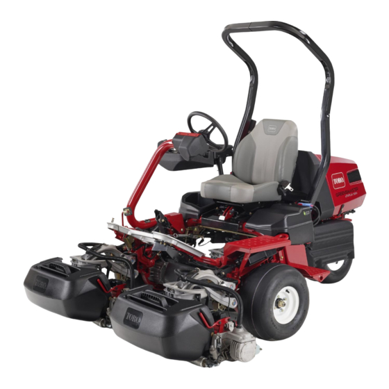
Toro Greensmaster eTriFlex 3370 Operator's Manual
Traction unit
Hide thumbs
Also See for Greensmaster eTriFlex 3370:
- Service manual (331 pages) ,
- Service manual (366 pages) ,
- Operator's manual (60 pages)

Related Manuals for Toro Greensmaster eTriFlex 3370


Summary of Contents for Toro Greensmaster eTriFlex 3370
- Page 1 Form No. 3439-773 Rev B Greensmaster ® eTriFlex 3370 Traction Unit Model No. 04590—Serial No. 400000000 and Up *3439-773* Register at www.Toro.com. Original Instructions (EN)
- Page 2 This manual uses 2 words to highlight information. Important calls attention to special mechanical Whenever you need service, genuine Toro parts, or information and Note emphasizes general information additional information, contact an authorized Toro worthy of special attention.
-
Page 3: Table Of Contents
Contents Recommended Maintenance Schedule(s) ... 37 Daily Maintenance Checklist......38 Pre-Maintenance Procedures ......38 Safety ............... 4 Raising the Machine ......... 38 General Safety........... 4 Raising the Hood ..........40 Safety and Instructional Decals ......4 Electrical System Maintenance ......40 Setup ................ -
Page 4: Safety
Safety and Instructional Safety Decals This machine has been designed in accordance with EN ISO 5395 (when you complete the setup Safety decals and instructions are procedures) and ANSI B71.4-2017. easily visible to the operator and are located near any area of potential danger. - Page 5 decal133-8061 133-8061 decal137-8127 137-8127 1. Attention—do not spray with high-pressure water. decal137-8037 137-8037 1. Read the Operator’s 4. Cutting unit—3 Manual for fuse information. decal137-9712 137-9712 2. Cutting unit—1 5. 3-wheel-drive kit 3. Cutting unit—2 1. Warning—read the 3. Explosion hazard—do not Operator’s Manual.
- Page 6 decal139-8320 decal139-8321 139-8320 139-8321 Note: This machine complies with the industry standard 1. Warning—all operators 4. Warning; tipping stability test in the static lateral and longitudinal tests with the should read the Operator’s hazard—drive slowly maximum recommended slope indicated on the decal. Review the Manual and be trained when turning;...
- Page 7 139-8554 Operator’s Manual. power connectors, connect the battery to 1. Warning—Use Toro 04012, Delta-Q 951-0002, or equivalent the charging connector charger only; Store machine indoors. and do not operate the machine, disconnect the battery from the charging...
-
Page 8: Setup
Steering wheel Install the steering wheel. Washer Locknut Grass-basket hook Install the grass-basket hooks. Flange bolts Cutting unit (order separately; contact your authorized Toro distributor) Grass basket Install the cutting units. Electric counterweight Capscrew O-ring – No parts required Connect the main-power connectors. -
Page 9: Installing The Roll Bar
Hex-head bolt (3/8 x 1-1/2 inch) Nut (3/8 inch) Procedure Procedure Acquire the Seat Kit (contact your authorized Toro distributor) and refer to the kit Installation Instructions Remove the top crate support from the crate. to install the seat. Remove the roll bar from the crate. -
Page 10: Installing The Steering Wheel
Insert the key and turn it to the O position. Navigate to the traction information screen in the InfoCenter; refer to Using the InfoCenter LCD Display (page 16). Turn the steering wheel until the steering-wheel angle (located at the bottom of the screen) reads “0°”. -
Page 11: Installing The Grass-Basket Hooks
Installing the Cutting Units Parts needed for this procedure: Cutting unit (order separately; contact your authorized Toro distributor) Grass basket g010834 Figure 8 Electric counterweight Capscrew 1. Steering wheel 3. Locknut 2. Washer 4. Cap O-ring Torque the locknut to 27 to 35 N∙m (20 to 26 Procedure ft-lb). -
Page 12: Connecting The Main-Power Connectors
g036342 Figure 11 1. Capscrew 3. Existing counterweight 2. Electrical counterweight g293202 Install the cutting units; refer to Installing the Figure 12 Cutting Units (page 47). 1. Main-power connectors Install each grass basket onto the grass-basket hooks. Adjusting the Machine Connecting the Main-Power Settings Connectors... -
Page 13: Installing The Ce Decals
Installing the CE Decals If Required (CE-Compliant Countries) g235881 Figure 14 Parts needed for this procedure: 1. CE warning decal Production year decal CE warning decal (Part No. 139-8321) CE mark decal (Part No. 93-7252) Procedure Reducing the Tire Pressure If you use this machine in a country that complies to CE standards, install the following decals: •... -
Page 14: Charging The Batteries
Product Overview Charging the Batteries No Parts Required Procedure Charge the batteries; refer to Charging the Lithium-Ion Batteries (page 35). g289915 Figure 15 1. Grass basket 6. Operator’s seat 2. Traction pedal 7. Roll bar 3. Brake pedal 8. Hood 4. -
Page 15: Controls
Controls You can shift from M to T or T RANSPORT RANSPORT to M (not to N ) while the machine is in EUTRAL motion; no damage will result You can move the switch from T or M RANSPORT to N and the machine will come to a stop. -
Page 16: Infocenter
g236365 Figure 20 1. Parking brake 2. Brake pedal g014603 Figure 18 Parking Brake 1. Traction pedal—forward 3. Steering-arm-locking pedal Use the parking brake (Figure 20) to prevent the 2. Traction pedal—reverse machine from moving. To engage the parking brake, push down on the brake pedal and press the top forward to latch. - Page 17 g292767 Figure 22 1. Front left cutting motor 3. Center cutting-unit motor 2. Front right cutting-unit motor • Traction information screen (Figure 23): g020650 shows the current steering angle and the Figure 24 amperage allotted to each traction motor. 1. Indicator light 3.
- Page 18 AULTS AULTS a list of the recent machine Key switch faults. Refer to the Service Manual or your authorized PIN code Toro distributor for more information on the F AULTS menu. CAN bus The S menu contains ERVICE...
- Page 19 Service Settings (cont'd.) Menu Item Description Lists the total number of OURS Sets the maximum machine hours that the key, reels, and EVERSE speed while moving the backlap have been on. machine in reverse. Lists the number of mows, OUNTS Enables or disables the slow tap-offs, and backlaps.
- Page 20 0000 or 1234. authorized Toro distributor. If you changed the PIN code and forgot the code, contact your authorized Toro distributor for assistance. Understanding the Fault-Log Indicator From the M , use the center button to...
-
Page 21: Specifications
g293203 Figure 25 1. Main-power connectors CAUTION If you do not disconnect the power to the machine, someone could accidentally turn on the machine, causing serious bodily injury. Always separate the connectors before working on the machine. Specifications g289936 Figure 26 Refer to Figure 26 and the... -
Page 22: Attachments/Accessories
Contact may restrict the age of the operator. The owner your Authorized Service Dealer or authorized Toro is responsible for training all operators and distributor or go to www.Toro.com or a list of all mechanics. approved attachments and accessories. •... -
Page 23: Using The Infocenter To Adjust The Machine Settings
• Disabling an equipped 3-Wheel-Drive Kit; refer Disabling an Equipped 3-Wheel-Drive Kit (page 25). • Battery-reserve capacity; refer to Setting the Battery-Reserve Capacity (page 25). Note: Each setting is passcode-protected. You may need to enter a passcode to edit the settings. Adjusting the Tap-Off Delay Navigate to the T option to adjust the... - Page 24 greater the difference in reel speeds. Additionally, if Mowing Reel Speed Options (cont'd.) the machine speed changes while you are cutting, the RDS system adjusts the reel speed to maintain a constant clip. This feature reduces turf thinning on 1550 the inside reel (in comparison to other riding greens mowers), which can reduce triplex ring.
-
Page 25: Understanding The Infocenter Dialog Messages
Adjusting the Maximum Transport Understanding the Speed InfoCenter Dialog Navigate to the M option to adjust the RANSPORT Messages maximum transport speed. You can adjust the speed from 8.0 km/h (5.0 mph) to 16.0 km/h (10.0 mph) in When the machine is being calibrated, dialog increments of 0.8 km/h (0.5 mph). -
Page 26: Tilting The Steering Wheel
• Check the reel-to-bedknife contact; refer to Dialog Messages (cont'd.) Checking the Reel-to-Bedknife Contact (page 49). • Check the tire pressure; refer to Checking the Tire Pressure (page 44). Wait for wheels to stop • Check the safety-interlock system; refer to Move pedal to max forward and hold Checking the Safety-Interlock System (page 28). -
Page 27: Breaking In The Machine
• Do not leave an activated machine unattended. Tall grass can hide obstructions. Uneven terrain could overturn the machine. • Before you leave the operating position, do the • following: Be aware that operating the machine on wet grass, across slopes, or downhill may cause the –... -
Page 28: Understanding The Safety-Interlock System
The cutting reels should stop rotating and the system is operating correctly. Correct the problem cutting units should raise to the full transport if it is not operating properly. position. • Sit in the seat, turn on the machine, disengage the parking brake, move the function-control switch Understanding the to the N... - Page 29 Note: This holds compaction to a minimum and requiring you to release pressure on the traction leaves a neat, attractive pattern on the greens. pedal. Move the function-control switch to the M position. Push forward the lift/lower mow lever as the front edges of the grass baskets cross the outer edge of the green.
-
Page 30: Monitoring The Battery-System Charge Level
Cutting the Periphery and machine to a designated battery-charging area and charge the batteries; refer to Charging the Finishing the Job Lithium-Ion Batteries (page 35). Finish cutting the green by mowing the outer periphery. Change the direction of cutting from Shutting Off the Machine the previous mowing. - Page 31 Toro • Refer to an authorized Toro distributor to service distributor for a replacement. or replace a battery. • Unplug the charger from the electrical outlet when...
-
Page 32: Inspecting And Cleaning After Mowing
Inspecting and Cleaning Hauling the Machine after Mowing • Use care when loading or unloading the machine into a trailer or a truck. After mowing, thoroughly wash the machine with • Use a full-width ramp for loading the machine into a garden hose without a nozzle so that excessive a trailer or a truck. -
Page 33: Towing The Machine
Towing the Machine DANGER When the actuator is released from the Note: Refer to Figure 32 for this procedure. brake, the machine is able to free wheel. A free-wheeling machine can cause serious injury to bystanders. If the machine is not being towed, engage the parking brake. -
Page 34: Maintaining The Lithium-Ion Batteries
For detailed information on shipping a battery, contact drops below -30°C (-22°F) or rises above 60°C your authorized Toro distributor. (140°F). Temperatures outside of this range will damage your batteries. High temperatures during storage, especially at a high state of charge, reduces the life of the batteries. -
Page 35: Understanding The Lithium-Ion Battery Charger
3. AC Power indicator light 8. Output connector and cord Attempting to charge the batteries with a 4. Battery-charging indicator 9. Power-supply cord charger not provided by Toro can result in light excessive heat and other related product 5. Charging-output indicator light malfunctions, which can lead to property damage and/or injury. - Page 36 To correct an error, refer to Troubleshooting (page 52). debris. If none of these solutions correct the issue, contact an Slide the charger-output connector into the authorized Toro distributor. charger connector on the machine (Figure 35). Note: The machine connector is located below...
-
Page 37: Maintenance
– Engage the parking brake. • To ensure safe, optimal performance of the machine, use only genuine Toro replacement – Shut off the machine and remove the key. parts. Replacement parts made by other – Wait for all movement to stop. -
Page 38: Daily Maintenance Checklist
Daily Maintenance Checklist Duplicate this page for routine use. For the week of: Maintenance Check Item Mon. Tues. Wed. Thurs. Fri. Sat. Sun. Check the safety-interlock operation. Check the instrument operation. Check the brake operation. Check the tire pressure. Check the reel-to-bedknife contact. - Page 39 g286954 Figure 36 1. Foot step—left side of the machine 3. Jack bracket—right side of the machine 2. Caster fork—rear of the machine After raising the machine, use an appropriate jack stand under the following areas to support the machine (Figure 37): •...
-
Page 40: Raising The Hood
Raising the Hood Electrical System Maintenance Release the straps from each side of the hood (Figure 38). Electrical System Safety • Disconnect the main-power connectors before repairing the machine. • Charge the battery in an open, well-ventilated area, away from sparks and flames. Unplug the charger before connecting or disconnecting the battery. -
Page 41: Locating The Fuses
Locating the Fuses Locating the 48 V-System Fuses The fuses in the 48 V electrical system are located under the seat (Figure 39). g279712 Figure 40 1. Right-side cover 2. Bolt Refer to Figure 41 for a description of each fuse on the fuse blocks: g288685 Figure 39... - Page 42 Locating the Reel-Drive Circuit Locating the Precharge Controller Fuses Fuse The fuses for the reel-drive circuit are located under The fuse that protects the precharge controller is the cover on the left side of the machine. Access the located in its own holder on the machine wire harness fuse block by removing the left-side cover and the to the left of the center (rear) battery set (Figure...
-
Page 43: Servicing The Batteries
A lithium-ion battery must be disposed of or recycled in accordance with local and federal regulations. If a battery requires service, contact your authorized Toro distributor for assistance. The only user serviceable parts on a battery are the labels. If you attempt to open the main compartment of a battery, you will void your warranty. -
Page 44: Drive System Maintenance
Changing the Drive System Traction-Motor-Gearbox Maintenance Fluid Checking the Tire Pressure Service Interval: After the first 8 hours Every 800 hours Service Interval: Before each use or daily Fluid specification: SAE 80W90 Vary the tire pressure for all 3 wheels, depending upon your turf conditions, from a minimum of 83 to a Gearbox oil capacity: approximately 384 ml (13 fl oz) maximum of 110 kPa (12 psi to 16 psi). - Page 45 g322517 Figure 50 g322518 Left side of the machine shown Figure 51 1. Drain port 3. Pan 1. Vent hose and fitting 2. Fill port 2. Drain plug Fill the gearbox with 384 ml (13 fl oz) of the Remove the plug from the drain port (Figure 50).
-
Page 46: Brake Maintenance
A worn or damaged blade or bedknife can break, and you can adjust the brakes; contact your authorized a piece could be thrown toward you or bystanders, Toro distributor or refer to the Service Manual for more resulting in serious personal injury or death. information. - Page 47 Installing the Cutting Units Open the latches on the suspension-arm bar (Figure 54) and push the suspension arm down The suspension needs to be lowered in order to install so that the bar fits over both pitch arms on the cutting units. Perform the following steps to lower the cutting unit and ensure that the latches go the suspension: underneath the cutting-unit crossbar...
- Page 48 CAUTION If you do not disconnect the power to the machine, someone could accidentally start the cutting units, causing serious injury to hands and feet. Always separate the disconnect the main-power connectors before working on the cutting units. Push the motor retaining bar out of the slots on the motor toward the cutting unit and remove the motor from the cutting unit.
-
Page 49: Checking The Reel-To-Bedknife Contact
Important: Do not raise the suspension to Insert the key into the switch and turn on the the transport position when the reel motors machine. are in the holders in the machine frame. On the InfoCenter control, from the S ERVICE Damage to the motors or wires could result. -
Page 50: Storage
Battery Storage Storage Requirements If you wish to store the machine for a long period Note: of time, perform the steps listed in Preparing the You do not need to remove the batteries from Machine for Storage (page 50). the machine for storage. Refer to the temperature requirements for storage in Storage Safety the following table:... -
Page 51: Storing The Charger
Examine the charger thoroughly for worn, loose, or damaged parts. To repair or replace parts, contact your authorized Toro distributor for assistance. Store the charger with the power supply cord in a clean, dry place where it will not be bumped or... -
Page 52: Troubleshooting
Code E-0-0-4 1. BMS or battery fault detected 1. Contact an authorized Toro distributor. Code E-0-0-7 1. Battery amp hour limit exceeded 1. Possible causes include poor battery health, very deeply discharged battery,... - Page 53 The Toro Company (“Toro”) respects your privacy. When you purchase our products, we may collect certain personal information about you, either directly from you or through your local Toro company or dealer. Toro uses this information to fulfil contractual obligations - such as to register your warranty, process your warranty claim or to contact you in the event of a product recall - and for legitimate business purposes - such as to gauge customer satisfaction, improve our products or provide you with product information which may be of interest.
- Page 54 4 years Battery Limited Warranty Battery The rechargeable Lithium-Ion battery is warranted to be free from defects in materials and workmanship for a period of 4 years. Over time, battery consumption reduces the amount of energy capacity (Amp-hours) available per full charge. Energy consumption varies due to operating characteristics, accessories, turf, terrain, adjustments, and temperature.
- Page 55 Countries Other than the United States or Canada Customers who have purchased Toro products exported from the United States or Canada should contact their Toro Distributor (Dealer) to obtain guarantee policies for your country, province, or state. If for any reason you are dissatisfied with your Distributor's service or have difficulty obtaining guarantee information, contact your Authorized Toro Service Center.
- Page 56 While the exposure from Toro products may be negligible or well within the “no significant risk” range, out of an abundance of caution, Toro has elected to provide the Prop 65 warnings. Moreover, if Toro does not provide these warnings, it could be sued by the State of California or by private parties seeking to enforce Prop 65 and subject to substantial penalties.