Table of Contents
Advertisement
Quick Links
MESSRS.
TECHNICAL REFERENCE
MODEL
Product name:
Product number:
Received by:
Motor Company., Matsushita Electric Industrial Co., Ltd.
7-1-1, Morofuku, Daito, Osaka, Japan 574-0044
Dept.
Checked
manager
AC Servo Amplifier
MINAS-A4P I/O Command Type
Issued on Feb.3, 2006
(Revised on
Date:
Checked
Designed
No. SR-DSV09485
)
Advertisement
Table of Contents

Related Manuals for Panasonic MINAS-A4P


Summary of Contents for Panasonic MINAS-A4P
- Page 1 No. SR-DSV09485 MESSRS. TECHNICAL REFERENCE MODEL Product name: AC Servo Amplifier Product number: MINAS-A4P I/O Command Type Issued on Feb.3, 2006 (Revised on Received by: Date: Motor Company., Matsushita Electric Industrial Co., Ltd. 7-1-1, Morofuku, Daito, Osaka, Japan 574-0044 Dept.
- Page 2 No. SR-DSV09485 REVISIONS Page REVISION Signed Date MOTOR COMPANY, MATSUSHITA ELECTRIC INDUSTRIAL CO.,LTD.
-
Page 3: Table Of Contents
No. SR-DSV09485 Contents Model Designation Code ............................1 Outer dimensions ..............................1 Appearance and Part Names ..........................2 Configuration of Connectors and Terminal Block Power Connectors X1 , X2 , and Terminal Block.................. 5 Encoder Connector X6 .......................... 5 Interface Connector X5 ......................... - Page 4 No. SR-DSV09485 11. Tuning 11-1 Real time Auto Gain Tuning........................92 11-2 Normal Mode Auto Gain Tuning........................ 96 11-3 Disabling of Auto Tuning Function......................99 11-4 Manual Gain Tuning..........................100 11-5 Frequency characteristics ......................... 114 12. Control Block Diagrams ........................... 115 13.
-
Page 5: Model Designation Code
No. SR-DSV09485 -(117-1)- Model Designation Code Notation of the machine designation code is as follows: Custom specification Type (Alphanumeric two digits) A: A4 Series Type A B: A4 Series Type B Interfacce specification C: A4 Series Type C P:Position command type D: A4 Series Type D E: A4 Series Type E Current rating... -
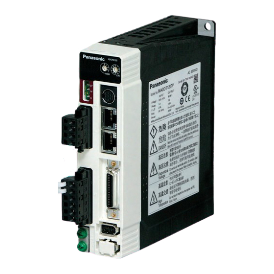
Page 6: Appearance And Part Names
No. SR-DSV09485 Appearance and Part Names A4 Series Type A, B MSD, LSD: Node address Name Label Rotary Switch SP: Velocity Monitor IM: Torque Monitor X4: RS232 Interface G: signal ground Connection (Pin 4) X1: Power Input Connection (Cable side) (Pin 3) X3A: RX Connection (Pin 2) - Page 7 No. SR-DSV09485 A4 Series Type C, D MSD, LSD: Node address Name Label Rotary Switch SP: Velocity Monitor IM: Torque Monitor X4: RS232 Interface G: signal ground Connection (Pin 5) X1: Power Input Connection (Pin 4) X3A: RX Connection (Pin 3) (Pin 2) (Pin 1) X3B: TX Connection...
- Page 8 No. SR-DSV09485 A4 Series Type E, F MOTOR COMPANY, MATSUSHITA ELECTRIC INDUSTRIAL CO.,LTD...
-
Page 9: Configuration Of Connectors And Terminal Block
No. SR-DSV09485 - 5 - Configuration of Connectors and Terminal Block Power Connectors X1 , X2 , and Terminal Block Terminal Marking Terminal Name Description Connectors Block Type A/B Type C/D Type E/F 100 V 100 to 115 V , 50/60 Hz input for L1 and L3 terminals. −... -
Page 10: Interface Connector X5
No. SR-DSV09485 - 6 - Interface Connector (Molex 529863679) Common input signals and their functions Connector Application Code Function signal pin No. interface - Connected to the [+] terminal of an external DC power supply (12 to 24 V) COM+ - Use a 12 V (±5%) to 24 V (±5%) power supply. - Page 11 No. SR-DSV09485 - 7 - I/O signal Connector Application Code Function pin No. interface Multi-function input Function can be selected and set by Servo parameter No 5A and 5C EX-IN1 out of the options below. Instantaneous stop, temporary stop, deceleration stop, high-speed Multi-function input normal rotation jog, high-speed reverse rotation jog, and alarm EX-IN2...
- Page 12 No. SR-DSV09485 - 8 - Output signal (pulse train) and function Connector I/O signal Application Code Function pin No. interface - Division-processed encoder signal or external scale signal (A/B-phase) is output in differential mode. (RS422) - Servo parameter No.44 (numerator of output pulse ratio) and Servo parameter A-phase output No.45 (denominator of output pulse ratio) can be used to set the division ratio.
- Page 13 No. SR-DSV09485 - 9 - I/O signal interface i – 1 o – 1 4.7K + R 50 mA or less 12-24V 12-24V +:37, 35, 39, 11 ピン, −:36, 34, 38, 10 ピン +: Pins 15, 27, 28 and 36 注) リレーを直接駆動する場合は、リレーと並列に NOTE) To activate the relay directly, connect a diode ...
-
Page 14: Rs232C Communication Connector X4
No. SR-DSV09485 - 10 - RS232C Communication Connector (JST MD-S8000-10 or equivalent) Parameter setting/alteration, control status monitoring, error status/record reference and parameter saving/loading etc. are available by means of a serial communication with a PC or console via RS232C or equivalent. Also, setup support software PANATERM and communication cable are available. -
Page 15: Analogue Monitor Pin
No. SR-DSV09485 - 11 - Analogue monitor pin (SP and IM) Application Code Description - The meaning of output signal depends on Servo parameter No.07 (speed monitor (SP) selection). Servo Meaning of Function parameter signal No.07 - Voltage in proportion to motor revolution speed is output Motor together with polarity. -
Page 16: Wiring
No. SR-DSV09485 - 12 - Wiring Cables Specifications and Maximum Cable Length Maximum Name Code Specifications cable length Conforms to "Specifications by Model" on Main power supply L1, L2, L3 ----- separate sheets. Control power supply L1C, L2C/r, t ----- HVSF 0.75mm Conforms to "Specifications by Model"... -
Page 17: Precautions For Wiring
No. SR-DSV09485 - 13 - Precautions for Wiring (1) Connecting cables to the power connectors and the terminal block Type A to Type B MC サージアブソーバ Surge absorber ノ 単相 100V X1 フ イ ィ ズ Single-phase 100 V or または ... - Page 18 No. SR-DSV09485 - 14 - Type C to Type D 単相 200V Single-phase 200 V MC - To use a single-phase power supply, be sure to connect the power supply *単相電源でご使用の場合は サージアブソーバ Surge absorber between the L1 and L3 terminals. ...
- Page 19 No. SR-DSV09485 - 15 - Type E to Type F Surge absorber サージアブソーバ ノ フ イ Main power ィ ズ 三相 3-phase 主電源 supply ル 200 V 200V タ r Control 制御電源 t power supply P Normally connected 通常接続 External regenerative 外付回生抵抗...
- Page 20 No. SR-DSV09485 - 16 - When using the servo amplifier in type C and D by using a single phase power input, connect it with L1 and L3 of the main power input terminal. Do not make any connection with L2 terminal. To connect a cable to each terminal on the terminal block, be sure to use crimp terminals with insulation shield.
- Page 21 No. SR-DSV09485 - 17 - Specifications Rated power Built-in Option Manufacturer Resist Thermal protector Free value part code model Temperature of operation Ω 1m/s 2m/s 3m/s DV0P4280 RF70M 140±5℃ DV0P4281 RF70M B-contact DV0P4282 RF180B Open/close capacity DV0P4283 RF180B (Resistive load) 4A 125VAC 10,000times DV0P4284 RF240...
- Page 22 No. SR-DSV09485 - 18 - <Connecting cables to the terminal block> Connect cables to the power connectors according to the following the procedure. Wiring procedure Unsheathe the cable to be used. 8 - 9 mm Plug the cable in the connector. To plug the cable, the following two methods are available: Insert the cable by using the supplied operation lever.
- Page 23 No. SR-DSV09485 - 19 - (2) Connecting cables to connector The 12 to 24 V DC control signal power supply for external control connected between the COM+ and COM- terminals should be prepared by the user. Place the servo amplifier and peripheral equipment at the shortest distance as possible (3 m or less), to minimize the connection cable length.
- Page 24 No. SR-DSV09485 - 20 - Control output Be careful of the polarity of the control signal power supply. Connecting the power supply with reverse polarities will damage the servo amplifier. (See the figure above). To activate the relay directly with each output signal, be sure to connect a diode in parallel with the relay, in the direction shown below.
- Page 25 No. SR-DSV09485 - 21 - Rotary encoder feedback pulse AM26C32 相当品 AM26C31 相当品 AM26C32 or equivalent AM26C31 or equivalent 分 周 処 理 回 路 ツイストペア Twisted pair cable Servo amplifier side サーボアンプ側 CN X5 NOTE) Only the Z-phase signal will be output through the line driver interface, and also output from Pin 16 (CZ) of the open-collector interface.
- Page 26 No. SR-DSV09485 - 22 - (3) Connecting cables to connector For the encoder cable, use a shielded twisted pair cable with strand core size of 0.18 mm or more. The allowable cable length is 20 m max. To use a long cable for the 5 V power supply, double-wiring is recommended to reduce the influence of a voltage drop.
- Page 27 No. SR-DSV09485 - 23 - 5-core incremental encoder 1 0V 2 3 White 4 Black 5 6 Light blue Purple Shielded cable Twisted pair cable 172168-1 172160-1 Manufactured by Tyco Manufactured by Tyco ...
- Page 28 No. SR-DSV09485 - 24 - (4) Connecting cables to connector For external scale cables, use a shielded twisted pair cables with strand core size of 0.18mm or more. The allowable cable length is 20 m max. To use a long cable for the 5 V power supply, double-wiring is recommended to reduce the influence of a voltage drop.
- Page 29 No. SR-DSV09485 - 25 - <Battery replacement procedure> The data read by the absolute encoder include the single-revolution data that indicate the motor position per revolution, and the multi-revolution data that indicate a pulse count per revolution. Since the multi-revolution data are electrically counted, they will be backed up with a battery. Leave the control power supply on during battery replacement.
-
Page 30: Parameters
No. SR-DSV09485 - 26 - Parameters Note 1) As for item having parameter No. marked with (*), altered data is enabled after resetting of the control power. Note 2) As for item having parameter No. marked with (RT), data is altered automatically while executing real time auto gain tuning. - Page 31 No. SR-DSV09485 - 27 - Parameter Related Setting Parameter Name Function/Description control mode range Select the output of the analog speed monitor (Front panel). Speed monitor The value given in ( ) indicates the monitor value at approx. 6 V. P, F 0 - 9 (SP) selection...
- Page 32 No. SR-DSV09485 - 28 - Parameter Parameter Related control Setting Function/Description Name mode range Defines the position loop gain. The unit is [1/s]. 1st position As the gain is increased, the servo stiffness in the position control mode is increased. P, F 0 - 3000 (RT)
- Page 33 No. SR-DSV09485 - 29 - Parameter Parameter Related control Setting Function/Description Name mode range Defines the ratio of load inertia to the motor's rotor inertia. The unit is [%]. Set value [%] = (Load inertia/ rotor inertia) × 100 Inertia ratio P, F 0 - 10000 (RT)
- Page 34 No. SR-DSV09485 - 30 - Parameter Related Setting Parameter Name Function/Description control mode range 2nd notch depth Select the notch depth of the second resonance suppression notch filter. 0 - 99 selection Increasing the set value reduces the notch depth and the phase delay. Vibration suppression frequency of the vibration suppression for suppressing vibration at the front end of a load is set.
- Page 35 No. SR-DSV09485 - 31 - Parameter Related Setting Parameter Name Function/Description control mode range Set up this parameter when the gain switching function is used for the optimum tuning. 0: Uses the first gain (Servo parameter No. 10 - 14). 2nd gain action set P, F 0 - 1...
- Page 36 No. SR-DSV09485 - 32 - Related Parameter Parameter Setting control Function/Description Name range mode Used by manufacturer Used by manufacturer Used by manufacturer Used by manufacturer Numerator of P, F 1 – 32767 Defines the number of pulses from the pulse output (X5 OA+: Pin 11, OA-: Pin 12, OB+: output pulse Pin 13 and OB-: Pin 14).
- Page 37 No. SR-DSV09485 - 33 - Related Parameter Parameter Setting control Function/Description Name range mode Defines the phase B logic and output source of the pulse output (X5 OB+: Pin 13 and OB-: Pin 14). 0: phase B output logic not inversed. 1: phase B output logic inversed (encoder). 2: phase B output logic not inversed.
- Page 38 No. SR-DSV09485 - 34 - Parameter Related Setting Parameter Name Function/Description control mode range Used by manufacturer Used by manufacturer Used by manufacturer Setting valid/invalid of CW/CCW over-travel inhibit input ( X5 CWL: Pin 20, Over-travel inhibit CCWL: Pin 19) P, F 0 - 1 input valid...
- Page 39 No. SR-DSV09485 - 35 - Parameter Related Setting Parameter Name Function/Description control mode range Number of allowable pulses for in-position range is set. In-position range P, F 0 - 32767 Use the number of encoder pulses to control the position. For full-closed control, use the number of pulses of an external scale.
- Page 40 No. SR-DSV09485 - 36 - Parameter Related Setting Parameter Name Function/Description control mode range Defines the time duration from turn-OFF of the external brake release output (X5 Mechanical brake BRK-OFF: Pins 36) to motor shutdown, in transition to Servo-OFF during the halt P, F delay at motor 0 - 100...
- Page 41 No. SR-DSV09485 - 37 - Parameter Related Setting Parameter Name Function/Description control mode range Sets a position deviation excess range. The unit is [256 x resolution]. Position deviation P, F 0 - 32767 Use the number of encoder pulses in setting. error level When this parameter is 0, the position deviation excess detection is disabled.
-
Page 42: Positioning Parameter
No. SR-DSV09485 - 38 - Positioning parameter 6-2-1 16-bits parameter Parameter Parameter name Setting range Function/Description Setting the speed selection 1 for positioning operation. 1st speed 0 - 6000 Unit is [r/min]. Setting the speed selection 2 for positioning operation. 2nd speed 0 - 6000 Unit is [r/min]. - Page 43 No. SR-DSV09485 - 39 - Parameter Parameter name Setting range Function/Description Acceleration time of selection 1. 1st acceleration 0 - 10000 Set the time to reach from 0 to 3000[r/min]. Unit is [ms]. An error between the setting value and actual operation is max 10%. S-shaped acceleration time when 1st acceleration is selected.
- Page 44 No. SR-DSV09485 - 40 - Parameter Parameter name Setting range Function/Description Set the Fast Speed of Homing. Homing speed (fast) 0 - 6000 Unit is [r/min]. Set the Slow Speed of Homing. Homing speed (slow) 0 - 6000 Unit is [r/min]. Set the speed at offset move after homing.
- Page 45 No. SR-DSV09485 - 41 - Parameter Parameter name Setting range Function/Description Setting the speed in low-speed jog operation. Unit is [r/min]. Jog speed (low) 0 - 6000 Note) Low-speed jog can be started only by the console. Setting of high-speed jog is used for jog operation by specifying a point. Setting the speed in high-speed jog operation.
- Page 46 No. SR-DSV09485 - 42 - Parameter Parameter name Setting range Function/Description Setting the direction of operation 0: CCW is - direction, and CW is + direction. 1: CCW is + direction, and CW is - direction. Operation direction setting 0 - 1 The default setting is 1.
-
Page 47: Step Data
No. SR-DSV09485 - 43 - 6.2.2 32-bits parameter Parameter Parameter name Setting range Function/Description -2147483647 Setting the offset when homing operation is completed. Home offset Refer to section 7-9-3 in detail. 2147483647 Setting the maximum movement in plus direction. When set 0 error 72 (Maximum movement limit error protection) for plus direction is invalid. -
Page 48: Operation Specification
No. SR-DSV09485 - 44 - Operation specification Overview of function Operation instruction is specified by use of signal for point specifying input (P1IN - P32IN). See the table below for the relation between point specifying input and operation instruction. In order to execute an instruction, determine the kind of instruction by P1IN - P32IN, and then input a strobe signal. -
Page 49: Operation After Power Turn-On
No. SR-DSV09485 - 45 - Operation Timing after Power-ON Control power supply (L1C, L2C) Approx. 100 - 300 ms Activated Internal control Approx. 2 s power supply Approx 1.5s *3 reset initialize Microcomputer 0 s or more Main power supply (L1C, L2C) Approx. -
Page 50: Servo-On/Off Operation During Motor Stop (Servo Lock)
No. SR-DSV09485 - 46 - Servo-ON/OFF Operation Timing during Motor Stop (Servo Lock) (During normal operation, perform the Servo-ON/OFF operation after the motor stops.) Servo-ON input (SRV-ON) Approx. 2 ms 1 to 5 ms Dynamic brake Engaged Engaged Released Motor energized Not energized Not energized Energized... -
Page 51: Operation At The Time Of Errors (Alarm) (With The Servo-On Command Activated)
No. SR-DSV09485 - 47 - 7-5. Operation at the time of errors (alarm) (with servo turned on) Error Normal Presence or absence of errors 0.5 - 5ms Operation Released Dynamic brake Not energized Energized Motor energized Alarm Servo-alarm Not alarmed ... -
Page 52: Operation At The Time Of Clearance Of An Alarm (With The Servo-On Command Activated)
No. SR-DSV09485 - 48 - 7-6. Operation at the time of clearance of alarm (with Servo-ON command activated) 120ms or more Cleared Alarm clearance input (refer below about input way) About Operation Release Dynamic brake 2ms Not energized Motor energized Energized ... -
Page 53: Step Operation
No. SR-DSV09485 - 49 - 7-7. Step operation Step operation allows automatic positioning as designated by point. Command Speed Actual motion Point number at Point input movement destination (P1IN – P32IN) MIN 10ms Closed Open Strobe signal input Open (STB) Transistor: ON Transistor: ON Operation active... - Page 54 No. SR-DSV09485 - 50 - Note 1) When any setting of speed, acceleration time, and deceleration time of specified point is 0, the servo amplifier is tripped by undefined data error protection (error code No.69), and the motor stops in conformance with alarm mode operation.
- Page 55 No. SR-DSV09485 - 51 - 7-7-1 Example of operation setting (a) Operation mode This servo amplifier enables selecting four operations in positioning operation. Incremental : Relative operation System operates with the setting regarded as relative movement. Absolute : Absolute operation System operates with the setting regarded as absolute position specification.
- Page 56 No. SR-DSV09485 - 52 - (b) Example of relative operation In relative operation, system operates assuming that the setting is relative movement from the present position. Described below is the example of setting with point 1 specified to relative operation. ...
- Page 57 No. SR-DSV09485 - 53 - (c) Example of absolute operation In absolute operation, system operates assuming that the setting is absolute movement by referring that home position = 0. Described below is the example of setting with point 1 specified to absolute operation. ...
- Page 58 No. SR-DSV09485 - 54 - (d) Example of rotation axis operation When rotation axis operation is specified, the axis operates in the shortest direction from present position toward the target position of step parameter specified to rotation axis operation (Rotary) assuming that 32-bit positioning parameter No.03 (movement per rotation in rotation coordinates) is 360 degrees.
- Page 59 No. SR-DSV09485 - 55 - * Note in rotation axis operation Note 1) About control mode Rotation axis operation is valid only in position control mode (servo parameter No.02 = 0). When rotation axis operation is specified in full-closed control mode (servo parameter No.02 = 6), error code No.69 (undefined data error protection) occurs.
- Page 60 No. SR-DSV09485 - 56 - (e) Example of dwell timer operation In dwell timer operation, the setting is the wait time in operation. It is not used alone normally, but used for ensure timing in block operation. Shown below is an example of starting with point 1 specified on dwell timer after absolute operation of point 2, then performing relative movement of point 3 after elapse of preset time.
-
Page 61: Jog Operation
No. SR-DSV09485 - 57 - Jog operation The motor can be moved freely in plus and minus direction in jogging operation at a preset speed. Velocity Command Actual motion Point input Maximum point number - 1 (Forward rotation) (P1IN – P32IN) Maximum point number –... - Page 62 No. SR-DSV09485 - 58 - Note 1) When any setting of parameters below is 0, the servo amplifier is tripped by undefined data error protection (error code No.69), and the motor stops in conformance with alarm mode operation. - 16-bit positioning parameter No.40 (jog speed (low speed)) - 16-bit positioning parameter No.41 (jog speed (high speed)) - 16-bit positioning parameter No.42 (acceleration setting in jog operation) - 16-bit positioning parameter No.44 (deceleration setting in jog operation)
-
Page 63: Homing Operation
No. SR-DSV09485 - 59 - Homing operation In order to start step operation after turning on power, homing operation must be performed for detecting reference home position first for setting homing completion condition. Choose one from 7-9-1 Homing mode list and execute one according to your purpose of use. However, homing completion condition is established when power is turned on in the setting below: When absolute encoder or absolute external scale is used, and servo parameter No.0B (absolute encoder setting) is set to 0 or 2. - Page 64 No. SR-DSV09485 - 60 - 7-9-2 Signal timing chart Shown below is the I/O signal timing chart during homing when 16-bit positioning parameter No.36 (homing method setting) is 0 (home sensor + Z phase (reference of front edge) Command Velocity Actual motion Point input (P1IN - P32IN)
- Page 65 No. SR-DSV09485 - 61 - 7-9-3 Detail of homing operation 7-9-3-1 Home sensor + Z-Phase (front end reference) homing Example: In operation in + direction, Homing direction when Z-phase count = 3 Home sensor Limit sensor in Limit sensor in - direction + direction (1) The start point is between the...
- Page 66 No. SR-DSV09485 - 62 - 7-9-3-2 Home sensor (front end reference) homing Homing direction Ex: In operation in + direction Home sensor Limit sensor in Limit sensor in + direction - direction (1) The start point is between the home sensor and the limit H-SPD sensor in - direction.
- Page 67 No. SR-DSV09485 - 63 - 7-9-3-3 Home sensor + Z-Phase(rear end reference) homing Homing direction Example: In operation in + direction, when phase Z count = 3 Limit sensor in Limit sensor in Home sensor + direction - direction (1) The start point is between the home sensor and the limit sensor in - direction.
- Page 68 No. SR-DSV09485 - 64 - 7-9-3-4 Limit sensor + Z-Phase homing Example: In operation in + direction, when phase Z count = 3 Homing direction Limit sensor in Limit sensor in + direction - direction Limit sensor in Z-Phase + direction (1) The start point is other than the limit L-SPD...
- Page 69 No. SR-DSV09485 - 65 - 7-9-3-5 Limit sensor homing Ex: In operation in + direction Homing return direction Limit sensor in Limit sensor in - direction + direction H-SPD (1) The start point is other than above the limit L-SPD sensor in + direction.
- Page 70 No. SR-DSV09485 - 66 - 7-9-3-6 Z-Phase homing Ex: In operation in + direction, when Z-phase count = 3 Homing return direction L-SPD While moving in homing direction by 16-bit positioning parameter No.31 (homing speed (low speed)), the motor counts Z phase for the number of times specified by 16-bit positioning parameter No.3B (homing Z phase count setting), and sets corresponding point at home position.
- Page 71 No. SR-DSV09485 - 67 - 7-9-3-7 Bumping homing Ex: In plus direction operation Homing direction H-SPD Stopper, etc. The motor operates in homing direction by 16-bit positioning parameter No.30 (homing speed (high speed)). Output torque limit of motor during homing operation is 16-bit positioning parameter No.3A (bumping torque limit).
- Page 72 No. SR-DSV09485 - 68 - 7-9-4 Home offset It is possible to set home offset quantity when homing is completed by 32-bit positioning parameter No.00 (home offset). Home offset quantity can be specified by movement from machine home position (homing completion position) to 0 position. - When 16-bits positioning parameter No.37(Home Complete Type) is set to "0"...
-
Page 73: Instantaneous Stop Direction/Deceleration Stop Direction
No. SR-DSV09485 - 69 - 7-10 Instantaneous stop instruction/Deceleration stop instruction By using instantaneous stop/deceleration stop input, ongoing operation can be discontinued or cancelled by external input. In instantaneous stop: Deceleration time set by 16-bit positioning parameter No. 49 (Instantaneous stop deceleration time) Command In deceleration stop: Decelerates at a deceleration time set in... -
Page 74: Temporary Stop Direction
No. SR-DSV09485 - 70 - 7-11 Temporary stop instruction By using temporary stop input, step operation can be stopped temporarily and resumed by external input. Command Velocity Actual motion Multi-function input MAX 10ms MAX 10ms 1 and 2 Closed Open Open (EX-IN1, EX-IN2) Operation active... -
Page 75: S-Acceleration/Deceleration Function
No. SR-DSV09485 - 71 - 7-12 S-shaped acceleration/deceleration function This servo amplifier is capable of S-shaped acceleration/deceleration in acceleration or deceleration. In setting S-shaped acceleration/deceleration, set the time for reaching the speed in linear acceleration/deceleration process by 16-bit positioning parameter "Positioning S-shaped acceleration/deceleration setting 1 - 4"... -
Page 76: Block Operation
No. SR-DSV09485 - 72 - 7-13 Block operation This servo amplifier is capable of two types of block operation i.e. continuous block operation and combined block operation. They can be changed by 16-bit positioning parameter No.54 (block operation procedure setting). 16-bit positioning parameter Description of operation No.54 (block operation procedure setting) - Page 77 No. SR-DSV09485 - 73 - The procedure of continuous block operation (an example) 1. Set the parameters above, and set step parameter as shown below. 2. Set the homing completion condition. (Refer to 7-9 Homing operation) 3. Specify the point "08" with servo turned on, and input "STB" signal ( X5 STB: Pin 24))for starting operation.
- Page 78 No. SR-DSV09485 - 74 - 7-13-2 Combined block operation When 16-bit positioning parameter No.54 (block operation setting) is 1 (combined block operation), if block setting of point number specified by point specifying input ( X5 P1IN - P32IN: Pin 3, 4, 5, 6, 7, and 8) is "Block", operation is performed combining the steps of specified point number through to the point number where block setting is "Single".
- Page 79 No. SR-DSV09485 - 75 - The procedure of combined block operation (an example) 1. Set the parameters above, and set step parameter as shown below. 2. Set the homing completion condition. (Refer to 7-9 Homing operation) 3. Specify the point "01" with servo turned on, and input "STB" signal ( X5 STB: Pin 24)for starting operation.
-
Page 80: Sequential Operation
No. SR-DSV09485 - 76 - 7-14 Sequential operation When 16bits positioning parameter No.52(Sequential operation setting) is set 1, the sequential operation is valid. When sequential operation is set, point specifying input ( X5 P1IN - P32IN: Pin 3, 4, 5, 6, 7, and 8) is not used, but step operation is performed with point number incremented automatically one by one whenever strobe signal input ( X5 STB: Pin 24) is input in servo-on condition. -
Page 81: Functions
- 77 - No. SR-DSV09485 Functions Protective Functions This servo amplifier incorporates various protective functions. When any of the protective functions is activated, the servo amplifier turns OFF the alarm output signal (ALM) to trip. The 7-segment LEDs on the front panel indicates the relevant error code No. - Page 82 - 78 - No. SR-DSV09485 Protective Error Cause Countermeasure function code No. The temperature of the servo amplifier's radiator or power elements is higher than the specified value. Motor and/or 1) The servo amplifier's ambient temperature is higher 1) Improve the servo amplifier's ambient temperature Drive overtemp than the specified value.
- Page 83 - 79 - No. SR-DSV09485 Protective Error Cause Countermeasure function code No. Because of an interruption of the communication between Connect the encoder cable according to the wiring Encoder the encoder and the servo amplifier, the encoder cable diagram. Correct the wiring of the encoder connector communication disconnection detecting function was activated.
- Page 84 - 80 - No. SR-DSV09485 Protective Error Cause Countermeasure function code No. The motor operation exceeds the motor operational range 1)Check the gain (the balance between the position loop set in Servo parameter No.26(Software limit set up) for gain and the speed loop gain) and the inertia ratio. Software limit the position 2)Increase the set value in Servo parameter No.26.
- Page 85 - 81 - No. SR-DSV09485 Protective Error Cause Countermeasure function code No. Absolute Supply power to the encoder and battery power were After connecting the battery, clear the absolute encoder. encoder system turned off, and the voltage of contained capacitor fell (See Section 10-1-4) down error below specified value.
- Page 86 - 82 - No. SR-DSV09485 Error occurs in homing operation. • Check that switch (sensor), electric wire, and electric Abnormal limit signal was input during homing operation. power connected to CW/CCW drive prohibition input Homing error The parameters that is necessary to start homing operation are not abnormal.
- Page 87 - 83 - No. SR-DSV09485 - When clearing protective function, input the alarm clearing signal. - The protective functions applicable to the code numbers marked with * cannot be cleared by the alarm clearance error input. Turn the control power off and reset it after removing the cause of an error. - Once the overload ( code no.16) is activated, it takes about 10 seconds for clearance.
-
Page 88: Software Limit Function
- 84 - No. SR-DSV09485 Software limit function (1) Outline If the motor operation exceeds the motor operational range set in Servo parameter No.26 (software limit set up) for the position command range, then the alarm can be stopped with the software limit protection (error code No.34). Using this function prevents the load from colliding with the edges of the machine due to the oscillation of the motor. - Page 89 - 85 - No. SR-DSV09485 (4) Examples of operations (1) When a position command is not inputted (servo ON) The motor’s operational range is the travel distance range set on both sides of the motor in Servo parameter No.26 because no position commands are inputted. lf the load is within in ranges where Err34 occurs (hatched areas) due to the vibration of the motor, then the software limit protection will be activated.
-
Page 90: Warning Functions
No. SR-DSV09485 Warning Functions The MINAS-A4P Series outputs a warning signal before its protective function is activated, enabling you to check the overload and other error conditions in advance. The following warning code No. flashes on 7-segment LED of front panel slowly when the warning is on. -
Page 91: Front Panel
- 87 - No. SR-DSV09485 Front panel 7-segment LED display When any alarm occurs on this servo amplifier, the alarm code of decimal two digits blinks on 7-segment LED on the front panel. When no alarm is on, display is as shown below: Turn on control power. -
Page 92: Absolute Encoder And Absolute External Scale
- 88 - No. SR-DSV09485 10. Absolute Encoder and Absolute External Scale 10-1 Absolute Encoder On a motor with absolute encoder specification or common to absolute/incremental specification, connect an absolute encoder battery and change the servo parameter No.0B (absolute encoder setting) from 1 (setting in shipment) to 0 or 2, then absolute system with homing operation unnecessary after power-on can be configured. -
Page 93: Absolute External Scale
- 89 - No. SR-DSV09485 10-1-2 Mounting the Absolute Data Battery Refer to Section 5-3 (3) "Connecting cables to connector X6 ". 10-1-3 Absolute Encoder Clear When using 0 position of absolute encoder as a home position without homing, clear the multi rotation data of absolute encoder with setup support software PANATERM when installing the motor, and then install a motor so that single rotation data is 0 or Z phase is output at home position. -
Page 94: Tuning
- 90 - No. SR-DSV09485 11. Tuning (1) Outline Gain tuning of this amplifier is performed as shown in the flow chart below. 11-1 Real time auto gain tuning In the setting before shipment of the MINAS-A4 series, the real time auto gain tuning is enabled. Drive the machine under the actual operation conditions to tune the machine with Servo parameter No.22 (Machine stiffness at auto tuning). - Page 95 - 91 - No. SR-DSV09485 Tuning start Is auto tuning executed? Refer to Sect.11-4 Is command input Auto tuning function (in Sect.11-1) possible? release (Default setting) Refer to Sect.11-1 Refer to Sect.11-2 Real time auto Normal mode auto gain tuning gain tuning Is operation OK?
-
Page 96: Real Time Auto Gain Tuning
- 92 - No. SR-DSV09485 11-1 Real time auto gain tuning (1) Outline Load inertia of the machine is estimated at real time, and the optimum gain is set up automatically based on the estimated result. A load, which has a resonance, also can be handled owing to the adaptive filter. - Page 97 - 93 - No. SR-DSV09485 (3) Caution Under the following conditions, the real time auto gain tuning may not function properly. In such case, use the normal mode auto gain tuning or manual gain tuning. Conditions under which the real time auto gain tuning is prevented from functioning - When the load inertia is smaller/larger than the rotor inertia Load inertia (less than 3 times;...
- Page 98 - 94 - No. SR-DSV09485 (5) Parameters, which are set up automatically. The following parameters are tuned automatically. Parameter No. Name Servo parameter No.10 1st position loop gain Servo parameter No.11 1st velocity loop gain Servo parameter No.12 1st velocity loop integration time constant Servo parameter No.13 1st speed detection filter...
- Page 99 - 95 - No. SR-DSV09485 (6) Description of the adaptive filter If Servo parameter No.23 (adaptive filter mode) is set to a value other than 0, the adaptive filter becomes enabled. In an actual operation state, resonance frequency is estimated based on the vibration component, which appears in motor speed, and resonance point vibration is reduced by removing resonance component from the torque command by the adaptive filter.
-
Page 100: Normal Mode Auto Gain Tuning
- 96 - No. SR-DSV09485 11-2 Normal mode auto gain tuning (1) Outline The motor is operated using a command pattern, which is automatically generated by the amplifier to estimate the load inertia based on the required torque, and proper gain is set up automatically. - Page 101 - 97 - No. SR-DSV09485 (3) Cautions Under the following conditions, normal mode auto gain tuning may not function normally. In such case, set up the data in manual gain tuning mode. Conditions under which normal mode auto gain tuning is prevented from functioning. - Load inertia is smaller/larger than the rotor inertia Load inertia (Less than 3 times, or 20 times or more)
- Page 102 - 98 - No. SR-DSV09485 (5) How to operate [1] Set the operation pattern to Servo parameter No.25. [2] Move the load to a position where is safe even when the motor performs a operation pattern set up by Servo parameter No.25. [3] Prepare the condition that no position command input comes in.
-
Page 103: Disabling Of Auto Tuning Function
- 99 - No. SR-DSV09485 11-3 Disabling of auto tuning function (1) Outline Precautions for disabling the real time auto gain tuning, which has been preset before shipping, or the adaptive filter will be described below. (2) Caution Before disabling the auto tuning function, terminate the operation. (3) Disabling of the real time auto gain tuning When Servo parameter No.21 (real time auto gain tuning set up) is set to 0, the automatic estimation of Servo parameter No.20 (inertia ratio) stops, and the real time auto gain tuning becomes disabled. -
Page 104: Manual Gain Tuning
- 100 - No. SR-DSV09485 11-4 Manual gain tuning Outline This amplifier is provided with auto gain tuning function mentioned before, while if gain is not adjusted properly because of restriction by load condition etc. after auto gain tuning, or when it is desired to provide the best response performance and stability corresponding to individual load, readjustment may be necessary. - Page 105 - 101 - No. SR-DSV09485 11-4-1 Tuning of position control mode Position control system of the MINAS-A4 series is as shown in the following block diagram. In this section, the basic tuning procedure circled with double frame, in which parameter is used but gain switching is not used, will be described.
- Page 106 - 102 - No. SR-DSV09485 [4] Setting of notch filter Measure the vibration frequency of the torque command using the waveform graphic function or frequency characteristics measurement function etc. of the monitor output/set up support software PANATERM. - Based on the measured vibration frequency, carry out one of the steps (A)-(C). - After the step above, since the upper limit of the 1st velocity loop gain (Servo parameter No.11) may have been changed, carry out the step [3] again to check the upper limit.
- Page 107 - 103 - No. SR-DSV09485 [6] Setting of 1st speed detection filter (Servo parameter No.13) To increase the response, gradually reduce the value of the 1st speed detection filter (Servo parameter No.13) and increase the value of the 1st velocity loop gain (Servo parameter No.11). In the case that high frequency noise is generated when the value of the 1st speed detection filter (Servo parameter No.13) is reduced, measure the resonance frequency using the waveform graphic function etc.
- Page 108 - 104 - No. SR-DSV09485 11-4-2 Tuning of full-closed control mode The full-closed control is intended to directly detect the position of a controlled machine by using an externally located scale, and control its position by feeding it back the result of such detection. For example, it can be controlled without any influence of ball screw errors or position changes due to temperature variation.
- Page 109 - 105 - No. SR-DSV09485 [1] Setting of external scale ratio Set up the external scale ratio using the numerator of external scale ratio (Servo parameter No.78), the multiplier of numerator of external scale ratio (Servo parameter No.79) and the denominator of external scale ratio (Servo parameter No.7A).
- Page 110 - 106 - No. SR-DSV09485 11-4-3 Manual gain tuning using gain switching function (1) Outline By carrying out the gain switching via internal data or external signal, the following effects are obtained. - During a stop, gain of the (servo lock) is decreased to suppress the vibration. - During a stop, gain of the (setting) is increased to shorten the setting time.
- Page 111 - 107 - No. SR-DSV09485 (3) Setup procedure Assume that the servo amplifier's internal status changes as shown below, when the load moves from Position A to Position B. To use the gain switching function in this condition, set up the relevant parameters according to the procedure described below.
- Page 112 - 108 - No. SR-DSV09485 [2] Define the switching level and hysteresis according to the switching condition. 1st gain 2nd gain 1st gain Hysteresis Switching level The parameters used to define the switching level and hysteresis vary depending on the control mode. 1st control mode Switching level Servo parameter No.33...
- Page 113 - 109 - No. SR-DSV09485 [3] Define the switching delay time. The switching delay time defines the time for switching the 2nd gain (Servo parameter No. 18, 19, 1A, 1B and 1C) to the 1st gain (Servo parameter No. 10, 11, 12, 13 and 14). To switch from the 2nd gain to the 1st gain, the specified switching condition must be satisfied continuously during the switching delay time.
- Page 114 - 110 - No. SR-DSV09485 11-4-4 Velocity observer (1) Outline Instantaneous speed observer is a function in which the speed detection accuracy is increased by estimating motor speed using a load model to increase the response performance and to reduce the vibration after a stop.
- Page 115 - 111 - No. SR-DSV09485 (3) Cautions Under the following conditions, the function may not work normally, or the intended effect may not be obtained. Conditions under which the effect of the velocity observer is prevented - Compared to the inertia load including the motor and load as a unit, error is too different from that of the actual equipment .
- Page 116 - 112 - No. SR-DSV09485 11-4-5 Vibration suppression control (1) Outline A function to reduce vibrations by removing vibration frequency elements from a command when the front end of equipment vibrates. Vibration at the front end Vibration is measured by displacement sensor.
- Page 117 - 113 - No. SR-DSV09485 (3) Caution When changing the setting of parameter, once stop the operation. - Under the following conditions, the function may not work normally, or the intended effect may not be obtained. Conditions that the effect of vibration suppression control is inhibited ・ ...
-
Page 118: Frequency Characteristics
- 114 - No. SR-DSV09485 11-5 Frequency characteristics (1) Overview This amplifier is capable of measuring the machine resonance point and measuring the frequency characteristics including load and displaying a board diagram by use of PANATERM(sold separately). Further, measurement result can be saved in a file. ... -
Page 119: Control Block Diagrams
- 115 - No. SR-DSV09485 12. Control block diagram 12-1. Position control block diagram When control mode Pr.02 Position command Speed feed Point command smoothing forword RS485 Vibration suppression control communication Pr.15 Number of Pr.2B Gain 1st frequency times in Pr.4D Torque command moving... - Page 120 - 116 - No. SR-DSV09485 12-2. Full-closed control block diagram When control mode Pr.02 Position Point command command Speed feed RS485 communication smoothing forword Vibration suppression control Pr.15 Number of Pr.2B 1st frequency Gain times in Pr.4D Torque command moving average monitor Pr.16...
-
Page 121: Conformity With Ec Directive / Ul Standard
- 117 - No. SR-DSV09485 13. Conformity with EC Directive / UL Standard 13-1 EC Directive The EC Directive is applied to all electronic products that provide proper functions and are exported to EU (European Union) for direct sales for general consumers. These products must conform to the EU-uniformed safety standards, and the CE marking that indicates the conformity with the standards must be affixed to the products. -
Page 122: Configuration Of Peripheral Equipment
- 118 - No. SR-DSV09485 13-2 Configuration of Peripheral Equipment 13-2-1 Installation environment Use the servo amplifier in an environment corresponding to Pollution Degree 1 or 2 prescribed in IEC60664-1. (Example: Install the servo amplifier in a control panel with IP54 protection structure.) Control panel Controller Insulated... - Page 123 - 119 - No. SR-DSV09485 13-2-4 Noise filter To provide a noise filter for the power supply when several servo amplifiers are connected, consult the noise filter manufacturer. Amplifier voltage Option item number Manufacturer item number Application Manufacturer name specification DV0P4170 SUP-EK5-ER-6 Type A &...
- Page 124 - 120 - No. SR-DSV09485 13-2-5 Surge absorber Connect a surge absorber in the noise filter's primary side. (NOTE) To conduct a withstand voltage test for a machine or equipment, be sure to remove the surge absorber. Otherwise, the surge absorber may be damaged. Amplifier voltage Manufacturer item number Option item number...
- Page 125 - 121 - No. SR-DSV09485 13-2-6 Noise filter for signal line Attach noise filter for signal line to every cable (power cable, motor cable, encoder cable, interface cable). For frame-D, attach three noise filters to the power line. Option item number Manufacturer name Manufacturer item number TDK Corporation...
-
Page 126: List Of Servo Amplifiers And Compatible Peripheral Equipment
- 122 - No. SR-DSV09485 13-3 List of Servo Amplifiers and Compatible Peripheral Equipment Power Circuit Control Noise filter Main Teminals Servo Compatible Voltage Rated Capacity Breaker Noise Surge Electromagnetic Power for signal circuit cable on the amplifier motor Spec. output filter absorber... -
Page 127: Conformity With The Ul Standard
- 123 - No. SR-DSV09485 Option P/N Manufacturer's P/N Manufacturer Okaya Electric R・A・V-781BXZ-4 DVOP1450 Industries Co., Ltd. Surge absorber Okaya Electric R・A・V-781BWZ-4 DVOP4190 Industries Co., Ltd. Noise filter for signal line DVOP1460 ZCAT3035-1330 TDK Corporation DVOP4170 SUP-EK5-ER-6 Okaya Electric Noise filter DVOP4180 3SUP-HQ10-ER-6...