Panasonic minas a4 series Instruction Manual
Ac servo motor and driver
Hide thumbs
Also See for minas a4 series:
- Features (1 page) ,
- Connection manual (5 pages) ,
- Technical reference (26 pages)
Table of Contents
Advertisement
Advertisement
Chapters
Table of Contents

Related Manuals for Panasonic minas a4 series


Summary of Contents for Panasonic minas a4 series
- Page 1 DATASHEET PANASONIC MCDDT3520 OTHER SYMBOLS: RGB ELEKTRONIKA AGACIAK CIACIEK SPÓŁKA JAWNA Jana Dlugosza 2-6 Street 51-162 Wrocław www.rgbelektronika.pl Poland biuro@rgbelektronika.pl +48 71 325 15 05 www.rgbautomatyka.pl www.rgbautomatyka.pl www.rgbelektronika.pl...
- Page 2 YOUR PARTNER IN MAINTENANCE Repair this product with RGB ELEKTRONIKA ORDER A DIAGNOSIS LINEAR ENCODERS SYSTEMS INDUSTRIAL COMPUTERS ENCODERS CONTROLS SERVO AMPLIFIERS MOTORS MACHINES OUR SERVICES POWER SUPPLIERS OPERATOR SERVO PANELS DRIVERS At our premises in Wrocław, we have a fully equipped servicing facility. Here we perform all the repair works and test each later sold unit.
- Page 3 AC Servo Motor and Driver MINAS A4 Series •Thank you for buying and using Panasonic AC Servo Motor and Driver, MINAS A4 Series. •Read through this Instruction Manual for proper use, especially read "Precautions for Safety" ( P.8 to 11) without fail for safety purpose.
- Page 4 Content [Before Using the Products] page Safety Precautions ..............8 Maintenance and Inspection ........... 12 Introduction................14 Outline ................................14 On Opening the Package ..........................14 Check of the Driver Model ..........................14 Check of the Motor Model ..........................15 Check of the Combination of the Driver and the Motor ................
- Page 5 EEPROM Writing Mode ..........................70 Auto-Gain Tuning Mode ..........................71 Auxiliary Function Mode ..........................73 Copying Function (Console Only) ........................ 79 [Connection and Setup of Position Control Mode] page Control Block Diagram of Position Control Mode ....82 Wiring to the Connector, CN X5 ..........83 Wiring Example to the Connector, CN X5 ....................
- Page 6 Parameter Setup ..............142 Parameters for Functional Selection ......................142 Parameters for Adjustment of Time Constant of Gains and Filters ............146 Parameters for Auto-Gain Tuning ....................... 147 Parameters for Adjustment (2nd Gain Switching Function) ............... 149 Parameters for Position Control ......................... 151 Parameters for Velocity/Torque Control .....................
- Page 7 How to Operate ............................206 Adaptive Filter ............................. 207 Parameters Which are Automatically Set up ....................207 Parameter Setup ..............208 Parameters for Functional Selection ......................208 Parameters for Adjustment of Time Constant of Gains and Filters ............211 Parameters for Auto-Gain Tuning ....................... 212 Parameters for Adjustment (2nd Gain Switching Function) ...............
- Page 8 [Supplement] page Absolute System ..............266 ® Outline of the Setup Support Software, PANATERM ..276 Communication ..............278 Division Ratio for Parameters ..........306 Conformity to EC Directives and UL Standards ....308 Options ................... 312 Recommended components ..........323 Dimensions (Driver)...............
-
Page 9: Table Of Contents
[Before Using the Products] page Safety Precautions ............ 8 Maintenance and Inspection ........12 Introduction ............. 14 Outline ..................14 On Opening the Package ............14 Check of the Driver Model ............14 Check of the Motor Model ............15 Check of the Combination of the Driver and the Motor .... -
Page 10: Safety Precautions
Safety Precautions Observe the Following Instructions Without Fail Observe the following precautions in order to avoid damages on the machinery and injuries to the operators and other personnel during the operation. • In this document, the following symbols are used to indicate the level of damages or injuries which might be incurred by the misoperation ignoring the precautions. - Page 11 [Before Using the Products] DANGER Do not place combustibles near Do not place the console close to by the motor, driver and regenera- a heating unit such as a heater or tive resistor. a large wire wound resistor. Failure to observe this in- Failure to observe this in- struction could result in fire struction could result in fire.
- Page 12 Safety Precautions Observe the Following Instructions Without Fail CAUTION Do not hold the motor cable or Do not block the heat dissipating motor shaft during the transporta- holes or put the foreign particles tion. into them. Failure to observe this Failure to observe this in- instruction could result in struction could result in...
- Page 13 [Before Using the Products] CAUTION Use the motor and the driver in Make a wiring correctly and the specified combination. securely. Failure to observe this Failure to observe this instruction could result in instruction could result in fire. fire and electrical shocks. Use the eye bolt of the motor for Observe the specified mounting transportation of the motor only,...
-
Page 14: Maintenance And Inspection
Maintenance and Inspection • Routine maintenance and inspection of the driver and motor are essential for the proper and safe operation. Notes on Maintenance and Inspection 1) Turn on and turn off should be done by operators or inspectors themselves. 2) Internal circuit of the driver is kept charged with high voltage for a while even after power-off. - Page 15 [Before Using the Products] Guideline for Parts Replacement Use the table below for a reference. Parts replacement cycle varies depending on the actual operating conditions. Defective parts should be replaced or repaired when any error have occurred. Disassembling for inspection and repair should be carried out only by authorized dealers or service company.
-
Page 16: Introduction
Introduction Outline MINAS-A4 Series with wide output range from 50W to 5kW, are the high speed, high functionality AC servo drivers and motors. Thanks to the adoption of a new powerful CPU, A4 Series now realize velocity response frequency of 1kHz, and contribute to the development of a high-speed machine and drastic shortening of tact-time. -
Page 17: Check Of The Motor Model
[Before Using the Products] Check of the Motor Model Contents of Name Plate Model CONT. TORQUE 0.64 Nm AC SERVO MOTOR RATING Serial Number MODEL No. MSMD5AZS1S INS. CLASS B (TÜV) A (UL) Rated input voltage/current INPUT 3ØAC IP65 04 11 0001 e.g.) : CONNECTION RATED OUTPUT... -
Page 18: Check Of The Combination Of The Driver And The Motor
Introduction Check of the Combination of the Driver and the Motor This drive is designed to be used in a combination with the motor which are specified by us. Check the series name of the motor, rated output torque, voltage specifications and encoder specifications. Incremental Specifications, 2500P/r <Remarks>... - Page 19 [Before Using the Products] Absolute/Incremental Specifications, 17-bit <Remarks> Do not use in other combinations than those listed below. Applicable motor Applicable driver Power Motor Rated Rated supply Model Model Frame series rotational speed output Single phase, MAMA012S1* 100W MADDT1207 A-frame MAMA 200V MAMA022S1*...
-
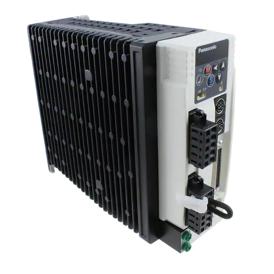
Page 20: Parts Description
Parts Description Driver • A and B-frame Mode switching button Set button MODE Display LED (6-digit) Rotary switch (ID) Data setup button Torque monitor check pin (IM) : SHIFT : UP Velocity monitor check pin (SP) : DOWN Check pin (G : GND) Connector Communication Main power... - Page 21 [Before Using the Products] Set button • E and F-frame Rotary switch (ID) Mode switching button MODE Torque monitor check pin (IM) Display LED (6-digit) Velocity monitor check pin (SP) Data setup button : SHIFT Main power : UP input terminals : DOWN (L1,L2,L3) Check pin (G : GND)
-
Page 22: Motor
Parts Description Motor • MSMD 50W to 750W • MAMA 100W to 750W • MQMA 100W to 400W Encoder cable Motor cable Rotary encoder Connector for brake cable (Only applicable to the motor Motor frame with electromagnetic brake) Flange Mounting holes (X4) e.g.) : Low inertia type (MSMD series, 50W) Connector for motor and brake •... -
Page 23: Console
[Before Using the Products] Console Main Body Connector Console body Display (7-segment LED) Cable Touch panel <Note> Console is an option (Part No.: DV0P4420). Display/Touch panel Display LED (6 digits) Displays ID number of selected driver (in 2 digits). The value set in Pr00 (Address) is ID No. Displays the parameter No. -
Page 24: Installation
How to Install Install the driver and the motor properly to avoid a breakdown or an accident. Driver Installation Place 1) Indoors, where the products are not subjected to rain or direct sun beams. The products are not water- proof. 2) Where the products are not subjected to corrosive atmospheres such as hydrogen sulfide, sulfurous acid, chlorine, ammonia, chloric gas, sulfuric gas, acid, alkaline and salt and so on, and are free from splash of inflammable gas, grinding oil, oil mist, iron powder or chips and etc. - Page 25 [Before Using the Products] Mounting Direction and Spacing • Reserve enough surrounding space for effective cooling. • Install fans to provide uniform distribution of temperature in the control panel. • Observe the environmental conditions of the control panel described in the next page. 100mm or more 40mm...
-
Page 26: Motor
How to Install Motor Installation Place Since the conditions of location affect a lot to the motor life, select a place which meets the conditions below. 1) Indoors, where the products are not subjected to rain or direct sun beam. The products are not water- proof. - Page 27 [Before Using the Products] Stress to Cables 1) Avoid a stress application to the cable outlet and connecting portion by bending or self-weight. 2) Especially in an application where the motor itself travels, fix the attached cable and contain the extension junction cable into the bearer so that the stress by bending can be minimized.
-
Page 28: Console
How to Install Console Installation Place 1) Indoors, where the products are not subjected to rain or direct sun beam. The products are not water- proof. 2) Where the products are not subjected to corrosive atmospheres such as hydrogen sulfide, sulfurous acid, chlorine, ammonia, chloric gas, sulfuric gas, acid, alkaline and salt and so on, and are free from splash of inflammable gas, grinding oil, oil mist, iron powder or chips and etc. -
Page 29: Preparation
[Preparation] page System Configuration and Wiring ......28 Overall Wiring (Connecting Example of C-frame, 3-phase) ..28 Overall Wiring (Connecting Example of E-frame) ....... 30 Driver and List of Peripheral Equipments........32 Wiring of the Main Circuit (A to D-frame) ........34 Wiring of the Main Circuit (E and F-frame)........ -
Page 30: System Configuration And Wiring
System Configuration and Wiring Overall Wiring (Connecting Example of C-frame, 3-phase) • Wiring of the Main Circuit (see P.32, 33 and 309.) Circuit Breaker (NFB) Use the circuit breaker matching capacity of the power source to protect the power lines. (see P.309) Noise Filter (NF) Prevents external noise from the power... - Page 31 [Preparation] PC (to be supplied by customer) Setup support software "PANATERM " ® DV0P4460 (English, Japanese version/option) Console (option) DV0P4420 • Wiring to Connector, CN X3/X4 (option) (Connection to PC or host controller) • Wiring to Connector, CN X5 (Connection to host controller) Junction cable for encoder •...
-
Page 32: Overall Wiring (Connecting Example Of E-Frame)
System Configuration and Wiring Overall Wiring (Connecting Example of E-frame) • Wiring of the Main Circuit (see P.32, 33 and 309.) Circuit Breaker (NFB) Use the circuit breaker matching capacity of the power source to protect the power lines. (see P.309) Noise Filter (NF) Prevents external noise from the power lines. - Page 33 [Preparation] PC (to be supplied by customer) Setup support software "PANATERM " ® DV0P4460 (English, Japanese version/option) Console (option) DV0P4420 • Wiring to Connector, CN X3/X4 (option) (Connection to PC or host controller) • Wiring to Connector, CN X5 (Connection to host controller) •...
-
Page 34: Driver And List Of Peripheral Equipments
System Configuration and Wiring Driver and List of Applicable Peripheral Equipments Cable Cable Circuit Required Applicable Rated Noise Surge Magnetic Noise filter Power breaker diameter diameter Driver Voltage Connection (at the rated (rated motor output filter absorber for signal contactor (main circuit) (control circuit) load) - Page 35 [Preparation] Cable Cable Required Circuit Applicable Rated Noise Surge Noise filter Magnetic Power breaker diameter diameter Driver Voltage Connection (at the rated (rated motor output filter contactor absorber for signal (main circuit) (control circuit) load) current) approx. MGMA 2.0kW 3.8kVA MDMA BMF6352N MHMA...
-
Page 36: Wiring Of The Main Circuit (A To D-Frame)
System Configuration and Wiring Wiring of the Main Circuit (A to D-frame) • Wiring should be performed by a specialist or an authorized personnel. • Do not turn on the power until the wiring is completed. Tips on Wiring 8 to 9mm 1) Peel off the insulation cover of the cable. -
Page 37: Wiring Of The Main Circuit (E And F-Frame)
[Preparation] Wiring of the Main Circuit (E and F-frame) • Wiring should be performed by a specialist or an authorized personnel. • Do not turn on the power until the wiring is completed. Tips on Wiring 1) Take off the cover fixing screws, and detach the terminal cover. 2) Make wiring Use clamp type terminals of round shape with insulation cover for wiring to the terminal block. - Page 38 System Configuration and Wiring Wiring Diagram Compose the circuit so that the main circuit power will be shut off when an error occurs. In Case of Single Phase, 100V (A and B-frame) In Case of Single Phase, 200V (A and B-frame) +10% +10% +10%...
- Page 39 [Preparation] [Motor portion] In Case of 3-Phase, 200V (E and F-frame) Connector : by Japan Aviation Electronics Ind. +10% +10% Power supply 3-phase, 200V to 230V –15% –15% Built-in thermostat of an external regenerative resistor (light yellow) JL04V-2E20-4PE-B-R ON OFF JL04HV-2E22-22PE-B-R PIN No.
-
Page 40: Wiring To The Connector, Cn X6 (Connection To Encoder)
System Configuration and Wiring Wiring to the Connector, CN X6 (Connection to Encoder) Tips on Wiring Maximum cable length between the driver and the motor to be 20m. Power Consult with a dealer or distributor if you want to use the longer supply cable than 20m. - Page 41 [Preparation] • MSMA 1kW to 5kW Pin No. of connector • MDMA 1kW to 5kW CN X6 • MHMA 500W to 5kW Regulator • MFMA 400W to 4.5kW • MGMA 900W to 4.5kW Straight plug N/MS3106B20-29S Case Cable clamp N/MS3057-12A Twisted pair (by Japan Aviation Electronics Ind.) motor...
-
Page 42: Wiring To The Connector, Cn X3 And 4 (Connection To Pc, Host Controller Or Console)
System Configuration and Wiring Wiring to the Connectors, CN X3 and X4 (Connection to PC, Host or Console) • This servo driver features 2 kinds of communication function, RS232 and RS485, and you can use in 3 connecting methods. In Case of Communication with One Driver Using RS232 By connecting the PC and the driver via RS232, you can utilize the setup support software, "PANATERM ®... -
Page 43: Wiring To The Connector, Cn X5 (Connection To Host Controller)
[Preparation] Wiring to the Connector, CN X5 (Connection to Host Controller) • Tips on wiring Peripheral apparatus such as host controller should be located or shorter within 3m . Controller 30cm or longer Separate the main circuit at least 30cm away. Power supply Don't pass them in the same duct, nor bind them together. -
Page 44: Timing Chart
Timing Chart Timing Chart Control power supply (L1C,L2C) approx.100 to 300 ms Internal control established power supply approx.2s approx.1.5s Action of reset (initialization) usually operation driver CPU 0s or longer Main power supply (L1,L2,L3) 10ms or longer S-RDY output (X5, Pin-34 and 35) 10ms or longer 0ms or longer... - Page 45 [Preparation] When an Error (Alarm) Has Occurred (at Servo-ON Command) Alarm alarm normal Dynamic brake engaged *2 energized 0.5 to 5 ms non-energized Motor energization Servo-Ready output not ready ready (S-RDY) Servo-Alarm output alarm not alarm (ALM) Setup value of Break release output Pr6B released (ON)
- Page 46 Timing Chart Servo-ON/OFF Action While the Motor Is at Stall (Servo-Lock) Servo-ON input (SEV-ON) approx.2ms 1 to 5ms engaged *3 released engaged *2 Dynamic brake t1 *1 Motor energization not-energized energized not-energized approx.40ms approx.2ms Brake release output engaged (OFF) released (ON) engaged (OFF) (BRK-OFF) <Cautions>...
- Page 47 [Preparation] Servo-ON/OFF Action While the Motor Is in Motion (Timing at emergency stop or trip. Do not repeat this sequence. During the normal operation, stop the motor, then make Servo-ON/OFF action.) at Servo-ON at Servo-OFF Servo-ON input (SEV-ON) 1 to 5ms Dynamic brake engaged *3 released...
-
Page 48: Built-In Holding Brake
Built-in Holding Brake In the applications where the motor drives the vertical axis, this brake would be used to hold and prevent the work (moving load) from falling by gravity while the power to the servo is shut off. <Caution> Use this built-in brake for "Holding"... - Page 49 [Preparation] Specifications of Built-in Holding Brake Static friction Rotor inertia Engaging Releasing Exciting Permissible Permissible Motor Motor Releasing torque –4 time time current DC A work (J) per total work series output voltage (at cool-off) one braking x 10 • •...
-
Page 50: Dynamic Brake
Dynamic Brake This driver is equipped with a dynamic brake for emergency stop. Pay a special attention to the followings. <Caution> 1. Dynamic brake is only for emergency stop. Do not start/stop the motor by turning on/off the Servo-ON signal (SRV-ON). Or it may damage the dynamic brake circuit of the driver. - Page 51 [Preparation] 2) Setup of driving condition from deceleration to after stop by Servo-OFF (Pr69) Contents of Driving condition Sequence at main deviation Servo-OFF (Pr69) During deceleration after stalling counter Setup value of Pr69 Clear Free-run Clear Free-run Clear Free-run Free-run Clear Hold Free-run...
-
Page 52: Caution On Homing
Caution on Homing Operation • In homing action by using the host controller, stop position might not be stabilized if the origin input (Z- phase of the encoder) is entered while the motor is not decelerated enough after the proximity input is turned on. -
Page 53: Setup Of Parameter And Mode
Setup of Parameter and Mode [Preparation] Outline of Parameter This driver is equipped with various parameters to set up its characteristics and functions. This section describes the function and purpose of each parameter. Read and comprehend very well so that you can adjust this driver in optimum condition for your running requirements. -
Page 54: Composition And List Of Parameters
Setup of Parameter and Mode Composition and List of Parameters Parameter No. Group Outline Functional selection 00 to 0F You can select a control mode, designate I/O signals and set up a baud rate. Adjustment 10 to 1F, You can set up servo gains (1st and 2nd) of position, velocity, 27 to 2E integration, etc, and time constants of various filters. - Page 55 [Preparation] Parameters for Functional Selection Parameter No. Set up of parameter Range Default Unit Related Control Mode 00 *1 Address of axis 0 to 15 – 01 *1 Initial display of LED 0 to 17 – 02 *1 Setup of control mode 0 to 6 –...
- Page 56 Setup of Parameter and Mode Parameters for Auto-Gain Tuning Default Parameter No. Set up of parameter Range Unit Related Control Mode A to C-frame D to F-frame Inertia ratio 0 to 10000 <250> Setup of real-time auto-gain tuning mode 0 to 7 –...
- Page 57 [Preparation] Parameters for Position Control Parameter No. Set up of parameter Range Default Unit Related Control Mode 40*1 Selection of command pulse input 0 to 1 – P, F 41*1 setup of rotational direction of command pulse 0 to 1 –...
- Page 58 Setup of Parameter and Mode Parameters for Sequence Parameter No. Set up of parameter Range Default Unit Related Control Mode In-position (positioning complete) range 0 to 32767 Pulse P, F Zero speed 10 to 20000 r/min At-speed (arrived speed) 10 to 20000 1000 r/min S, T...
-
Page 59: Setup Of Torque Limit
[Preparation] Setup of Torque Limit Torque limit setup range is 0 to 300 and default is 300 except the combinations of the motor and the driver listed in the table below. Max. value of Max. value of Frame Model No. Applicable motor Frame Model No. -
Page 60: How To Use The Front Panel And Console
How to Use the Front Panel and Console Setup with the Front Panel Composition of Touch Panel and Display Display LED (6-digit) All of LED will flash when error occurs, and switch to error display screen. All of LED will flash slowly when warning occurs. Shifting of the digit for data changing to higher digit. -
Page 61: Initial Status Of The Front Panel Display(7 Segment Led)
[Preparation] Initial Status of the Front Panel Display (7 Segment LED) Front panel display shows the following after turning on the power of the driver. approx. 2 sec approx. 0.6 sec approx. 0.6 sec Initial display of LED (Determined by the setup of Parameter, Pr01 "Initial status of LED".) Initial Status of the Console Display (7 Segment LED) Turn on the power of the driver while inserting the console connector to the driver main body, or inserting the... -
Page 62: Structure Of Each Mode
How to Use the Front Panel and Console Structure of Each Mode Use each button on the touch panel to select the structure and switch the mode. SELECTION display Monitor mode (SET button) Initial status of the Console LED (Mode switching button) <Note>... - Page 63 [Preparation] EXECUTION display ..P.63 (SET button) ..P.69 • For details of parameters, refer to (SET button) "Parameter setup" of each mode..P.70 (SET button) ..P.71 (SET button) ..P.73 • Alarm clear ..P.74 • Auto-offset adjustment (front panel only) ..P.77 • Clear of absolute encoder (SET button) ..P.75 •...
- Page 64 How to Use the Front Panel and Console How to Set 1) Insert the console connector to CN X6 of the driver, and turn on the power of the driver. Parameter setup 2) Press 3) Press 4) Select the required parameters with 5) Press 6) Change the value with...
-
Page 65: Monitor Mode
[Preparation] Monitor Mode When you turn on the Product for the first time, display shows . (at motor stall) To change this display, change the setup of Pr01 (Initial status of LED). (For details, refer to Parameter Setup of each control mode.) SELECTION display EXECUTION display Display... - Page 66 How to Use the Front Panel and Console Display of Position Deviation, Motor Rotational Speed and Torque Output Data ..Positional deviation (cumulative pulse counts of deviation counter) • – display : generates rotational torque of CW direction (viewed from shaft end) no display : generates rotational torque of CCW direction (viewed from shaft end) ..Rotational speed of the motor unit [r/min] •...
- Page 67 [Preparation] • Signal No. and its title Input signal Input signal Signal Signal Title Symbol Pin No. Title Symbol Pin No. Servo-ON SRV-ON Servo-Ready S-RDY 35/34 Alarm clear A-CLR Servo-Alarm 37/36 CW over-travel inhibit Positioning complete (In-position) COIN 39/38 CCW over-travel inhibit CCWL Release of external brake BRK-OFF...
- Page 68 How to Use the Front Panel and Console Software Version Displays the software version of the driver. Alarm Display ..no alarm ..Alarm occurrence • Over-regeneration alarm : Turns on when regenerative load reaches more than 85% of alarm trigger level of regenerative load protection. Alarm trigger level is defined as 10% of regenerative resister working ratio, when Pr6C "Selection of external regenerative resister "...
- Page 69 [Preparation] External Scale Deviation • Polarity (+) : CCW, (-) : CW Limited by ± 999999. Note) You can 0-clear the external scale deviation during normal auto-gain tuning and motor trial run. Automatic Motor Recognizing Function Automatic recognition is valid. Display of Analog Input Value (Front Panel Only) Input voltage value [V] Input signal...
- Page 70 How to Use the Front Panel and Console Display of the Factor of No-Motor Running Displays the factor of no-motor running in number..Position control ..Torque control ..Velocity control ..Full-closed control Factor No. Control mode • Explanation of factor No. Factor Control Factor...
-
Page 71: Parameter Setup Mode
[Preparation] Parameter Setup Mode Operation at SELECTION display Press once after pressing from initial status of LED to change the display to Parameter setup mode, Parameter No. (Hexadecimal No.) <Note> For parameters which place is displayed with “ ”, the content changed and written to EEPROM becomes valid after turning off the power once. -
Page 72: Eeprom Writing Mode
How to Use the Front Panel and Console EEPROM Writing Mode EEPROM Writing Operation at SELECTION display Starting from the initial LED status, press two time after pressing then brings the display of EEPROM Writing Mode, Operation at EXECUTION display Press to make EXECUTION DISPLAY to... -
Page 73: Auto-Gain Tuning Mode
[Preparation] Auto-Gain Tuning Mode Normal Mode Auto-Gain Tuning Screen <Remarks> • For details of normal auto-gain tuning, refer to P.236, "Normal Auto-Gain Tuning" of Adjustment. Pay a special attention to applicable range and cautions. • The motor will be driven in a preset pattern by the driver in normal auto-gain tuning mode. You can change this pattern with Pr25 (Setup of action at normal auto-gain tuning), however, shift the load to where the operation in this pattern may not cause any trouble, then execute this tuning. - Page 74 How to Use the Front Panel and Console Fit-Gain Screen Operation at SELECTION display Operation at EXECUTION display Press to call for EXECUTION DISPLAY. You can change/store the setup of real time auto-gain tuning/adaptive filter or start the fit-gain function by using key, after matching the ( 6 ) ( 5 ) ( 4 ) ( 3 ) ( 2 ) ( 1 ) decimal point to (1), (2), (4), (6) by pressing...
-
Page 75: Auxiliary Function Mode
[Preparation] Auxiliary Function Mode Alarm Clear Screen Protective function will be activated and release the motor stall status (error status). Operation at SELECTION display Starting from the initial LED status, Press four time after pressing then press to make a display to Operation at EXECUTION display Press to call for... - Page 76 How to Use the Front Panel and Console Automatic Offset Adjustment (Front Panel Only) Automatically adjust the offset value of Pr52 (Velocity command offset) of analog velocity command input (SPR/TRQR). Operation at SELECTION display Operation at EXECUTION display • Press to call for EXECUTION display of When you execute automatic offset adjustment, make command input to 0V, then keep pressing...
- Page 77 [Preparation] Trial Run (JOG Run) You can make a trial run (JOG run) without connecting the Connector, CN X5 to the host controller such as PLC. <Remarks> • Separate the motor from the load, detach the Connector, CN X5 before the trial run. •...
- Page 78 How to Use the Front Panel and Console Procedure for Trial Run When you use the console, insert the console connector to CN X4 of the driver securely and turn on the driver power. Operation at SELECTION display Press four time after pressing to setup auxiliary function mode, then with , make a display to...
- Page 79 [Preparation] Clearing of Absolute Encoder Only applicable to the system which uses absolute encoder. You can clear the alarm and multi-turn data of the absolute encoder. Operation at SELECTION display Press four time after pressing , to setup auxiliary function mode, then with , make a display to Operation at EXECUTION display...
- Page 80 How to Use the Front Panel and Console Clearing of External Scale Error (Front panel only) You can clear an error of the external scale. Operation at SELECTION display Press four time after pressing , to setup auxiliary function mode, then with , make a display to Operation at EXECUTION display...
-
Page 81: Copying Function (Console Only)
[Preparation] Copying Function (Console Only) Copying of Parameters from the Driver to the Console Operation at SELECTION display Starting from initial LED status, Press five time after pressing then press , to make a display to Operation at EXECUTION display Press to call for EXECUTION DISPLAY of... - Page 82 How to Use the Front Panel and Console Copying of Parameters from the Console to the Driver Operation at SELECTION display Starting from initial LED status, Press five time after pressing , then press to make a display to Operation at EXECUTION display Press to call for EXECUTION DISPLAY of...
-
Page 83: Connection And Setup Of Position Control Mode
[Connection and Setup of Position Control Mode] page Control Block Diagram of Position Control Mode 82 Wiring to the Connector, CN X5 ......83 Wiring Example to the Connector, CN X5 ........83 Interface Circuit ................84 Input Signal and Pin No. of the Connector, CN X5 ..... 86 Output Signal and Pin No. -
Page 84: Control Block Diagram Of Position Control Mode
Control Block Diagram of Position Control Mode... -
Page 85: Wiring To The Connector, Cn X5
Wiring to the Connector, CN X5 [Connection and Setup of Position Control Mode] Wiring Example to the Connector, CN X5 Wiring Example of Position Control Mode... -
Page 86: Interface Circuit
Wiring to the Connector, CN X5 Interface Circuit Input Circuit Connection to sequence input signals • Connect to contacts of switches and relays, or open collector output transistors. • When you use contact inputs, use the switches and relays for micro current to avoid contact failure. •... - Page 87 [Connection and Setup of Position Control Mode] Output Circuit SO1 SO2 Sequence output circuit Install toward the direction as the fig. shows without fail. • The output circuit is composed of open collector transistor outputs in the Darlington connection, and connect to relays or ALM+ etc.
-
Page 88: Input Signal And Pin No. Of The Connector, Cn X5
Wiring to the Connector, CN X5 Input Signal and Pin No. of the Connector, CN X5 Input Signals (common) and Their Functions Title of signal Function I/F circuit Pin No. Symbol Power supply for COM+ • Connect + of the external DC power supply (12 to 24V). –... - Page 89 [Connection and Setup of Position Control Mode] Title of signal Pin No. Symbol Function I/F circuit Electronic gear • Function varies depending on the control mode. (division/ • You can switch the numerator of electronic gear. P.84 multiplication) • By connecting to COM–, you can switch the numerator of switching input Position/ electronic gear from Pr48 (1st numerator of electronic...
- Page 90 Wiring to the Connector, CN X5 Title of signal Pin No. Symbol Function I/F circuit Deviation • Function varies depending on the control mode. counter clear P.84 • Input (CL) which clears the positional deviation counter input and full-closed deviation counter. •...
- Page 91 [Connection and Setup of Position Control Mode] Input Signals (Pulse Train) and Their Functions You can select appropriate interface out of two kinds, depending on the command pulse specifications. • Pulse train interface exclusive for line driver Title of signal Pin No. Symbol Function I/F circuit...
- Page 92 Wiring to the Connector, CN X5 Input Signals (Analog Command) and Their Functions Title of signal Pin No. Symbol Function I/F circuit • Function varies depending on control mode. Speed command input Pr02 Control mode Function P.84 • Input of external speed command (SPR) when the velocity control is selected.
- Page 93 [Connection and Setup of Position Control Mode] Title of signal Pin No. Symbol Function I/F circuit CCW-Torque CCWTL • Function varies depending on Pr02 (Control mode setup). limit input Pr02 Control mode Function P.84 • Function varies depending on Pr5B (Selection of torque command) Pr5B Content...
-
Page 94: Output Signal And Pin No. Of The Connector, Cn X5
Wiring to the Connector, CN X5 Output signal and Pin No. of the Connector, CN X5 Output Signals (Common) and Their Functions I/F circuit Title of signal Pin No Symbol Function • Feeds out the timing signal which activates the electromagnetic brake of the motor. External brake BRKOFF+ •... - Page 95 [Connection and Setup of Position Control Mode] Output Signals (Pulse Train) and Their Functions Title of signal Pin No Symbol Function I/F circuit • Feeds out the divided encoder signal or external scale signal (A, B, Z- A-phase output OA + phase) in differential.
- Page 96 Wiring to the Connector, CN X5 Output Signals (Analog) and Their Functions Title of signal Pin No Symbol Function I/F circuit • The content of output signal varies depending on Pr08 (Torque monitor Torque monitor (IM) selection). signal output P.85 •...
- Page 97 [Connection and Setup of Position Control Mode] Output Signals (Others) and Their Functions Title of signal Pin No Symbol Function I/F circuit – • Signal ground Signal ground 13,15, • This output is insulated from the control signal power (COM–) inside of the 17,25 driver.
-
Page 98: Connecting Example To Host Controller
Wiring to the Connector, CN X5 Connecting Example to Host Controller Matsushita Electric Works, FPG-C32T Driver FPG-C32T(FP∑) A4-series 2kΩ PULS1 pulse 220Ω command pulse command PULS2 input output 2kΩ SIGN1 pulse command 220Ω pulse command SIGN2 input output 5.6kΩ Origin input Z-phase output COM+... - Page 99 [Connection and Setup of Position Control Mode] Matsushita Electric Works, FP2-PP2 AFP2430 Driver A4-series FP2-PP2 AFP2430 PULS1 pulse pulse command command 220Ω PULS2 input output SIGN1 pulse pulse command command 220Ω SIGN2 input output 220Ω Z-phase Origin input output OZ– COM+ 4.7kΩ...
- Page 100 Wiring to the Connector, CN X5 Yokogawa Electric , F3NC11-ON Driver A4-series F3NC11-0N PULS1 pulse 220Ω pulse command command PULS2 output input SIGN1 pulse 220Ω pulse command SIGN2 command output input 1kΩ Origin line driver Z-phase input output OZ– 3.5kΩ COM+ Emergency stop 4.7kΩ...
- Page 101 [Connection and Setup of Position Control Mode] Yokogawa Electric , F3YP14-0N/F3YP18-0N Driver A4-series F3YP14-0N/F3YP18-0N PULS1 pulse pulse command command 220Ω PULS2 input output SIGN1 pulse pulse command command 220Ω SIGN2 output input 240Ω Z-phase Origin line driver output input OZ– COM+ 4.7kΩ...
- Page 102 Wiring to the Connector, CN X5 Omron, CS1W-NC113 Driver A4-series CS1W-NC113 1.6kΩ PULS1 pulse pulse command command 220Ω output PULS2 input 1.6kΩ SIGN1 pulse pulse command command 220Ω output SIGN2 input 150Ω Origin line driver Z-phase input output OZ– Power supply for output COM+ 4.7kΩ...
- Page 103 [Connection and Setup of Position Control Mode] Omron, CS1W-NC133 Driver CS1W-NC133 A4-series PULS1 pulse 220Ω command pulse command PULS2 input output SIGN1 pulse 220Ω command pulse command SIGN2 input output 150Ω Z-phase Origin line driver output input OZ– power supply COM+ for output 4.7kΩ...
- Page 104 Wiring to the Connector, CN X5 Omron, C200H-NC211 Driver A4-series C200H-NC211 1.6kΩ PULS1 Pulse (CW+CCW) pulse 220Ω command output PULS2 input 1.6kΩ SIGN1 Directional output pulse 220Ω command SIGN2 input 150Ω Origin line driver Z-phase input output OZ– Power supply for output COM+ 4.7kΩ...
- Page 105 [Connection and Setup of Position Control Mode] Mitsubishi, A1SD75/AD75P1 Driver A1SD75/AD75P1 A4-series PULS1 pulse 220Ω command pulse command PULS2 input output SIGN1 pulse 220Ω command pulse command SIGN2 input output 500Ω Z-phase Zero point signal output OZ– COM+ 4.7kΩ Counter clear input Deviation counter 4.7kΩ...
-
Page 106: Trial Run (Jog Run) At Position Control Mode
Trial Run (JOG run) at Position Control Mode Inspection Before Trial Run Display LED (1) Wiring inspection • Miswiring (Especially power input/motor output) • Short/Earth • Loose connection Power supply (2) Check of power/voltage • Rated voltage (3) Fixing of the motor CN X6 •... - Page 107 [Connection and Setup of Position Control Mode] Setup of Motor Rotational Speed and Input Pulse Frequency Pr4A Pr48 x 2 Input pulse Motor Pr4B frequency rotational (pps) speed (r/min) 17-bit 2500P/r 1 x 2 2500 3000 10000 10000 1 x 2 10000 500K 3000...
-
Page 108: Real-Time Auto-Gain Tuning
Real-Time Auto-Gain Tuning Auto-gain Auto-filter Torque Motor Outline Position/Velocity setup adjustment command current command Position/Velocity Adaptive Current Motor control Filter control The driver estimates the load inertia of the ma- Action command under actual condition chine in real time, and automatically sets up the Resonance frequency calculation optimum gain responding to the result. -
Page 109: Adaptive Filter
[Connection and Setup of Position Control Mode] Adaptive Filters The adaptive filter is validated by setting up Pr23 (Setup of adaptive filter mode) to other than 0. The adaptive filter automatically estimates a resonance frequency out of vibration component presented in the motor speed in motion, then removes the resonance components from the torque command by setting up the notch filter coefficient automatically, hence reduces the resonance vibration. -
Page 110: Parameter Setup
Parameter Setup Parameters for Functional Selection Standard default : < > Setup PrNo. Title Function/Content range Address 0 to 15 In the communication with the host via RS232/485 for multi-axes application, it is <1> necessary to identify which axis the host is communicating. Use this parameter to confirm the address of the axis in numbers. - Page 111 [Connection and Setup of Position Control Mode] Standard default : < > Setup PrNo. Title Function/Content range Selection of 0 to 3 You can set up the torque limiting method for CCW/CW direction. torque limit <1> Setup value X5 CCWTL : Pin-16 X5 CWTL : Pin-18 <1>...
- Page 112 Parameter Setup Standard default : < > Setup PrNo. Title Function/Content range Selection of torque 0 to 12 You can set up the content of the analog torque monitor of the signal output (IM : CN X5, Pin- monitor (IM) <0>...
-
Page 113: Parameters For Adjustment Of Time Constant Of Gains And Filters
[Connection and Setup of Position Control Mode] Standard default : < > Setup PrNo. Title Function/Content range Baud rate setup of 0 to 5 You can set up the communication speed of RS485. • Error of baud rate is ±0.5%. RS485 <2>... -
Page 114: Parameters For Auto-Gain Tuning
Parameter Setup Standard default : < > Setup PrNo. Title Unit Function/Content range 2nd gain of 0 to 3000 Position loop, velocity loop, speed detection filter and torque command position loop A to C-frame:<73>* filter have their 2 pairs of gain or time constant (1st and 2nd). D to F-frame:<38>* For details of switching the 1st and the 2nd gain or the time constant, refer 2nd gain of velocity... - Page 115 [Connection and Setup of Position Control Mode] Standard default : < > Setup PrNo. Title Unit Function/Content range You can set up the machine stiffness in 16 steps while the real-time auto- Selection of 0 to 15 – gain tuning is valid. machine stiffness A to C-frame: at real-time...
- Page 116 Parameter Setup Standard default : < > Setup PrNo. Title Unit Function/Content range 2nd notch 100 to 1500 You can set up the 2nd notch width of the resonance suppressing filter in frequency <1500> 5 steps. The notch filter function is invalidated by setting up this parame- ter to "1500".
-
Page 117: Parameters For Adjustment (2Nd Gain Switching Function)
[Connection and Setup of Position Control Mode] Parameters for Adjustment (2nd Gain Switching Function) Standard default : < > Setup PrNo. Title Unit Function/Content range Setup of 2nd gain 0 to 1 – You can select the PI/P action switching of the velocity control or 1st/2nd gain switching. <1>* Setup value Gain selection/switching... -
Page 118: Parameters For Position Control
Parameter Setup Standard default : < > Setup PrNo. Title Unit Function/Content range Switching time of 0 – 10000 (setup You can setup the 166µs e.g.) position gain <20>* value +1) step-by-step switching Kp1(Pr10)>Kp2(Pr18) x 166µs time to the position Kp1(Pr10) bold line Pr35=... - Page 119 [Connection and Setup of Position Control Mode] Standard default : < > Setup PrNo. Title Function/Content range Invalidation of 0 to 1 You can select either the validation or the invalidation of the command pulse inhibit command pulse <1> input (INH : CN X5 Pin-33). inhibit input Setup value INH input...
- Page 120 Parameter Setup Standard default : < > Setup PrNo. Title Function/Content range Reversal of pulse 0 to 3 You can set up the B-phase logic and the output source of the pulse output (X5 OB+ output logic <0> : Pin-48, OB– : Pin-49). With this parameter, you can reverse the phase relation between the A-phase pulse and the B-phase pulse by reversing the B-phase logic.
- Page 121 [Connection and Setup of Position Control Mode] Standard default : < > Setup PrNo. Title Function/Content range Electronic gear function-related (Pr48-4B) (continued from the previous page) <Setup example when numerator ≠0> 1st numerator of • When division/multiplication ratio=1, it is essential to keep the relationship in which electronic gear the motor turns one revolution with the command input (f) of the encoder resolution.
-
Page 122: Parameters For Velocity/Torque Control
Parameter Setup Parameters for Velocity and Torque Control Standard default : < > Setup PrNo. Title Unit Function/Content range You can set up the limit value of the motor output torque (Pr5E : 1st 1st torque limit 0 to 500 torque, Pr5F : 2nd torque). - Page 123 [Connection and Setup of Position Control Mode] Standard default : < > Setup PrNo. Title Unit Function/Content range You can set up the timing to feed out the zero-speed detection output signal Zero-speed 10 to r/min (ZSP : CN X5, Pin-12 or TCL : CN X5, Pin-40) in rotational speed [r/min]. 20000 The zero-speed detection signal (ZSP) will be fed out when the motor <50>...
- Page 124 Parameter Setup Standard default : < > Setup PrNo. Title Unit Function/Content range Sequence at main 0 to 9 – When Pr65 (LV trip selection at main power OFF) is 0, you can set up, 1) the action during deceleration and after stalling power OFF <0>...
- Page 125 [Connection and Setup of Position Control Mode] Standard default : < > Setup PrNo. Title Unit Function/Content range Setup of 0 to 100 You can set up the time from when the brake release signal (BRK-OFF : CN X5, Pin-10 and 11) turns off to when the motor is de-energized mechanical brake <0>...
- Page 126 Parameter Setup Standard default : < > Setup PrNo. Title Unit Function/Content range Detection time of 35 to 1000 You can set up the time to detect the shutoff while the main power is kept main power off <35> shut off continuously. The main power off detection is invalid when you set up this to 1000.
-
Page 127: Connection And Setup Of Velocity Control Mode
[Connection and Setup of Velocity Control Mode] page Control Block Diagram of Velocity Control Mode ..126 Wiring to the Connector, CN X5 ......127 Wiring Example to the Connector, CN X5 ......... 127 Interface Circuit ................. 128 Input Signal and Pin No. of the Connector, CN X5 ....130 Output Signal and Pin No. -
Page 128: Control Block Diagram Of Velocity Control Mode
Control block diagram of velocity control mode... -
Page 129: Wiring To The Connector, Cn X5
Wiring to the connector, CN X5 [Connection and setup of velocity control mode] Wiring Example to the Connector CN X5 Wiring Example of Velocity Control Mode... -
Page 130: Interface Circuit
Wiring to the connector, CN X5 Interface Circuit Input Circuit Connection to sequence input signals 12 to 24V 7 COM+4.7kΩ • Connect to contacts of switches and relays, or open collector output transistors. SRV-ON etc. • When you use contact inputs, use the switches and relays for Relay micro current to avoid contact failure. - Page 131 [Connection and setup of velocity control mode] Output Circuit SO1 SO2 Sequence output circuit Install toward the direction as the fig. shows without fail. • The output circuit is composed of open collector transistor outputs in the Darlington connection, and connect to relays or ALM+ etc.
-
Page 132: Input Signal And Pin No. Of The Connector, Cn X5
Wiring to the connector, CN X5 Input Signal and Pin No. of the Connector, CN X5 Input Signals (common) and Their Functions Title of signal Function I/F circuit Pin No. Symbol Power supply for COM+ • Connect + of the external DC power supply (12 to 24V). –... - Page 133 [Connection and setup of velocity control mode] Title of signal Pin No. Symbol Function I/F circuit Internal • Function varies depending on the control mode. INTSPD3 command speed • You can switch the numerator of electronic gear. P.128 selection 3 input •...
- Page 134 Wiring to the connector, CN X5 Title of signal Pin No. Symbol Function I/F circuit Selection 2 input INTSPD2 • Function varies depending on the control mode. of internal • Input (CL) which clears the positional deviation counter P.128 command speed and full-closed deviation counter.
- Page 135 [Connection and setup of velocity control mode] Input Signals (Analog Command) and Their Functions Title of signal Pin No. Symbol Function I/F circuit • Function varies depending on control mode. Speed command input Pr02 Control mode Function P.128 • Input of external speed command (SPR) when the Velocity velocity control is selected.
- Page 136 Wiring to the connector, CN X5 Title of signal Pin No. Symbol Function I/F circuit CCW-Torque limit CCWTL • Function varies depending on Pr02 (Control mode setup). input Pr02 Control mode Function P.128 • Function varies depending on Pr5B (Selection of torque command) Pr5B Content...
-
Page 137: Output Signal And Pin No. Of The Connector, Cn X5
[Connection and setup of velocity control mode] Output signal and Pin No. of the Connector, CN X5 Output Signals (Common) and Their Functions I/F circuit Title of signal Pin No Symbol Function • Feeds out the timing signal which activates the electromagnetic brake of the motor. External brake BRKOFF+ •... - Page 138 Wiring to the connector, CN X5 Output Signals (Pulse Train) and Their Functions Title of signal Pin No Symbol Function I/F circuit • Feeds out the divided encoder signal or external scale signal (A, B, Z- A-phase output OA + phase) in differential.
- Page 139 [Connection and setup of velocity control mode] Output Signals (Analog) and Their Functions Title of signal Pin No Symbol Function I/F circuit • The content of output signal varies depending on Pr08 (Torque monitor Torque monitor (IM) selection). signal output P.129 •...
-
Page 140: Trial Run (Jog Run) At Velocity Control Mode
Trial Run (JOG run) at Velocity Control Mode Inspection Before Trial Run Display LED (1) Wiring inspection • Miswiring (Especially power input/motor output) • Short/Earth • Loose connection Power supply (2) Check of power/voltage • Rated voltage (3) Fixing of the motor CN X6 •... -
Page 141: Trial Run By Connecting The Connector, Cn X5
[Connection and setup of velocity control mode] Trial Run by Connecting the Connector, CN X5 1) Connect the CN X5. 2) Enter the power (DC12-24V) to control signal (COM+, COM–) 3) Enter the power to the driver. 4) Confirm the default values of parameters. 5) Connect the Servo-ON input (SRV-ON, CN X5, Pin-29) and COM–... -
Page 142: Real-Time Auto-Gain Tuning
Real-Time Auto-Gain Tuning Auto-gain Auto-filter Torque Outline Motor Position/Velocity setup adjustment command current command Adaptive Current Position/Velocity Motor control Filter control The driver estimates the load inertia of the ma- Action command under actual condition chine in real time, and automatically sets up the Resonance frequency calculation optimum gain responding to the result. -
Page 143: Adaptive Filter
[Connection and setup of velocity control mode] Adaptive Filters The adaptive filter is validated by setting up Pr23 (Setup of adaptive filter mode) to other than 0. The adaptive filter automatically estimates a resonance frequency out of vibration component presented in the motor speed in motion, then removes the resonance components from the torque command by setting up the notch filter coefficient automatically, hence reduces the resonance vibration. -
Page 144: Parameter Setup
Parameter Setup Parameters for Functional Selection Standard default : < > Setup PrNo. Title Function/Content range Address 0 to 15 In the communication with the host via RS232/485 for multi-axes application, it is <1> necessary to identify which axis the host is communicating. Use this parameter to confirm the address of the axis in numbers. - Page 145 [Connection and setup of velocity control mode] Standard default : < > Setup PrNo. Title Function/Content range Selection of 0 to 3 You can set up the torque limiting method for CCW/CW direction. torque limit <1> Setup value X5 CCWTL : Pin-16 X5 CWTL : Pin-18 <1>...
- Page 146 Parameter Setup Standard default : < > Setup PrNo. Title Function/Content range Speed setup, 0 to 3 This driver is equipped with internal speed setup function so that you can control the speed with contact inputs only. Internal/External <0> switching Setup value Speed setup method <0>...
- Page 147 [Connection and setup of velocity control mode] Standard default : < > Setup PrNo. Title Function/Content range Selection of speed 0 to 9 You can set up the content of analog speed monitor signal output (SP : CN X5, monitor (SP) <3>...
-
Page 148: Parameters For Adjustment Of Time Constant Of Gains And Filters
Parameter Setup Standard default : < > Setup PrNo. Title Function/Content range Setup of 0 to 2 You can set up the using method of 17-bit absolute encoder. absolute encoder <1> Content Setup value Use as an absolute encoder. <1> Use as an incremental encoder. -
Page 149: Parameters For Auto-Gain Tuning
[Connection and setup of velocity control mode] Standard default : < > Setup PrNo. Title Unit Function/Content range 2nd gain of velocity 1 to 3500 Position loop, velocity loop, speed detection filter and torque command loop A to C-frame:<35>* filter have their 2 pairs of gain or time constant (1st and 2nd). D to F-frame:<18>* For details of switching the 1st and the 2nd gain or the time constant, refer 2nd time constant of... - Page 150 Parameter Setup Standard default : < > Setup PrNo. Title Unit Function/Content range You can set up the machine stiffness in 16 steps while the real-time auto- Selection of 0 to 15 – gain tuning is valid. machine stiffness A to C-frame: at real-time <4>...
-
Page 151: Parameters For Adjustment (2Nd Gain Switching Function)
[Connection and setup of velocity control mode] Standard default : < > Setup PrNo. Title Unit Function/Content range Displays the table No. corresponding to the adaptive filter frequency. Adaptive filter 0 to 64 – (Refer to P.234 of Adjustment.) This parameter will be automatically set frequency <0>... - Page 152 Parameter Setup Standard default : < > Setup PrNo. Title Unit Function/Content range 1st delay time of 0 to x 166µs You can set up the delay time when returning from the 2nd to the 1st gain, control switching 10000 while Pr31 is set to 3 or 5 to 10.
-
Page 153: Parameters For Position Control
[Connection and setup of velocity control mode] Parameters for Position Control Standard default : < > Setup PrNo. Title Function/Content range You can set up the pulse counts to be fed out from the pulse output (X5 0A+ : Pin- Numerator of pulse 1 to 32767 21, 0A- : Pin-22, 0B+ : Pin-48, 0B- : Pin-49). -
Page 154: Parameters For Velocity/Torque Control
Parameter Setup Standard default : < > Setup PrNo. Title Function/Content range Reversal of pulse 0 to 3 You can set up the B-phase logic and the output source of the pulse output (X5 OB+ output logic <0> : Pin-48, OB– : Pin-49). With this parameter, you can reverse the phase relation between the A-phase pulse and the B-phase pulse by reversing the B-phase logic. - Page 155 [Connection and setup of velocity control mode] Standard default : < > Setup PrNo. Title Unit Function/Content range Reversal of speed 0 to 1 – You can reverse the polarity of the speed command input signal (SPR:CN X5, Pin-14). Use this function when you want to change the motor command input <1>...
- Page 156 Parameter Setup Standard default : < > Setup PrNo. Title Unit Function/Content range Acceleration time 0 to 5000 2ms/ You can make the velocity control while adding acceleration and deceleration command to the speed command inside of the driver. With setup <0>...
-
Page 157: Parameters For Sequence
[Connection and setup of velocity control mode] Parameters for Sequence Standard default : < > Setup PrNo. Title Unit Function/Content range You can set up the timing to feed out the zero-speed detection output signal Zero-speed 10 to r/min (ZSP : CN X5, Pin-12 or TCL : CN X5, Pin-40) in rotational speed [r/min]. 20000 The zero-speed detection signal (ZSP) will be fed out when the motor <50>... - Page 158 Parameter Setup Standard default : < > Setup PrNo. Title Unit Function/Content range You can set up the running condition during deceleration or after stalling, Sequence at 0 to 2 – while over-travel inhibit input (CCWL : Connector CN X5, Pin-9 or CWL : over-travel inhibit <0>...
- Page 159 [Connection and setup of velocity control mode] Standard default : < > Setup PrNo. Title Unit Function/Content range Sequence at 0 to 9 – You can set up, 1) the action during deceleration and after stalling Servo-Off <0> 2) the clear treatment of deviation counter is set up. The relation between the setup value of Pr69 and the action/deviation counter clearance is same as that of Pr67 (Sequence at Main Power Off) Refer to P.44, "Timing Chart"-Servo-ON/OFF action while the motor is at...
- Page 160 Parameter Setup Standard default : < > Setup PrNo. Title Unit Function/Content range With this parameter, you can select either to use the built-in regenerative Selection of 0 to 3 – resistor of the driver, or to separate this built-in regenerative resistor and external externally install the regenerative resistor (between RB1 and RB2 of regenerative...
-
Page 161: Parameters For Velocity/Torque Control
[Connection and Setup of Torque Control Mode] page Control Block Diagram of Torque Control Mode ..160 Wiring to the Connector, CN X5 ......161 Wiring Example to the Connector, CN X5 ......... 161 Interface Circuit ................. 162 Input Signal and Pin No. of the Connector, CN X5 ....164 Output Signal and Pin No. -
Page 162: Control Block Diagram Of Torque Control Mode
Control Block Diagram of Torque Control Mode • when Pr5B (Torque command selection) is 0 Absolute value(magnitude) Command speed monitor Torque command monitor Analog Input setup Velocity control Torque filter Notch filter Multiplication torque command Gain Pr5C Pr11 Torque Pr14 1st frequency Pr1D 1st time const. -
Page 163: Wiring To The Connector, Cn X5
Wiring to the connector, CN X5 [Connection and Setup of Torque Control Mode] Wiring Example to the Connector CN X5 Wiring Example of Torque Control Mode... -
Page 164: Interface Circuit
Wiring to the connector, CN X5 Interface Circuit Input Circuit Connection to sequence input signals 12 to 24V 7 COM+4.7kΩ • Connect to contacts of switches and relays, or open collector output transistors. SRV-ON etc. • When you use contact inputs, use the switches and relays for Relay micro current to avoid contact failure. - Page 165 [Connection and Setup of Torque Control Mode] Output Circuit SO1 SO2 Sequence output circuit Install toward the direction as the fig. shows without fail. • The output circuit is composed of open collector transistor outputs in the Darlington connection, and connect to relays or ALM+ etc.
-
Page 166: Input Signal And Pin No. Of The Connector, Cn X5
Wiring to the connector, CN X5 Input Signal and Pin No. of the Connector, CN X5 Input Signals (common) and Their Functions Title of signal Function I/F circuit Pin No. Symbol Power supply for COM+ • Connect + of the external DC power supply (12 to 24V). –... - Page 167 [Connection and Setup of Torque Control Mode] Title of signal Pin No. Symbol Function I/F circuit • Turns to Servo-ON status by connecting this input to COM–. Servo-ON input SRV-ON • Turns to Servo-OFF status by opening connection to COM–, and current P.162 to the motor will be shut off.
- Page 168 Wiring to the connector, CN X5 Input Signals (Analog Command) and Their Functions Title of signal Pin No. Symbol Function I/F circuit • Function varies depending on control mode. Torque command TRQR input, Pr02 Control mode Function P.162 • Function varies depending on Pr5B (Selection of torque command) Speed limit input Pr5B...
- Page 169 [Connection and Setup of Torque Control Mode] Title of signal Pin No. Symbol Function I/F circuit Torque command TRQR • Function varies depending on Pr02 (Control mode setup). input Pr02 Control mode Function P.162 • Function varies depending on Pr5B (Selection of torque command) Pr5B Content...
-
Page 170: Output Signal And Pin No. Of The Connector, Cn X5
Wiring to the connector, CN X5 Output signal and Pin No. of the Connector, CN X5 Output Signals (Common) and Their Functions I/F circuit Title of signal Pin No Symbol Function • Feeds out the timing signal which activates the electromagnetic brake of the motor. External brake BRKOFF+ •... - Page 171 [Connection and Setup of Torque Control Mode] Output Signals (Pulse Train) and Their Functions Title of signal Pin No Symbol Function I/F circuit • Feeds out the divided encoder signal or external scale signal (A, B, Z- A-phase output OA + phase) in differential.
- Page 172 Wiring to the connector, CN X5 Output Signals (Analog) and Their Functions Title of signal Pin No Symbol Function I/F circuit • The content of output signal varies depending on Pr08 (Torque monitor Torque monitor (IM) selection). signal output P.163 •...
-
Page 173: Trial Run (Jog Run) At Torque Control Mode
Trial Run (JOG run) at Velocity Control Mode [Connection and Setup of Torque Control Mode] Inspection Before Trial Run Display LED (1) Wiring inspection • Miswiring (Especially power input/motor output) • Short/Earth • Loose connection Power supply (2) Check of power/voltage •... -
Page 174: Real-Time Auto-Gain Tuning
Real-Time Auto-Gain Tuning Auto-gain Auto-filter Torque Outline Motor Position/Velocity setup adjustment command current command Adaptive Current Position/Velocity Motor control Filter control The driver estimates the load inertia of the ma- Action command under actual condition chine in real time, and automatically sets up the Resonance frequency calculation optimum gain responding to the result. -
Page 175: Parameters Which Are Automatically Set Up
[Connection and Setup of Torque Control Mode] Parameters Which Are Automatically Set Up. Following parameters are automatically adjusted. Also following parameters are automatically set up. PrNo. Title PrNo. Title Setup value 1st gain of velocity loop 2nd gain setup 1st time constant of velocity loop integration 1st mode of control switching 1st filter of velocity detection 1st delay time of control switching... -
Page 176: Parameter Setup
Parameter Setup Parameters for Functional Selection Standard default : < > Setup PrNo. Title Function/Content range Address 0 to 15 In the communication with the host via RS232/485 for multi-axes application, it is <1> necessary to identify which axis the host is communicating. Use this parameter to confirm the address of the axis in numbers. - Page 177 [Connection and Setup of Torque Control Mode] Standard default : < > Setup PrNo. Title Function/Content range In linear drive application, you can use this over-travel inhibiting function to inhibit the Setup of 0 to 2 motor to run to the direction specified by limit switches which are installed at both ends over-travel <1>...
- Page 178 Parameter Setup Standard default : < > Setup PrNo. Title Function/Content range Selection of torque 0 to 12 You can set up the content of the analog torque monitor of the signal output (IM : CN X5, Pin- monitor (IM) <0>...
-
Page 179: Parameters For Adjustment Of Time Constant Of Gains And Filters
[Connection and Setup of Torque Control Mode] Standard default : < > Setup PrNo. Title Function/Content range Baud rate setup of 0 to 5 You can set up the communication speed of RS485. • Error of baud rate is ±0.5%. RS485 <2>... -
Page 180: Parameters For Auto-Gain Tuning
Parameter Setup Standard default : < > Setup PrNo. Title Unit Function/Content range 1st notch width 0 to 4 – You can set up the notch filter width of the 1st resonance suppressing filter in 5 steps. selection <2> Higher the setup, larger the notch width you can obtain. Use with default setup in normal operation. -
Page 181: Parameters For Adjustment (2Nd Gain Switching Function)
[Connection and Setup of Torque Control Mode] Standard default : < > Setup PrNo. Title Unit Function/Content range Setup of an action 0 to 7 – You can set up the action pattern at the normal mode auto-gain tuning. at normal mode <0>... - Page 182 Parameter Setup Standard default : < > Setup PrNo. Title Unit Function/Content range 1st delay time of 0 to 10000 x 166µs You can set up the delay time when returning from the 2nd to the 1st gain, control switching <30>* while Pr31 is set to 3.
-
Page 183: Parameters For Position Control
[Connection and Setup of Torque Control Mode] Parameters for Position Control Standard default : < > Setup PrNo. Title Function/Content range You can set up the pulse counts to be fed out from the pulse output (X5 0A+ : Pin- Numerator of pulse 1 to 32767 21, 0A- : Pin-22, 0B+ : Pin-48, 0B- : Pin-49). - Page 184 Parameter Setup Standard default : < > Setup PrNo. Title Function/Content range Reversal of pulse 0 to 3 You can set up the B-phase logic and the output source of the pulse output (X5 OB+ output logic <0> : Pin-48, OB– : Pin-49). With this parameter, you can reverse the phase relation between the A-phase pulse and the B-phase pulse by reversing the B-phase logic.
-
Page 185: Parameters For Velocity/Torque Control
[Connection and Setup of Torque Control Mode] Parameters for Velocity and Torque Control Standard default : < > Setup PrNo. Title Unit Function/Content range Input gain of 10 to 2000 (r/min)/V You can set up the relation between the voltage applied to the speed speed command <500>... - Page 186 Parameter Setup Standard default : < > Setup PrNo. Title Unit Function/Content range Input gain of 10 to 100 0.1V/ You can set the relation between the voltage applied to the torque torque command <30> 100% command input (SPR/TRQR : CN X5, Pin-14 or CCWTL/TRQR : CN X5, Pin-16) and the motor output torque.
-
Page 187: Parameters For Sequence
[Connection and Setup of Torque Control Mode] Parameters for Sequence Standard default : < > Setup PrNo. Title Unit Function/Content range You can set up the timing to feed out the zero-speed detection output signal Zero-speed 10 to r/min (ZSP : CN X5, Pin-12 or TCL : CN X5, Pin-40) in rotational speed [r/min]. 20000 The zero-speed detection signal (ZSP) will be fed out when the motor <50>... - Page 188 Parameter Setup Standard default : < > Setup PrNo. Title Unit Function/Content range You can set up the running condition during deceleration or after stalling, Sequence at 0 to 2 – while over-travel inhibit input (CCWL : Connector CN X5, Pin-9 or CWL : over-travel inhibit <0>...
- Page 189 [Connection and Setup of Torque Control Mode] Standard default : < > Setup PrNo. Title Unit Function/Content range Sequence at 0 to 9 – You can set up, 1) the action during deceleration and after stalling Servo-Off <0> 2) the clearing of deviation counter content, after turning to Servo-OFF (SRV-ON signal : CN X5, Pin-29 is turned from ON to OFF) The relation between the setup value of Pr69 and the action/deviation...
- Page 190 Parameter Setup Standard default : < > Setup PrNo. Title Unit Function/Content range With this parameter, you can select either to use the built-in regenerative Selection of 0 to 3 – resistor of the driver, or to separate this built-in regenerative resistor and external externally install the regenerative resistor (between RB1 and RB2 of regenerative...
-
Page 191: Parameters For Velocity/Torque Control
[Full-Closed Control Mode] page Outline of Full-Closed Control ......190 What is Full-Closed Control ? ........... 190 Control Block Diagram of Full-Closed Control Mode ... 191 Wiring to the Connector, CN X5 ......192 Wiring Example to the Connector, CN X5 ......... 192 Interface Circuit ................. -
Page 192: Outline Of Full-Closed Control
Outline of Full-Closed Control What Is Full-Closed Control ? In this full-closed control, you can make a position control by using a linear scale mounted externally which detects the machine position directly and feeds it back.. With this control, you can control without being affected by the positional variation due to the ball screw error or temperature and you can expect to achieve a very high precision positioning in sub-micron order. -
Page 193: Control Block Diagram Of Full-Closed Control Mode
Control Block Diagram at [Connection and Setup of Full-closed Control] Full-Closed Control Mode... -
Page 194: Wiring To The Connector, Cn X5
Wiring to the Connector, CN X5 Wiring Example to the Connector, CN X5 Wiring example of full-closed control mode... -
Page 195: Interface Circuit
[Connection and Setup of Full-closed Control] Interface Circuit Input Circuit Connection to sequence input signals • Connect to contacts of switches and relays, or open collector output transistors. • When you use contact inputs, use the switches and relays for micro current to avoid contact failure. •... - Page 196 Wiring to the Connector, CN X5 Output Circuit SO1 SO2 Sequence output circuit Install toward the direction as the fig. shows without fail. • The output circuit is composed of open collector transistor outputs in the Darlington connection, and connect to relays or ALM+ etc.
-
Page 197: Input Signal And Pin No. Of The Connector, Cn X5
[Connection and Setup of Full-closed Control] Input Signal and Pin No. of the Connector, CN X5 Input Signals (common) and Their Functions Title of signal Function I/F circuit Pin No. Symbol Power supply for COM+ • Connect + of the external DC power supply (12 to 24V). –... - Page 198 Wiring to the Connector, CN X5 Title of signal Pin No. Symbol Function I/F circuit Electronic gear • Function varies depending on the control mode. (division/ • You can switch the numerator of electronic gear. P.193 multiplication) • By connecting to COM–, you can switch the numerator of switching input Position/ electronic gear from Pr48 (1st numerator of electronic...
- Page 199 [Connection and Setup of Full-closed Control] Title of signal Pin No. Symbol Function I/F circuit Inhibition input • Function varies depending on the control mode. of command • Inhibition input of command pulse input (INH) P.193 pulse input • Ignores the position command pulse by opening the connection to COM–...
- Page 200 Wiring to the Connector, CN X5 Input Signals (Pulse Train) and Their Functions You can select appropriate interface out of two kinds, depending on the command pulse specifications. • Pulse train interface exclusive for line driver Title of signal Pin No. Symbol Function I/F circuit...
- Page 201 [Connection and Setup of Full-closed Control] Input Signals (Analog Command) and Their Functions Title of signal Pin No. Symbol Function I/F circuit • Function varies depending on control mode. Speed command input Pr02 Control mode Function P.193 • External velocity command input (SPR) when the Velocity velocity control is selected.
- Page 202 Wiring to the Connector, CN X5 Title of signal Pin No. Symbol Function I/F circuit CCW-Torque CCWTL • Function varies depending on Pr02 (Control mode setup). limit input P.193 Pr02 Control mode Function • Function varies depending on Pr5B (Selection of torque command) Pr5B Content...
-
Page 203: Output Signal And Pin No. Of The Connector, Cn X5
[Connection and Setup of Full-closed Control] Output signal and Pin No. of the Connector, CN X5 Output Signals (Common) and Their Functions I/F circuit Title of signal Pin No Symbol Function • Feeds out the timing signal which activates the electromagnetic brake of the motor. External brake BRKOFF+ •... - Page 204 Wiring to the Connector, CN X5 Output Signals (Pulse Train) and Their Functions Title of signal Pin No Symbol Function I/F circuit • Feeds out the divided encoder signal or external scale signal (A, B, Z- A-phase output OA + phase) in differential.
- Page 205 [Connection and Setup of Full-closed Control] Output Signals (Analog) and Their Functions Title of signal Pin No Symbol Function I/F circuit • The content of output signal varies depending on Pr08 (Torque monitor Torque monitor (IM) selection). signal output P.194 •...
-
Page 206: Connection To The Connector, Cn X7
Wiring to the Connector, CN X7 Connector, CN X7 Power supply for the external scale shall be prepared by customer, or use the following power supply output for the external scale (250mA or less). Connector Application Content PinNo. Power supply output EX5V for external scale EX0V... -
Page 207: Wiring To The External Scale, Connector, Cn X7
[Connection and Setup of Full-closed Control] Wiring to the External Scale, Connector, CN X7 Wire the signals from the external scale to the external scale connector, CN X7. 1) Cable for the external scale to be the twisted pair with bundle shielding and to having the twisted core wire with diameter of 0.18mm2. -
Page 208: Real-Time Auto-Gain Tuning
Real-Time Auto-Gain Tuning Auto-gain Auto-filter Torque Outline Motor Position/Velocity setup adjustment command current command Position/Velocity Adaptive Current Motor Filter control control The driver estimates the load inertia of the ma- Action command under actual condition chine in real time, and automatically sets up the Resonance frequency calculation optimum gain responding to the result. -
Page 209: Adaptive Filter
[Connection and Setup of Full-closed Control] Adaptive Filters The adaptive filter is validated by setting up Pr23 (Setup of adaptive filter mode) to other than 0. The adaptive filter automatically estimates a resonance frequency out of vibration component presented in the motor speed in motion, then removes the resonance components from the torque command by setting up the notch filter coefficient automatically, hence reduces the resonance vibration. -
Page 210: Parameter Setup
Parameter Setup Parameters for Functional Selection Standard default : < > Setup PrNo. Title Function/Content range Address 0 to 15 In the communication with the host via RS232/485 for multi-axes application, it is <1> necessary to identify which axis the host is communicating. Use this parameter to confirm the address of the axis in numbers. - Page 211 [Connection and Setup of Full-closed Control] Standard default : < > Setup PrNo. Title Function/Content range Selection of 0 to 3 You can set up the torque limiting method for CCW/CW direction. torque limit <1> Setup value X5 CCWTL : Pin-16 X5 CWTL : Pin-18 <1>...
- Page 212 Parameter Setup Standard default : < > Setup PrNo. Title Function/Content range Selection of torque 0 to 12 You can set up the content of the analog torque monitor of the signal output (IM : CN X5, Pin- monitor (IM) <0>...
-
Page 213: Parameters For Adjustment Of Time Constant Of Gains And Filters
[Connection and Setup of Full-closed Control] Standard default : < > Setup PrNo. Title Function/Content range Baud rate setup of 0 to 5 You can set up the communication speed of RS485. • Error of baud rate is ±0.5%. RS485 <2>... -
Page 214: Parameters For Auto-Gain Tuning
Parameter Setup Standard default : < > Setup PrNo. Title Unit Function/Content range 2nd gain of 0 to 3000 Position loop, velocity loop, speed detection filter and torque command position loop A to C-frame:<73>* filter have their 2 pairs of gain or time constant (1st and 2nd). D to F-frame:<38>* For details of switching the 1st and the 2nd gain or the time constant, refer 2nd gain of velocity... - Page 215 [Connection and Setup of Full-closed Control] Standard default : < > Setup PrNo. Title Unit Function/Content range You can set up the machine stiffness in 16 steps while the real-time auto- Selection of 0 to 15 – gain tuning is valid. machine stiffness A to C-frame: at real-time...
-
Page 216: Parameters For Adjustment (2Nd Gain Switching Function)
Parameter Setup Standard default : < > Setup PrNo. Title Unit Function/Content range 1st damping 0 to 2000 0.1Hz You can set up the 1st damping frequency of the damping control which suppress vibration at the load edge. frequency <0> The driver measures vibration at load edge. - Page 217 [Connection and Setup of Full-closed Control] Standard default : < > Setup PrNo. Title Unit Function/Content range 1st mode of 0 to 10 – You can select the switching condition of 1st gain and 2nd gain while Pr30 control switching <0>* is set to 1.
-
Page 218: Parameters For Position Control
Parameter Setup Parameters for Position Control Standard default : < > Setup PrNo. Title Function/Content range Selection of com- 0 to 1 You can select either the photo-coupler input or the exclusive input for line driver as mand pulse input <0>... - Page 219 [Connection and Setup of Full-closed Control] Standard default : < > Setup PrNo. Title Function/Content range You can set up the pulse counts to be fed out from the pulse outputs (X5 OA+: Pin- Numerator of pulse 1 to 32767 21, OA–: Pin-22, OB+: Pin-48, OB-: Pin-49).
- Page 220 Parameter Setup Standard default : < > Setup PrNo. Title Function/Content range Reversal of pulse 0 to 3 You can set up the B-phase logic and the output source of the pulse output (X5 OB+ : Pin-48, OB– : Pin-49). With this parameter, you can reverse the phase relation output logic <0>...
- Page 221 [Connection and Setup of Full-closed Control] Standard default : < > Setup PrNo. Title Function/Content range Setup of primary 0 to 7 Smoothing filter is the filter for primary delay which is inserted after the electronic delay smoothing <1> gear. Purpose of smoothing filter •...
-
Page 222: Parameters For Velocity/Torque Control
Parameter Setup Parameters for Velocity and Torque Control Standard default : < > Setup PrNo. Title Unit Function/Content range You can set up the limit value of the motor output torque (Pr5E : 1st 1st torque limit 0 to 500 torque, Pr5F : 2nd torque). - Page 223 [Connection and Setup of Full-closed Control] Standard default : < > Setup PrNo. Title Unit Function/Content range You can set up the timing to feed out the zero-speed detection output signal Zero-speed 10 to r/min (ZSP : CN X5, Pin-12 or TCL : CN X5, Pin-40) in rotational speed [r/min]. 20000 The zero-speed detection signal (ZSP) will be fed out when the motor <50>...
- Page 224 Parameter Setup Standard default : < > Setup PrNo. Title Unit Function/Content range Sequence at main 0 to 9 – When Pr65 (LV trip selection at main power OFF) is 0, you can set up, 1) the action during deceleration and after stalling power OFF <0>...
- Page 225 [Connection and Setup of Full-closed Control] Standard default : < > Setup PrNo. Title Unit Function/Content range Setup of 0 to 100 You can set up time from when detecting the off of Servo-ON input signal (SRV-ON : CN X5, Pin-29) is to when external brake release signal mechanical brake <0>...
-
Page 226: Parameters For Full-Closed
Parameter Setup Standard default : < > Setup PrNo. Title Unit Function/Content range Setup of 0 to 500 • You can set up the over-load level. The overload level becomes 115 [%] over-load level <0> by setting up this to 0. •... -
Page 227: Adjustment
[Adjustment] page Gain Adjustment............ 226 Real-Time Auto-Gain Tuning ........ 228 Fit-Gain Function ............... 231 Adaptive Filter ............234 Normal Auto-Gain Tuning ........236 Release of Automatic Gain Adjusting Function . 239 Manual Auto-Gain Tuning (Basic) ......240 Adjustment in Position Control Mode ........241 Adjustment in Velocity Control Mode ........ -
Page 228: Gain Adjustment
Gain Adjustment Purpose It is required for the servo driver to run the motor in least time delay and as faithful as possible against the commands from the host controller. You can make a gain adjustment so that you can run the motor as closely as possible to the commands and obtain the optimum performance of the machine. - Page 229 [Adjustment] Type Pages Function Explanation refer Estimates the load inertia of the machine in real time, and auto- Real-time auto-gain tuning P.228 matically sets up the optimum gain corresponding to this result. Searches automatically the appropriate stiffness setup by en- Fit-Gain function tering the certain action pattern repeatedly, to set up the stiff- P.231...
-
Page 230: Real-Time Auto-Gain Tuning
Real-Time Auto-Gain Tuning Mode Outline Gain Filter Motor Position/Velocity auto-setup auto-adjustment Torque Estimates the load inertia of the current command command Position/Velocity Adaptive current machine in real time and sets Motor control control Filter Action command under up the optimum gain automati- actual condition cally responding to the result. - Page 231 [Adjustment] Insert the console connector to CN X6 of the driver, then turn on the driver power. Setup of parameter, Pr21 Press Press Match to the parameter No. to be set up with . (Here match to Pr21.) Press Change the setup with Press Setup of parameter, Pr22 Match to Pr22 with...
- Page 232 Real-Time Auto-Gain Tuning Parameters Which Are Automatically Set Following parameters are automatically adjusted. Also following parameters are automatically set up. PrNo. Title PrNo. Title Setup value 1st gain of position loop Velocity feed forward 1st gain of velocity loop Time constant of feed forward filter 1st time constant of velocity loop integration Setup of instantaneous speed observer 1st filter of velocity detection...
-
Page 233: Fit-Gain Function
[Adjustment] Fit-Gain function Outline Position command Motor (Reciprocating current command with Torque MINAS-A4 series features the Fit-gain func- Position trapezoidal command deviation Position/ Adaptive Current waveform) tion which executes the automatic setup of Motor Velocity control Filter control stiffness corresponding to the machine Resonance frequency while the real time auto-gain tuning is used estimation... - Page 234 Real-Time Auto-Gain Tuning Before Operation Before the start-up of the Fit-Gain function, set up the followings with the Fit-Gain screen and parameter ® setup mode of the front panel, or the Console or the Setup Support Software, "PANATERM ". Parameter Setup value Notes Either of 1-6.
- Page 235 [Adjustment] Result of Fit-Gain will be displayed when the Fit-Gain finishes normally, and will be displayed when it finishes with some error. Write the result to EEPROM when you want to apply the result after the power reset. [EXECUTION display] Writing of the result from the Fit-Gain screen Press for approx.3sec to save the present setup to EEPROM.
-
Page 236: Adaptive Filter
Adaptive Filter Outline Gain Filter Motor Estimates the resonance Position/Velocity auto-setup auto-adjustment Torque current command command frequency out of vibration current Position/Velocity Adaptive Motor control control Filter component presented in the Action command under actual condition motor speed in motion, then Resonance frequency removes the resonance estimation... - Page 237 [Adjustment] Caution (1) After the start-up, you may experience abnormal noise and oscillation right after the first Servo-ON, or when you increase the setup of Pr22 (Selection of machine stiffness at real-time auto-gain tuning), until the load inertia is identified (estimated) or the adaptive filter is stabilized, however, these are not failures as long as they disappear immediately.
-
Page 238: Normal Auto-Gain Tuning
Normal Mode Auto-Gain Tuning Outline Position command Position command Normal mode auto-gain tuning The motor will be driven per the command with a pat- Load inertia tern generated by the driver automatically. The driver calculation Motor Gain estimates the load inertia from the necessary torque, current auto- Torque... - Page 239 [Adjustment] Auto-Gain Tuning Action (1) In the normal mode auto-gain tuning, you can set up the response with machine stiffness No.. Machine stiffness No. • Represents the degree of machine stiffness of the customer's machine and have values from o to 15. You can set a higher No.
- Page 240 Normal Mode Auto-Gain Tuning How to Operate from the Front Panel Display of rotational speed (1) Turn to the normal auto-gain tuning of the motor (initial display) mode from the monitor mode, by pressing the SET button, then press the mode switching button three times.
-
Page 241: Release Of Automatic Gain Adjusting Function
Release of Automatic Gain Adjusting Function [Adjustment] Outline Cautions are described when you want to invalidate the real time auto-gain tuning of default or the adaptive filter. Caution Execute the release of the automatic adjusting functions while all action stop (Servo-OFF) Invalidation of Real-Time Auto-Gain Tuning You can stop the automatic calculation of Pr20 (Inertial ratio) and invalidate the real-time auto-gain tuning by setting up Pr21 (Real-time auto-gain tuning setup) to 0. -
Page 242: Manual Auto-Gain Tuning (Basic)
Manual Gain Tuning (Basic) As explained previously, MINAS-A4 series features the automatic gain tuning function, however, there might be some cases where this automatic gain tuning cannot be adjusted properly depending on the limitation on load conditions. Or you might need to readjust the tuning to obtain the optimum response or stability corre- sponding to each load. -
Page 243: Adjustment In Position Control Mode
[Adjustment] Adjustment in Position Control Mode Position control of MINAS-A4 series is described in Block diagram of P.82. Make adjustment in position control per the following procedures. (1) Set up the following parameters to the values of the table below. Parameter Parameter Standard... -
Page 244: Adjustment In Torque Control Mode
Manual Gain Tuning (Basic) Adjustment in Torque Control Mode Torque control of MINAS-A4 series is described in P.160, "Block Diagram" of Torque Control Mode. This torque control is based on velocity control while making the 4th speed of speed setup of Pr56 or SPR/ SPL input as a speed limit. -
Page 245: Gain Switching Function
[Adjustment] Caution (1) Enter the command pulses based on the external scale reference. (2) The external scales to used for full-closed control are as follows. • AT500 series by Mitutoyo (Resolution 0.05[ µm], max. speed 2[m/s]) • ST771 by Mitutoyo (Resolution 0.5[ µm], max. speed 2[m/s]) (3) To prevent the runaway and damage of the machine due to the setup of the external scale, setup the hybrid deviation excess (Pr7B) to the appropriate value, in the unit of external scale resolution. - Page 246 Manual Gain Tuning (Basic) Setup of Gain Switching Condition • Positing control mode, Full-closed control mode ( : Corresponding parameter is valid, – : invalid) Setup parameters at position control, full-closed control Setup of gain switching condition Delay time *1 Level Hysteresis *2 Pr31...
- Page 247 [Adjustment] motor speed or Fig.A Fig. C Fig. E commanded speed N command speed speed S level delay delay 2nd gain torque T 2nd gain Fig. D Fig. F ∆T speed N speed N level deviation pulse delay level 1st gain COIN delay delay...
-
Page 248: Suppression Of Machine Resonance
Manual Gain Tuning (Basic) Suppression of Machine Resonance In case of a low machine stiffness, you cannot set up a higher gain because vibration and noise occur due to oscillation caused by axis distortion or other causes. You can suppress the resonance using two types of filter in these cases. - Page 249 [Adjustment] How to Check the Resonance Frequency of the Machine (1) Start up the Setup Support Software, "PANATERM ® " and bring the frequency characteristics measure- ment screen. (2) Set up the parameters and measurement conditions. (Following values are standard.) •...
-
Page 250: Automatic Gain Setup Function
Manual Gain Tuning (Basic) Automatic Gain Setup Function Outline This function initializes control parameters and gain switching parameters to the gain setups corresponding to the stiffness during auto-gain tuning, before executing a manual tuning. Caution When you execute the automatic gain setup function, stop the action first then make a change. How to Use Refer to P.72, "Fit-Gain Screen"... -
Page 251: Manual Auto-Gain Tuning (Application)
Manual Gain Tuning (Application) [Adjustment] Instantaneous Speed Observer Outline Torque Velocity command Motor command current Velocity Current This function enables both realization of high response Motor Load control control and reduction of vibration at stopping, by estimating Estimated velocity Instantaneous the motor speed using a load model, hence improv- value speed observer... -
Page 252: Damping Control
Manual Gain Tuning (Application) Damping Control Outline Front edge vibrates. Vibration measurement with displacement This function reduces the vibration by removing Setup of front edge vibration Driver sensor frequency Motor travel the vibration frequency component from the Ball Coupling Work command when the load end of the machine screw Machine... -
Page 253: When In Trouble
[When in Trouble] page When in Trouble ............ 252 What to Check ? ................ 252 Protective Function (What is Error Code ?) ......252 Protective Function (Details of Error Code) ......253 Troubleshooting ............ 260 Motor Does Not Run ..............260 Unstable Rotation (Not Smooth)/Motor Runs Slowly Even with Speed Zero at Velocity Control Mode ........ -
Page 254: When In Trouble
When in Trouble What to Check ? Isn't error code No. is displayed ? Doesn't the power voltage vary ? Is the power turned on ? Aren't the parameter setups wrong ? Any loose connection ? Is the connecting portion Motor does not run. -
Page 255: Protective Function (Details Of Error Code)
[When in Trouble] Protective Function (Detail of Error Code) Protective Error Causes Measures function code No. Voltage between P and N of the converter portion of the Measure the voltage between lines of connector (L1C Control control power supply has fallen below the specified value. and L2C) and terminal block (r and t). - Page 256 When in Trouble Protective Error Causes Measures function code No. Torque command value has exceeded the over-load Check that the torque (current) does not oscillates nor Over-load level set with Pr72 (Setup of over-load level) and fluctuate up an down very much on the graphic screen protection resulted in overload protection according to the time of the PANATERM...
- Page 257 [When in Trouble] Protective Error Causes Measures function code No. Position of load by the external scale and position of • Check the connection between the motor and the load. *Hybrid the motor by the encoder slips larger than the setup •...
- Page 258 When in Trouble Protective Error Causes Measures function code No. Higher voltage has been applied to the analog • Set up Pr71 (Setup of analog input excess) correctly. Analog command input (SPR : CN X5, Pin-14) than the value Check the connecting condition of the connector, CN input that has been set by Pr71 (Analog input excess setup) excess...
- Page 259 [When in Trouble] Protective Error Causes Measures function code No. *External Bit 0 of the external scale error code (ALMC) has been Remove the causes of the error, then clear the external turned to 1. scale error from the front panel. scale Check the specifications of the external scale.
- Page 260 When in Trouble • Time characteristics of Err16 (Overload protection) time [sec] Overload protection time characteristics (Motor type M*MA) MAMA 100W MQMA 100W – 400W MAMA 200W – 750W MSMA 1kW – MDMA 1kW – MHMA 1kW – MFMA 400W –...
- Page 261 [When in Trouble] 3) Cautions • This function is not a protection against the abnormal position command. • When this software limit protection is activated, the motor decelerates and stops according to Pr68 (Sequence at alarm). The work (load) may collide to the machine end and be damaged depending on the load during this deceleration, hence set up the range of Pr26 including the deceleration movement.
-
Page 262: Troubleshooting
Troubleshooting When the motor does not run, refer to P.68, "Display of Factor of No-Motor Motor Does Not Run Running" of Preparation as well. Classification Causes Measures Parameter Setup of the control Check that the present control 1)Set up Pr02 (Setup of control mode) again. 2)Check that the input to control mode switching (C-MODE) of mode is not correct mode is correct with monitor... -
Page 263: Unstable Rotation (Not Smooth)/Motor Runs Slowly Even With Speed Zero At Velocity Control Mode
[When in Trouble] Unstable Rotation (Not Smooth) Motor Runs Slowly Even with Speed Zero at Velocity Control Mode Classification Causes Measures Parameter Setup of the control mode is not correct. If you set up Pr02 to 1(Velocity control mode) by mistake at position control mode, the motor runs slowly at servo-ON due to speed command offset. -
Page 264: Positioning Accuracy Is Poor
Troubleshooting Positioning Accuracy Is Poor Classification Causes Measures System Position command is not correct. Count the feedback pulses with a monitor function of the PANATERM ® feedback pulse monitor mode of the console while repeating the movement of the same distance. If the value does not return to the same value, review the controller. -
Page 265: Origin Point Slips
[When in Trouble] Origin Point Slips Classification Causes Measures System Z-phase is not detected. Check that the Z-phase matches to the center of proximity dog. Execute the homing matching to the controller correctly. Homing creep speed is fast Lower the homing speed at origin proximity. Or widen the origin sensor. Wiring Chattering of proximity sensor (proximity Check the dog sensor input signal of the controller with oscilloscope. -
Page 266: Overshoot/Undershoot, Overheating Of The Motor (Motor Burn-Out)
Troubleshooting Overshoot/Undershoot Overheating of the Motor (Motor Burn-Out) Classification Causes Measures Adjustment Gain adjustment is not proper. Check with graphic function of PANATERM ® or velocity monitor (SP) or torque monitor (IM). Make a correct gain adjustment. Refer to P.226 of Adjustment. - Page 267 [Supplement] page Absolute System ........... 266 ® Outline of the Setup Support Software, PANATERM ..276 Communication ............. 278 Division Ratio for Parameters ......306 Conformity to EC Directives and UL Standards ..308 Options ..............312 Recommended components ........ 323 Dimensions (Driver) ..........
-
Page 268: Absolute System
Applicable Mode You can use all of MINAS A4 series driver in absolute specifications by setting up parameter. Use the motor which 8th place (designated for rotary encoder specifications) is “S” (7-wire type). 8th place... - Page 269 [Supplement] Absolute System Configuration with RS232 Communication RS232 Selector Host Host RS485 RS485 RS485 Max. 16 axis RSW(ID)=0 RSW(ID)=1 RSW(ID)=2 RSW(ID)=3 Host controller Servo driver * Battery for absolute encoder is required to SN751701 RS232 CN X4 store the multi-turn data into the encoder. or equivalent Interface Connect the battery between BAT+ and...
- Page 270 Absolute System Battery (for Backup) Installation First Installation of the Battery After installing and connecting the back-up battery to the motor, execute an absolute encoder setup. Refer to P.271, "Setup (initialization) of Absolute Encoder ". It is recommended to perform ON/OFF action once a day after installing the battery for refreshing the bat- tery.
- Page 271 [Supplement] 4) Close the cover of the battery box. Close the cover not to pinch the connector cable. <Caution> Use the following battery for absolute encoder. Part No. : DV0P2990 (Lithium battery by Toshiba Battery Co., Ltd. ER6V, 3.6V 2000mAh) <Cautions>...
- Page 272 Absolute System <Reference> Following example shows the life calculation of the back-up battery used in assumed robot operation. 2000[mAh] of battery capacity is used for calculation. Note that the following value is not a guaranteed value, but only represents a calculated value. The values below were calculated with only the current consumption fac- tored in.
- Page 273 [Supplement] Setup (Initialization) of Absolute Encoder Execute the setup of absolute encoder in the following cases. • Initial setup of the machine • When absolute system down error protection (alarm No. 40) occurs • When the encoder cable is pulled out In the above setup, it is required to make multi-turn data to 0 after clearing the encoder error by clearing absolute encoder while the machine stops at the origin position with homing operation.
- Page 274 Absolute System Transmission and Reception Sequence of Absolute Data Servo-Ready output will be turned on 2sec. after the control power is turned on. Capture the absolute data in the following communication protocol while the Servo-Ready output is on and the fix the motor with brake by Servo-Off (when the motor is at complete stall.).
- Page 275 [Supplement] RS485 Communication Protocol Refer to the instruction manual of the host for the transmission/reception method of command. Following shows the communication example of the driver to RSW (ID). Transmission starts 81h transmission 05h transmission Data of *1 and *2 are determined by the setup of RSW (ID) of the front panel.
- Page 276 Absolute System Composition of Absolute Data Absolute data consists of singe-turn data which shows the absolute position per one revolution and multi- turn data which counts the number of revolution of the motor after clearing the encoder. 131071 0,1,2 … 13107 1 0,1,2 …...
- Page 277 [Supplement] • Encoder status (L)-----1 represents error occurrence. Encoder status (L) bit7 bit6 bit5 bit4 bit3 bit2 bit1 bit0 Battery error One of the following has occurred. Battery alarm, multi-turn error, counter overflow, counter error, full absolute status, Counter overflow multi-turn error, battery error or battery alarm •...
-
Page 278: Outline Of The Setup Support Software, Panaterm
® Outline of Setup Support Software, "PANATERM " ® Outline of PANATERM With the PANATERM ® , you can execute the followings. (1) Setup and storage of parameters, and writing to the memory (EEPROM). (2) Monitoring of I/O and pulse input and load factor. (3) Display of the present alarm and reference of the error history. - Page 279 [Supplement] Procedure of install 1) Turn on the power of the computer to log on the supporting OS. (Exit the existing logged on software.) ® 2) Insert the setup disc of the "PANATERM " to CD-ROM drive. 3) The window opens automatically so click the name of the file required. * If the window fails to appear automatically, start up Explorer, and run the targeted setup file.
-
Page 280: Communication
Communication Outline of Communication You can connect up to 16 MINAS-A4 series with your computer or NC via serial communication based on RS232 and RS484, and can execute the following functions. (1) Change over of the parameters (2) Referring and clearing of alarm data status and history (3) Monitoring of control conditions such as status and I/O. - Page 281 [Supplement] Communication Specifications Connection of Communication Line MINAS-A4 series provide 2 types of communications ports of RS232 and RS485, and support the following 3 types of connection with the host. • RS232 communication Connect the host and the driver in one to one with RS232, and communicate according to RS232 trans- mission protocol.
- Page 282 Communication Interface of Communication Connector • Connection to the host with RS232 Host MINAS-A4 SN751701 or equivalent RS485+ ADM485 or RS485– equivalent FG (Case) CN X3 Connectors, CN X3 and CN X4 are MD-S8000 10 (by JST) or equivalent. • Note) 1.
- Page 283 [Supplement] • Connection to the host with RS485 MINAS-A4 SN751701 or equivalent Host RS485+ RS485– RS485+ ADM485 or RS485– equivalent FG (Case) CN X3 Connectors, CN X3 and CN X4 are MD-S8000 10 (by JST) or equivalent. • Note) Do not connect anything to Pin-1, Pin-2 and Pin-6 of RS485+ connector, CN X4 and Pin-1,...
- Page 284 Communication Communication Method RS232 RS485 Full duplex, asynchronous Half duplex, asynchronous Communication baud rate 2400,4800,9600,19200,38400,57600bps 2400,4800,9600,19200,38400,57600bps Data 8 bit 8 bit Parity none none Start bit 1 bit 1 bit Stop bit 1 bit 1 bit • Set up the RS232 communication baud rate with Pr0C, and RS485 communication baud rate with Pr0D. The change of these parameters will be validated after the control power entry.
- Page 285 [Supplement] Transmission Sequence • Transmission protocol • In case of RS232 Host MINAS-A4 1) ENQ(05h) 2) EOT(04h) Receiving 3) Data block data 4) ACK(06h) (or NAK (15h)) 5) ENQ(05h) 6) EOT(04h) Transmitting 7) Data block data 8) ACK(06h) (or NAK (15h)) •...
- Page 286 Communication • Data Block Composition Below shows the composition of data block which is transmitted in physical phase. (1 byte) axis mode command Parameter (N byte) check sum : Command byte counts (0 to 240) Shows the number of parameters which are required by command. axis : Sets up the value of RSW of the front panel (Module ID, command : Control command (0 to 15)
- Page 287 [Supplement] Example of Data Communication • e.g. Reference of Absolute Data When you connect the host to one driver with RS232 communication, and connect multiple MINAS-A4s with RS485 communication. Following flow chart describes the actual flow of the communication data when you want to capture the absolute data of the module ID=1.
- Page 288 Communication • Example of Parameter Change Following shows the communication data in time series when you change parameters. Communication in general will be carried out in sequence of (1) Request for capturing of execution right, (2) Writing of individual parameter, and (3) Writing to EEPROM when saving of data is required, and (4) Release of execution right.
- Page 289 [Supplement] Status Transition Chart • RS232 Communication Transmitter Reception of EOT Size Command bytes+3 Transmission of T2 stop one character Size Command bytes–1 Ready for EOT Block transmission Reception of ENQ and at slave Enquiry for Return ENQ to reception T2 time out transmission, and buffer(reception processing)
- Page 290 Communication • RS485 Communication Transmission of Transmitter Module identification byte one character of transmitter is the module Reception of EOT Size Size - 1 ID | 80h of the counterpart. Module ID of opponent Size Command bytes +3 T2 stop T1 start Ready for ID Ready for EOT...
- Page 291 [Supplement] Timing of Data Communication • In case of RS485 (RS232 to follow) Host to driver Enquiry for transmission Data block Driver to host ACK/ Permission for 0 – 2ms 0 – 2ms 0 – 2ms 0 – 2ms transmission RS485 bus occupation Host to driver...
- Page 292 Communication List of Communication Command command mode Content Read out of CPU version Read out of driver model Read out of motor model INIT Setup of RS232 protocol parameter Setup of RS485 protocol parameter Capture and release of execution right POS, STATUS, I/O Read out of status Read out of command pulse counter...
- Page 293 [Supplement] command mode • Read out of Driver Model Reception data Transmission data axis axis checksum Model of ,driver (upper) Model of driver (lower) Error code checksum Error code bit7 0 : Normal Command error RS485 error 1 : Error •...
- Page 294 Communication command mode • Setup of RS485 Protocol Parameter Reception data Transmission data axis axis Error code checksum checksum Error code bit7 0 : Normal Command error RS485 error RTYerror T2error T1error M/Serror 1 : Error • Until this command completes, previously set up protocol parameter will be processed. After this command has been executed, this parameter setup will be valid from the next command.
- Page 295 [Supplement] command mode • Readout of Status Reception data Transmission data axis axis checksum control mode status error code checksum status bit7 CCW torque CW torque CCW running CW running Slower than DB Torque in-limit generating generating permission Error code bit7 0 : Normal Command error...
- Page 296 Communication command mode • Read out of Feedback Pulse Counter Reception data Transmission data axis axis checksum counter value L error code checksum Error code bit7 0 : Normal Command error RS485 error 1 : Error • Module returns the present position of feedback pulse counter in absolute coordinates from the staring point. •...
- Page 297 [Supplement] command mode • Read out of Deviation Counter Reception data Transmission data axis axis checksum data (deviation) L Error code checksum Error code bit7 0 : Normal Command error RS485 error 1 : Error • Reads out the present deviation counter value. (Unit : [pulse] •...
- Page 298 Communication command mode • Read out of Deviation Counter Reception data Transmission data axis axis checksum data L alarm data bit8 External scale data H bit7 Over-load alarm data L bit6 Fan lock bit5 Over-regeneration error code bit0 Battery checksum error code bit7 0 : Normal...
- Page 299 [Supplement] command mode • Read out of Present Speed, Torque and Deviation Counter Reception data Transmission data axis axis data L checksum (speed) H data L (torque) H data L (deviation) H error code checksum Error cod bit7 0 : Normal Command error RS485 error 1 : Error...
- Page 300 Communication command mode • Read out of External Scale Reception data Transmission data axis axis checksum encoder ID (L) status (L) absolute position data (48bit) error code checksum Encoder ID Encoder ID (L) Encoder ID (H) ST771 Address "0" data of EEPROM AT500series Address "0"...
- Page 301 [Supplement] command mode • Read out of Absolute Encoder Reception data Transmission data axis axis checksum encoder ID (L) status (L) single-turn data multi-turn data (L) Error code checksum Encoder ID (L) Encoder ID (H) 17bit absolute Status (L) bit7 Battery alarm System down Multi-turn error...
- Page 302 Communication command mode • Individual Read out of Parameter Reception data Transmission data axis axis parameter No. parameter value L checksum error code checksum Error code bit7 0 : Normal Command error RS485 error No.Error 1 : Error • If the parameter No. is not within the range of 0 x 00 to 0 x 7F, No. error will be returned. command mode •...
- Page 303 [Supplement] command mode • Read out of Present Alarm Data Reception data Transmission data axis axis checksum alarm No. error code checksum Error code bit7 0 : Normal Command error RS485 error 1 : Error • If no alarm occurs, alarm No. becomes 0. (For alarm No., refer to P.252, "Protective function (What is alarm code ?)"...
- Page 304 Communication command mode • Alarm History Clear Reception data Transmission data axis axis checksum Error code checksum Error code bit7 0 : Normal Data Error Command error RS485 error Control LV 1 : Error • Clears the alarm data history. •...
- Page 305 [Supplement] command mode • Individual Read out of User Parameter Reception data Transmission data axis axis parameter No. parameter value L checksum MIN. value L MAX. value L Property L Error code checksum Property bit7 Parameter Display inhibited (for special Change at System related not in use...
- Page 306 Communication command mode • Page Writing of User Parameter Reception data Transmission data axis axis page No. page No. parameter L Error code (value of No. 0 ) checksum parameter value L (value of No. 1 ) – parameter value L (value of No.
- Page 307 [Supplement] MEMO...
-
Page 308: Division Ratio For Parameters
Division Ratio for Parameters Relation between Electronic Gear and Position Resolution or Traveling Speed Driver Electronic gear ratio Rotational speed : N[r/min] Pulse train position Pr4A Pr48 x 2 command Gear Motor Machine Pr4B Travel distance : P1 [P] – Traveling speed : F [PPS] Reduction ratio : R Encoder... - Page 309 [Supplement] Pr4A ∆M x E x R Pr48 x 2 Electronic gear ratio Pr4B Lead of ball screw, L =10mm Gear reduction ratio, R = 1 Pr48 10000 Position resolution, ° 0.005 x 10000 x 1 10000 x 2 Pr4A ∆M =0.005mm 2000 Pr4B...
-
Page 310: Conformity To Ec Directives And Ul Standards
Conformity to EC Directives and UL Standards EC Directives The EC Directives apply to all such electronic products as those having specific functions and have been exported to EU and directly sold to general consumers. Those products are required to conform to the EU unified standards and to furnish the CE marking on the products. - Page 311 [Supplement] Power Supply +10% +10% 100V type : Single phase, 100V 115V 50/60Hz –15% –15% (A, B and C-frame) +10% +10% 200V type : Single phase, 200V 240V 50/60Hz –15% –15% (B, C-frame) +10% +10% 200V type : Single/3-phase, 200V 240V 50/60Hz –15%...
- Page 312 Conformity to EC Directives and UL Standards Voltage specifications Option part No. Manufacturer's part No. Applicable driver (frame) Manufacturer for driver DV0P3410 3-phase 200V 3SUP-HL50-ER-6B F-frame Okaya Electric Ind. Circuit diagram 286±3.0 255±1.0 2-ø5.5 x 7 2-ø5.5 6-6M Label Surge Absorber Provide a surge absorber for the primary side of noise filter.
- Page 313 [Supplement] Noise Filter for Signal Lines * Install noise filters for signal lines to all cables (power cable, motor cable, encoder cable and interface cable) * In case of D-frame, install 3 noise filters at power line. Option part No. Manufacturer's part No.
-
Page 314: Options
Options Specifications of for Motor Connector • Pin disposition for encoder connector • Pin disposition for motor/brake connector (with brake) MSMA MSMA MSMA 1kW, 1.5kW, 2kW MSMA 3kW, 4kW, 5kW MDMA MDMA MDMA 1kW, 1.5kW, 2kW MDMA 3kW, 4kW, 5kW MFMA MFMA MFMA 400W, 1.5kW... - Page 315 [Supplement] Table for junction cable by model of MINAS A4 series Motor type Type of junction cable Part No of junction cable Fig.No. MAMA 100W to 750W Encoder 17bit, 7-wire With battery holder for absolute encoder MFECA0**0EAE Fig.2-1 MSMD 50W to 750W...
- Page 316 Options Junction Cable for Encoder MSMD 50W to 750W, MQMA 100W to 400W, MAMA 100W to 750W MFECA0**0EAE 17-bit absolute encoder with battery holder Fig. 2-1 Title Part No. Manufacturer L(m) Part No. 551055100-0600 or MFECA0030EAE Connector Molex Inc. 55100-0670 (lead-free) MFECA0050EAE Connector 172161-1...
- Page 317 [Supplement] ® Junction Cable for Motor (ROBO-TOP 105˚C 600V • ROBO-TOP ® is a trade mark of Daiden Co.,Ltd. MFMCA0**0EED MSMD 50W to 750W, MQMA 100W to 400W, MAMA 100W to 750W Fig. 3-1 Title Part No. Manufacturer (50) (50) 172159-1 Connector Tyco...
- Page 318 Options ® Junction Cable for Motor with Brake (ROBO-TOP 105˚C 600V • ROBO-TOP ® is a trade mark of Daiden Co.,Ltd. MSMA 1.0kW to 1.5kW, MDMA 1.0kW to 1.5kW MFMCA0**2FCD MHMA 500W to 1.5kW, MFMA 400W to 1.5kW Fig. 4-1 MGMA 900W (50) Title...
- Page 319 [Supplement] Connector Kit for External Peripheral Equipments 1) Par No. DV0P4350 Title Part No. Quantity Manufacturer Note 2) Components 54306-5011 or Connector 54306-5019 (lead-free) Molex Inc. For CN X5 (50-pins) Connector cover 54331-0501 3) Pin disposition (50 pins) (viewed from the soldering side) <Cautions>...
- Page 320 Options Connector Kit for Motor/Encoder Connection These are required when you make your own encoder and motor cables. • Applicable motor models : MSMD 50W to 750W For brake, purchase our MQMA 100W to 400W 17-bit absolute optional brake cable. MAMA 100W to 750W 1) Part No.
- Page 321 [Supplement] • Applicable motor models : MSMA 1.0kW to 2.0kW 17-bit absolute incremental encoder, MDMA 1.0kW to 2.0kW Without brake 2500P/r incremental encoder MHMA 500W to 1.5kW MGMA 900W 1) Part No. DV0P4310 2) Components Title Part No. Number Manufacturer Note 55100-0600 or 55100-0670 Connector...
- Page 322 Options Mounting Bracket Frame symbol Dimensions part No. Mounting of applicable screw Upper side Bottom side driver 2-M4, Pan head 2-M4, Pan head 11 ±0.2 M4 x L6 11 ±0.2 DV0P A-frame Pan head 4271 4pcs 2-M4, Pan head 2-M4, Pan head M4 x L6 18 ±0.2 18 ±0.2...
- Page 323 [Supplement] Reactor Fig.1 Rated Inductance current Part No. (mH) X Y Z DV0P220 7(w) x 12(L) 6.81 DV0P221 7(w) x 12(L) 4.02 DV0P222 7(w) x 12(L) R S T DV0P223 7(w) x 12(L) 1.39 DV0P224 7(w) x 12(L) 0.848 DV0P225 7(w) x 12(L) 0.557 DV0P226...
- Page 324 Options External Regenerative Resistor Specifications Activation Rated power (reference) * Manufacturer's Part No. Resistance temperature of part No. Free air with fan [W] built-in thermostat Ω 1m/s 2m/s 3m/s DV0P4280 RF70M 140±5˚C DV0P4281 RF70M B-contact Open/Close capacity DV0P4282 RF18B (resistance load) DV0P4283 RF18B 4A 125VAC 10000 times...
-
Page 325: Recommended Components
Recommended components [Supplement] Surge Absorber for Motor Brake Motor Surge absorber for motor brake MSMD 50W to 1.0kW MAMA 100W to 750W • C-5A2 or Z15D151 Ishizuka Electronics Co. MHMA 2.0kW to 5.0kW MGMA 900W to 2.0kW MSMA 1.5kW to 5.0kW MDMA 4.0kW to 5.0kW •... -
Page 326: Dimensions (Driver)
Dimensions (Driver) A-frame Mounting bracket (Option) Mounting bracket (Option) Main power input terminals RS485 CN X1 communication Name plate terminal, CN X3 Control power input terminals RS232/RS485 CN X1 communication terminal, CN X4 Regenerative resistor Control signal connecting terminals terminals, CN X5 CN X2 (Do not use RB3.) Encoder... - Page 327 [Supplement] C-frame Mounting bracket Mounting bracket (Option) (Option) Main power input terminals CN X1 RS485 communication Name plate Control power terminal, CN X3 input terminals RS232/RS485 CN X1 communication terminal, CN X4 Regenerative resistor connecting terminals Control signal CN X2 terminals, CN X5 (Do not use RB3.) Encoder...
- Page 328 Dimensions (Driver) Air movement E-frame (inside out) (88) 17.5 32.1 42.5 Mounting bracket (Standard) Mounting bracket (install the standard to back end) Main power RS485 input terminals communication terminal, CN X3 Name plate Control power input terminals RS232/RS485 communication Regenerative terminal, CN X4 resistor connecting terminals...
-
Page 329: Dimensions (Motor)
Dimensions (Motor) [Supplement] • MAMA 100W to 750W Motor connector Encoder connector Brake connector Motor cable (Key way dimensions) 4-ØLZ * Dimensions are subject to change without notice. Contact us or a dealer for the latest information. MAMA series (Ultra low inertia) Motor output 100W 200W... - Page 330 Dimensions (Motor) • MSMD 50W to 100W Brake connector Encoder Motor connector connector (Key way dimensions) 4-ØLZ * Dimensions are subject to change without notice. Contact us or a dealer for the latest information. MSMD series (low inertia) Motor output 100W 5A * P1 * 5A * S1 *...
- Page 331 [Supplement] • MSMD 200W to 750W (Key way dimensions) Brake connector Encoder Motor connector connector 4-ØLZ * Dimensions are subject to change without notice. Contact us or a dealer for the latest information. MSMD series (low inertia) 200W 400W 750W Motor output Motor model MSMD...
- Page 332 Dimensions (Motor) • MQMA 100W to 400W Encoder connector Motor connector Brake connector (Key way dimensions) Ø * Dimensions are subject to change without notice. Contact us or a dealer for the latest information. MQMA series (low inertia) Motor output 100W 200W 400W...
- Page 333 [Supplement] • MSMA 1.0kW to 2.0kW Motor/Brake connector (Key way dimensions) Encoder connector Ø * Dimensions are subject to change without notice. Contact us or a dealer for the latest information. MSMA series (low inertia) 1.0kW 1.5kW 2.0kW Motor output Motor model MSMA 10 * P1 *...
- Page 334 Dimensions (Motor) • MSMA 3.0kW to 5.0kW Motor/Brake connector (Key way dimensions) Encoder connector Ø Ø Ø * Dimensions are subject to change without notice. Contact us or a dealer for the latest information. MSMA series (low inertia) Motor output 3.0kW 4.0kW 5.0kW...
- Page 335 [Supplement] • MDMA 1.0kW to 1.5kW Motor/Brake connector Encoder (Key way dimensions) connector 4-ØLZ * Dimensions are subject to change without notice. Contact us or a dealer for the latest information. MDMA series (Middle inertia) 1.0kW 1.5kW Motor output Motor model MDMA 10 * P1 * 10 * S1 *...
- Page 336 Dimensions (Motor) • MDMA 2.0kW to 3.0kW Motor/Brake connector Encoder (Key way dimensions) connector 4-ØLZ * Dimensions are subject to change without notice. Contact us or a dealer for the latest information. MDMA series (Middle inertia) Motor output 2.0kW 3.0kW 20 * P1 * 20 * S1 * 30 * P1 *...
- Page 337 [Supplement] • MDMA 4.0kW to 5.0kW Motor/Brake connector Encoder (Key way dimensions) connector 4-ØLZ * Dimensions are subject to change without notice. Contact us or a dealer for the latest information. MDMA series (Middle inertia) 4.0kW 5.0kW Motor output Motor model MDMA 40 * P1 * 40 * S1 *...
- Page 338 Dimensions (Motor) • MGMA 900W to 2.0kW MGMA 900W to 2.0kW Encoder connector Motor/Brake connector (Key way dimensions) 4-ØLZ * Dimensions are subject to change without notice. Contact us or a dealer for the latest information. MGMA series (Middle inertia) Motor output 900W 2.0kW...
- Page 339 [Supplement] • MGMA 3.0kW to 4.5kW MGMA 3.0kW Motor/Brake connector Encoder connector Ø (Key way dimensions) MGMA 4.5kW Motor/Brake connector Eye bole (Thread 10) LF LE Encoder connector 4-ØLZ * Dimensions are subject to change without notice. Contact us or a dealer for the latest information. MGMA series (Middle inertia) Motor output...
- Page 340 Dimensions (Motor) • MFMA 400W to 1.5kW Encoder connector 4-ØLZ Motor/Brake connector (Key way dimensions) * Dimensions are subject to change without notice. Contact us or a dealer for the latest information. MFMA series (Middle inertia) 400W 1.5kW Motor output Motor model MFMA 04 * P1 *...
- Page 341 [Supplement] • MFMA 2.5kW to 4.5kW Encoder connector Motor/Brake connector 4-ØLZ (Key way dimensions) * Dimensions are subject to change without notice. Contact us or a dealer for the latest information. MFMA series (Middle inertia) Motor output 2.5kW 4.5kW Motor model 25 * P1 * 25 * S1 * 45 * P1 *...
- Page 342 Dimensions (Motor) • MHMA 500W to 1.5kW Encoder connector Motor/Brake connector (Key way dimensions) 4-ØLZ * Dimensions are subject to change without notice. Contact us or a dealer for the latest information. MHMA series (High inertia) Motor output 500W 1.0kW 1.5kW Motor model 05 * P1 *...
- Page 343 [Supplement] • MHMA 2.0kW to 5.0kW Encoder connector Motor/Brake connector (Key way dimensions) 4-ØLZ * Dimensions are subject to change without notice. Contact us or a dealer for the latest information. MHMA series (High inertia) Motor output 2.0kW 3.0kW 4.0kW 5.0kW Motor model 20 * P1 *...
-
Page 344: Permissible Load At Output Shaft
Permissible Load at Output Shaft Radial load (P) direction Thrust load (A and B) direction Unit : N (1kgf=9.8N) At assembly During running Motor Motor output Thrust load Thrust load A series Radial thrust Radial thrust A-direction B-direction and B-direction 50W, 100W 117.6 68.6... -
Page 345: Motor Characteristics (S-T Characteristics)
Motor Characteristics (S-T Characteristics) [Supplement] • Note that the motor characteristics may vary due to the existence of oil seal or brake. • Continuous torque vs. ambient temperature characteristics have been measured with an aluminum flange attached to the motor (approx. twice as large as the motor flange). MQMA series (100W to 400W) With and without oil seal... - Page 346 Motor Characteristics (S-T Characteristics) MSMD series (50W to 100W) without oil seal with oil seal • MSMD5AZ * 1 * • MSMD5AZ * 1 * Input voltage to driver: AC100V/200V Input voltage to driver: AC100V/200V (Dotted line represents torque at 10% less voltage.) (Dotted line represents torque at 10% less voltage.) * Continuous torque vs.
- Page 347 [Supplement] MSMD series (200W to 750W) without oil seal With oil seal • MSMD021 * 1 * • MSMD021 * 1 * Input voltage to driver: AC100V Input voltage to driver: AC100V (Dotted line represents torque at 10% less voltage.) (Dotted line represents torque at 10% less voltage.) torque torque...
- Page 348 Motor Characteristics (S-T Characteristics) MSMA series (1.0kW to 5.0kW) With oil seal • MSMA102 * 1 * • MSMA152 * 1 * Input voltage to driver: AC200V Input voltage to driver: AC200V (Dotted line represents torque at 10% less voltage.) (Dotted line represents torque at 10% less voltage.) without torque...
- Page 349 [Supplement] MDMA series (3.0kW to 5.0kW) With oil seal • MDMA302 * 1 * • MDMA402 * 1 * Input voltage to driver: AC200V Input voltage to driver: AC200V (Dotted line represents torque at 10% less voltage.) (Dotted line represents torque at 10% less voltage.) torque * Continuous torque vs.
- Page 350 Motor Characteristics (S-T Characteristics) MHMA series (500W to 5.0kW) With oil seal • MHMA052 * 1 * • MHMA102 * 1 * Input voltage to driver: AC200V Input voltage to driver: AC200V (Dotted line represents torque at 10% less voltage.) (Dotted line represents torque at 10% less voltage.) * Continuous torque vs.
-
Page 351: Motor With Gear Reducer
Motor with Gear Reducer [Supplement] Model No. of Motor with Gear Reduce Model Designation M S M D 0 1 1 P 3 1 N Symbol Type Reduction ratio Low inertia MSMD Reduction Symbol ratio Motor rated output Symbol Voltage Output specifications 100W... -
Page 352: Dimensions (Motor With Gear Reducer)
Dimensions/Motor with Gear Reducer Motor with Gear Reducer (LG) Motor lead wire Rotary encoder lead wire (unit : mm) Motor Reduction Model KB1 LF LR LQ LB LP LH (LG) LE (G) output rati0 MSMD01 * P31N 191.5 67.5 MSMD01 * P32N 100W 40.8 MSMD01 * P33N... - Page 353 [Supplement] 4-LZ Depth L (unit : mm) Kew way dimensions –4 Mass (kg) Moment of inertia (x 10 • (B x H x LK) 0.0910 1.02 0.0853 4 x 4 x 16 1.17 0.0860 2.17 0.0885 6 x 6 x 22 1.54 0.258 4 x 4 x 16...
-
Page 354: Permissible Load At Output Shaft (Motor With Gear Reducer)
Permissible Load at Output Shaft Radial load (P) direction Thrust load (A and B) direction LR/2 Unit : N (1kgf=9.8N) Permissible load at shaft Motor output Motor output Thrust load A Radial thrust and B-direction 100W 1/15 1/25 1670 1180 200W 1/15 1470... -
Page 355: Motor Characteristics (S-T Characteristics)/Motor With Gear Reducer
Characteristics of Motor with Gear Reducer [Supplement] Reduction Supply ratio 1/15 1/25 voltage Motor to driver output MSMD011 * * 1N MSMD011 * * 2N MSMD011 * * 3N MSMD011 * * 4N torque torque torque torque 20.0 16.0 (19.0) •... -
Page 356: Block Diagram Of Driver
Block Diagram of Driver... - Page 357 [Supplement]...
-
Page 358: Block Diagram Of Driver By Control Mode
Block Diagram by Control Mode Position Control Mode • when Pr02 (Setup of control mode) is 0 , when Pr02 (Setup of control mode) is 3 and 1st control mode when Pr02 (Setup of control mode) is 4 and 1st control mode Pulse Input setup FIR smoothing... - Page 359 [Supplement] Torque Control Mode • when Pr02 (Setup of control mode) is 2 , when Pr02 (Setup of control mode) is 4 and 2nd control mode when Pr02 (Setup of control mode) is 5 and 2nd control mode Absolute value(magnitude) Command speed monitor Torque command monitor Analog...
-
Page 360: Specifications (Driver)
Specifications +10% Main circuit Single phase, 100 – 115V 50/60Hz –15% 100V +10% Control circuit Single phase, 100 – 115V 50/60Hz –15% A and +10% Single phase, 200 – 240V 50/60Hz B-frame –15% C and +10% Single/3-phase, 200 – 240V 50/60Hz D-frame –15%... - Page 361 [Supplement] Inputs of 1) Servo-ON, 2) Alarm clear, 3) Gain switching, 4) Control mode switching, Control input 5) CW over-travel inhibition and 7) CCW over-travel inhibition are common, and other inputs vary depending on the control mode. (1) Deviation counter clear, (2) Command pulse inhibition, (3) Damping control switching, Control input (4) Gain switching or Torque limit switching Control output...
-
Page 362: Homing With "Hit & Stop" And "Press & Hold" Control
“Hit & Stop” Homing and “Press & Hold” Control Homing with Hit & Stop You can set up the homing position with "Hit & Stop" where it is not easy to install a sensor due to environment. (1) when you make a point where the work (load) (2) when you stop the work (load) using Z-phase hits as an origin after making a hitting point as a starting point,... - Page 363 [Supplement] Press & Hold Control Application example Parameter Setup Press fit Title example machine Setup of 2nd torque limit Selection of alarm output Setup of 1st torque limit Setup of 2nd torque limit Excess setup of position deviation 25000 Setup of over-speed level Pin-27 (GAIN/TL, SEL) : Torque limit switching input Pin-40 (TLC)
- Page 364 MEMO...
- Page 365 Motor Company, Matsushita Electric Industrial Co.,Ltd.Marketeing Group Tokyo: Kyobashi MID Bldg, 2-13-10 Kyobashi, Chuo-ku, Tokyo 104-0031 TEL (03)3538-2961 FAX (03)3538-2964 Osaka: 1-1, Morofuku 7-chome, Daito, Osaka 574-0044 TEL (072)870-3065 FAX (072)870-3151...
- Page 366 Technical information Electric data of this product (Instruction Manual, CAD data) can be downloaded from the following web site. http://industrial.panasonic.com/ww/i_e/25000/motor_fa_e/motor_fa_e.html MEMO (Fill in the blanks for reference in case of inquiry or repair.) Date of Model No.