Table of Contents
Advertisement
Quick Links
SERVICE MANUAL
Ver. 1.3 2015.06
Revision History
Revision History
How to use
How to use
Acrobat Reader
Acrobat Reader
Revised-2
Replace the previously issued
SERVICE MANUAL 9-852-155-13
with this Manual.
Link
Link
SPECIFICATIONS
SERVICE NOTE
HVL-MT24AM
9-852-155-14
HVL-MT24AM
DISASSEMBLY
FRAME SCHEMATIC DIAGRAM
Sony Corporation
Canadian Model
AEP Model
Chinese Model
REPAIR PARTS LIST
ADJUSTMENTS
MACRO TWIN FLASH KIT
Published by Sony Techno Create Corporation
US Model
E Model
2015F08-1
© 2015.06
Advertisement
Table of Contents

Related Manuals for Sony MACRO TWIN HVL-MT24AM


Summary of Contents for Sony MACRO TWIN HVL-MT24AM
- Page 1 Replace the previously issued SERVICE MANUAL 9-852-155-13 with this Manual. Link Link SPECIFICATIONS DISASSEMBLY REPAIR PARTS LIST FRAME SCHEMATIC DIAGRAM SERVICE NOTE ADJUSTMENTS MACRO TWIN FLASH KIT 2015F08-1 HVL-MT24AM © 2015.06 Sony Corporation 9-852-155-14 Published by Sony Techno Create Corporation...
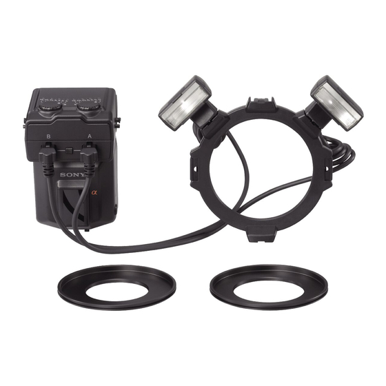
- Page 2 SPECIFICATIONS The macro twin flash kit provides flexible lighting for macro nature photography. It is ideal for close-up photography of flowers, insects, small objects, and so on. • Freedom to change the attachment position and angle of the flashtube enables more expressive photography. •...
-
Page 3: Table Of Contents
TABLE OF CONTENTS Section Title Page SERVICE NOTE 1-1. Chemicals ······································································· 1-1 1-2. Exterior Parts ·································································· 1-1 1-3. Unleaded Solder ····························································· 1-1 1-4. Safety Check-out ···························································· 1-2 DISASSEMBLY 2-1. Disassembly ··································································· 2-2 FRAME SCHEMATIC DIAGRAM 3-1. Frame Schematic Diagram ············································· 3-1 REPAIR PARTS LIST 4-1. -
Page 4: Service Note
1. SERVICE NOTE 1-1. Chemicals Some chemicals used for servicing are highly volatile. Their evaporation caused by improper management affects your health and environment, and wastes resources. Manage the chemicals carefully as follows. • Store chemicals sealed in a specific place to prevent from exposure to high temperature or direct sunlight. •... -
Page 5: Safety Check-Out
CRITIQUES POUR LA SÉCURITÉ DE FONCTIONNEMENT. NE COMPONENTS WITH SONY PARTS WHOSE PART NUMBERS REMPLACER CES COMPOSANTS QUE PAR DES PIÈSES SONY APPEAR AS SHOWN IN THIS MANUAL OR IN SUPPLEMENTS DONT LES NUMÉROS SONT DONNÉS DANS CE MANUEL OU PUBLISHED BY SONY. -
Page 6: Disassembly
2. DISASSEMBLY NOTE FOR REPAIR • Make sure that the flat cable and flexible board are not cracked of bent at the terminal. Cut and remove the part of gilt Do not insert the cable insufficiently nor crookedly. which comes off at the point. (Be careful or some •... - Page 7 2-1. DISASSEMBLY 2-1-1. BATTERY CASE UNIT AND SHOE FOOT UNIT EXPLODED VIEW 2 Side Rubber !\ Dials 4 Cover (B) 3 Side Rubber !; Cover (A) Set != Connector Socket Set 8 Bounce Shaft (A) Set Connector Cap (A) HELP03 ![ Cover (D) Set (See Page 3-2.) 5 Click...
- Page 8 2-1-2. COVER (D) SET EXPLODED VIEW Cover (D) Set Ornamental Sheet Label Battery Lid SP Click HVL-MT24AM...
- Page 9 HELP Note for assembling and grease applying positions are shown. HELP01 Apply the grease (G-85) to the instruction part as shown in the figure. Grease (G-85): J-6082-626-A Apply the grease (G-85) HELP02 Apply the grease (G-85) to the instruction part as shown in the figure. Grease (G-85): J-6082-626-A Apply the grease (G-85) Apply the grease (G-85)
- Page 10 HELP03 Apply the grease (G-85) to the instruction part as shown in the figure. Grease (G-85): J-6082-626-A Apply the grease (G-85) Apply the grease (G-85) HVL-MT24AM HELP...
-
Page 11: Frame Schematic Diagram
Ver 1.1 2007.01 3. FRAME SCHEMATIC DIAGRAM 3-1. FRAME SCHEMATIC DIAGRAM Cover (D) Set Cover (A) Set Connector Socket Set PC Board Set (D) PC Board (C) CM(A) 1/64 1/64 CM(B) 6 5 4 PC Board Set (G) Cover (D) Set CN10 0 7 6 CUT1... -
Page 12: Repair Parts List
4. REPAIR PARTS LIST DISASSEMBLY NOTE: • -XX and -X mean standardized parts, so they may • The mechanical parts with no reference number in have some difference from the original one. the exploded views are not supplied. • Items marked “*” are not stocked since they are seldom required for routine service. - Page 13 DISASSEMBLY 4-1-2. COVER (D) SET Ref. No. Part No. Description X-2176-753-1 COVER(D) SET 2-693-236-01 CLICK 2-691-289-01 LID (SP), BATTERY 3-095-590-01 LABEL 3-095-594-01 SHEET, ORNAMENTAL HVL-MT24AM...
-
Page 14: Supplied Accessories
Ver. 1.3 2015.06 The changed portions from Ver. 1.2 are shown in blue. 4-2. SUPPLIED ACCESSORIES Checking supplied accessories. Other accessories 2-889-493-01 MANUAL, INSTRUCTION (JAPANESE, ENGLISH, FRENCH) (J, US, CND) 2-889-493-11 MANUAL, INSTRUCTION (ENGLISH, FRENCH, GERMAN, ITALIAN, DUTCH) (AEP) 2-889-493-21 MANUAL, INSTRUCTION (ENGLISH, PORTUGUESE, SPANISH, SWEDISH, RUSSIAN) (AEP) 2-889-493-31 MANUAL, INSTRUCTION (ENGLISH, ARABIC, TRADITONAL CHINESE,... -
Page 15: Adjustments
5. ADJUSTMENTS Note: After the service repair, perform the adjustments referring to this section. 5-1. PREPARATIONS 5-1-1. Adjusting Items when Replacing the Parts When replacing the following part, perform the described check/adjustment. When replacing the Cover-D Assy: • 5-2. INITIALIZATION OF EEPROM (WRITING OF INITIAL VALUE) •... - Page 16 5-1-2. List of Service Tools and Equipments • DC Power Supply • Digital Multimeter • Camera DSLR-A100 Personal computer USB cord with Power supply (Note 1) connector adaptor 1-833-062-11 J-6082-602-A (Note 2) Fig. 5-1-1 Note 1: Personal Computer (PC) Windows2000 Professional/XP MEMORY: 40 M Byte or more recommended Hard disk free area: 15 M Byte or more recommended...
- Page 17 5-1-3. Flash Adjustment Program The flash adjustment program is required for the check/adjustment after the service repair. Prepare/start the flash adjustment program with the following steps. Equipment • Personal Computer (PC) • Camera DSLR-A100 • USB Cord With Connector • Flash Adjustment Program Note: Flash Adjustment Program is downloadable from the ESI homepage.
-
Page 18: Initialization Of Eeprom (Writing Of Initial Value)
5-2. INITIALIZATION OF EEPROM (WRITING OF INITIAL VALUE) Note: When replacing the PC board set, A, perform the EEPROM initialization before any adjustment. If dialog box of error code appears during the initialization, check the reason of error referring to page 5-12. Equipment •... - Page 19 [Initialize] Click the button. Fig. 5-2-5 [Yes] When checking message window “Do you really want to initialize EEPROM?” appears, click the button. Fig. 5-2-6 [OK] When completion message “Done.” appears after initialization, click the button. Fig. 5-2-7 [Exit] When the initialization is completed, click the button to go back the adjustment menu.
-
Page 20: Charging Voltage Adjustment
5-3. CHARGING VOLTAGE ADJUSTMENT Note: If dialog box of error code appears during the adjustment, check the reason of error referring to page 5-12. Equipment • Personal Computer (PC) • Camera DSLR-A100 • USB Cord With Connector • Flash Adjustment Program Note: Flash Adjustment Program is downloadable from the ESI homepage. - Page 21 2. Adjusting Method [Connect] Select the “HVL-MT24AM/Macro Controller” from the pull down menu of the flash adjustment program, then click the button. [End] Note: Click the button to terminate the flash adjustment program. Fig. 5-3-3 [Yes] When checking message window “You select HVL-MT24AM/Macro Controller” appears, click the button.
-
Page 22: Full-Charge Voltage/Stop Charge Voltage Check
5-4. FULL-CHARGE VOLTAGE/STOP CHARGE VOLTAGE CHECK Equipment • DC Power Supply • Digital Multimeter • Power Supply Adaptor 1. Preparations 1) Set the HSS of the flash to “OFF”. 2) Set the equipments as shown in the Fig. 5-4-1. Note: For connection method of power supply adaptor, refer to page 5-2. -
Page 23: Assist Mode
5-5. ASSIST MODE Note: If dialog box of error code appears during the setting, check the reason of error referring to page 5-12. 5-5-1. Displaying of Assist Mode Equipment • Personal Computer (PC) • Camera DSLR-A100 • USB Cord With Connector •... - Page 24 4) The assist mode window will appear. Fig. 5-5-5 HVL-MT24AM 5-10...
- Page 25 5-5-2. LCD/LED Displays Check Check the LCD/LED displays. Equipment • Personal Computer (PC) • Camera DSLR-A100 • USB Cord With Connector • Flash Adjustment Program Note: Flash Adjustment Program is downloadable from the ESI homepage. Checking Method Connect the checking flash to the camera. Display the assist mode window referring to “5-5-1.
-
Page 26: Error Code List
5-6. ERROR CODE LIST Error code Description Communication Error, Code#:E600 Communication error with the camera Code#:F000 Input data error to DLL file Code#:F100 Setting error of USB port Code#:2531 Communication error of main signal on the camera HVL-MT24AM 5-12... - Page 27 5-1-2. List of Service Tools and Equipments (See original service manual page 5-2) Personal computer USB cord with Power supply (Note 1) connector adaptor 1-833-062-11 J-6082-602-A (Note 2) Voltage confirmation cable J-6082-657-A Fig. 5-1-1 2007D0800-1 HVL-MT24AM © 2007.04 Sony EMCS Co. 9-852-155-82 Published by Kohda TEC...
- Page 28 & : Points added portion. 5-3. CHARGING VOLTAGE ADJUSTMENT (See original service manual page 5-6) Equipment • Personal Computer (PC) • Camera DSLR-A100 • USB Cord With Connector • Flash Adjustment Program Note: Flash Adjustment Program is downloadable from the ESI homepage. •...
- Page 29 & : Points added portion. 5-4. FULL-CHARGE VOLTAGE/STOP CHARGE VOLTAGE CHECK (See original service manual page 5-8) Equipment • DC Power Supply • Digital Multimeter • Power Supply Adaptor • Voltage Confirmation Cable The probe (–) of the digital multimeter can be connected to the negative line of the DC power supply.
- Page 30 [Description of main button functions on toolbar of the Adobe Acrobat Reader Ver5.0 (for Windows)] Toolbar Printing a text Reversing the screens displayed once • To reverse the previous screens (operation) one by one, click 1. Click the Print button 2.
- Page 31 Reverse 985215514.pdf Revision History S.M. Rev. Ver. Date History Contents issued 2006.11 Official Release — — 2007.01 Revised-1 • Addition of FRAME SCHEMATIC DIAGRAM 2007.04 Supplement-1 • Addition of Service Tool (S1 DI07-002) 2015.06 Revised-2 • Addition of SUPPLIED ACCESSORIES (A2 15-042) Page HVL-MT24AM...