
Related Manuals for Siemens FDCW241


Summary of Contents for Siemens FDCW241
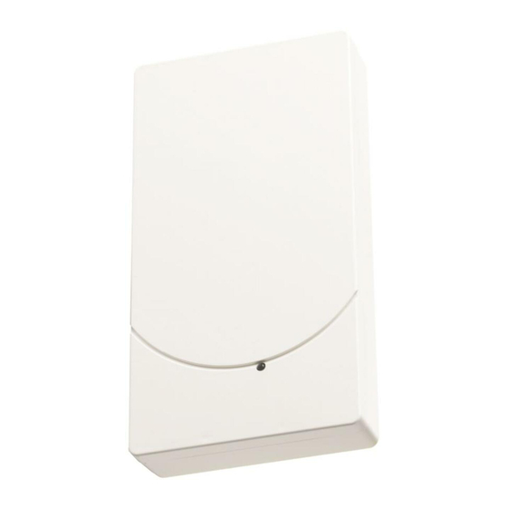
- Page 1 FDCW241 Radio gateway Mounting Smart Infrastructure A6V10227641_h_en_-- 2020-03-31...
- Page 2 All rights created by patent grant or registration of a utility model or design patent are reserved. Issued by: Siemens Switzerland Ltd. Smart Infrastructure Global Headquarters Theilerstrasse 1a CH-6300 Zug Tel. +41 58 724-2424 www.siemens.com/buildingtechnologies Edition: 2020-03-31 Document ID: A6V10227641_h_en_-- © Siemens Switzerland Ltd, 2012 2 | 20 A6V10227641_h_en_--...
-
Page 3: Table Of Contents
Table of contents About this document................. Mounting / Installation................Mounting....................Mounting in housing FDCH221 ..............Connecting the radio gateway ..............Details for ordering ................... Radio gateway FDCW221 ................ Connection terminal DBZ1190-AB ............Battery pack BAT3.6-10 ................Housing FDCH221 ................... Housing base FDCH271................Housing cover FDCH272................ - Page 4 4 | 20 A6V10227641_h_en_--...
-
Page 5: About This Document
You will find more information on the radio gateway FDCW241 in document A6V10227639. Intended use The radio gateway FDCW241 must only be used on a FDnet/C-NET detector line in a fire detection system FS20/FS720. ● Specialist electrical engineering knowledge is required for installation. -
Page 6: Mounting / Installation
Mounting / Installation Mounting 2 Mounting / Installation 2.1 Mounting Figure 1: Installing the radio gateway 1 Housing cover 2 Screw 3 Lock 4 Strain relief fastenings 5 Cable entries You have the radio gateway, battery pack, fixing screws, and cable tie to hand. You have the device location plan to hand. - Page 7 Mounting / Installation Mounting 7. Fasten the cable using a cable tie as strain relief (4). 8. Label the battery pack with the date. 9. Insert the battery pack and check the position of the battery cable. Do not connect the battery pack until you are ready to commission the radio cell. a The radio gateway is installed.
-
Page 8: Mounting In Housing Fdch221
Mounting / Installation Mounting in housing FDCH221 2.2 Mounting in housing FDCH221 The radio gateway can be installed in a separate housing FDCH221. The housing protects the radio gateway from dirt and dust. Ø max. 4.8 mm Figure 2: Installing housing FDCH221 1 Cable entry 4 Screws for securing the housing 2 Cables... -
Page 9: Connecting The Radio Gateway
Figure 4: Connections on radio gateway FDCW241 detector line terminal strip The radio gateway 'FDCW241' automatically assigns the additional, virtual address 'FDCL221v' as a line separator. When you assign the connections, you determine the order in which the devices are read in at the control panel. - Page 10 Mounting / Installation Connecting the radio gateway The following topologies are possible: Radio cell as LOOP FC20xx FC720x LOOP1_2- LOOP1_2+ LOOP1_1- LOOP1_1+ FC20xx FC720x LOOP1_2- LOOP1_2+ LOOP1_1- LOOP1_1+ Figure 5: Loop connection Radio cell as stub Figure 6: Stub connection only 10 | 20 A6V10227641_h_en_--...
- Page 11 Mounting / Installation Connecting the radio gateway Radio cell as sub-stub on loop Figure 7: Sub-stub on loop connection Wiring connections NOTICE Failure of the electrical connection Damage to the screw terminals or contact problems may lead to faults in the electrical connection. If the conductor cross-sections you want to connect to the radio gateway are larger than 1.5 mm², the screw terminals may become damaged or contact problems may arise.
-
Page 12: Details For Ordering
● Connector system with protection against polarity reversal ● Inscription field for commissioning date ● Compatible with: – Radio gateway FDCW241 – Radio manual call point FDM273 – Radio manual call point FDM275 – Radio manual call point FDM275(F) –... -
Page 13: Housing Fdch221
Multi line separator module FDCL221-M – Input module FDCI22x(-CN) – Input/output module FDCIO22x(-CN) – Output module FCA1209‑Z1 – Radio gateway FDCW241 – Zone module, external powered FDCI223, FDCI723 – Sounder module FCA2005-A1 ● Order number: S54312-F3-A1 3.5 Housing base FDCH271 ●... -
Page 14: Mcl-Usb (Radio) Adapter Fduz227
Interface converter for USB on MC link ● Compatible with: – Floor repeater terminal FT2010 – Floor repeater display FT2011 – Radio gateway FDCW221 and FDCW241 – Detector exchanger and tester FDUD292 – Intelligent detector tester FDUD293 – Line tester FDUL221 –... -
Page 15: Specifications
Specifications Technical data 4 Specifications Unless otherwise mentioned, the following data applies: Temperature = 25 °C Air pressure = 1000 hPa (750 Torr) You will find information on approvals on the data sheet for the device. 4.1 Technical data You will find information on approvals, CE marking, and the relevant EU directives for this device (these devices) in the following document(s);... - Page 16 Specifications Technical data Radio Number of radio devices per radio Max. 30 gateway as loop Number of radio devices per radio Max. 30 gateway as stub Sending/receiving aerials Dual band aerial Radio transmission: ● Frequency range 433.05…434.79 MHz in band 44b ¹ 868…870 MHz in band 48, 49, 50, 54, and 56b ¹...
- Page 17 Specifications Technical data Top band Bottom band Channel Frequency [MHz] Channel Frequency [MHz] 869.775 869.825 869.875 869.925 869.975 Battery pack BAT3.6-10 Lithium battery pack BAT3.6-10 LI-SOCl2 battery pack 3.6 V, 10 Ah Service life Over 6 years in normal operation If the normal detector line power supply fails, approx. 1 week Battery voltage monitored Weight...
-
Page 18: Dimensions
Specifications Dimensions 4.2 Dimensions Radio gateway FDCW241 4.3 Master gauge for recesses 44.5 44.5 39.5 39.5 18 | 20 A6V10227641_h_en_--... -
Page 19: Environmental Compatibility And Disposal
Specifications Environmental compatibility and disposal 4.4 Environmental compatibility and disposal This equipment is manufactured using materials and procedures which comply with current environmental protection standards as best as possible. More specifically, the following measures have been undertaken: ● Use of reusable materials ●... - Page 20 © Siemens Switzerland Ltd, 2012 Issued by Siemens Switzerland Ltd Technical specifications and availability subject to change without notice. Smart Infrastructure Global Headquarters Theilerstrasse 1a CH-6300 Zug +41 58 724 2424 www.siemens.com/buildingtechnologies A6V10227641_h_en_--...