Yamaha AG-Stomp Owner's Manual
Accoustic guitar pre-amplifier
Hide thumbs
Also See for AG-Stomp:
- Handleiding (32 pages) ,
- Service manual (45 pages) ,
- Patch list (1 page)
Table of Contents
Advertisement
Advertisement
Table of Contents

Related Manuals for Yamaha AG-Stomp


Summary of Contents for Yamaha AG-Stomp
- Page 1 Owner’s Manual...
- Page 2 Compliance with FCC regulations does * This applies only to products distributed by YAMAHA CORPORATION OF AMERICA. CANADA This Class B digital apparatus complies with Canadian ICES-003.
-
Page 3: Important Safety Instructions
Please make sure that benches are stable and any optional fixtures (where appli- cable) are well secured BEFORE using. Benches supplied by Yamaha are designed for seating only. No other uses are recom- mended. -
Page 4: Table Of Contents
Thank you for purchasing the YAMAHA AG-Stomp Acoustic Guitar Pre-Amplifier. Before you use the AG-Stomp, we urge you to take the time and read this Owner’s Manual carefully in order to get the most out of the device’s many functions and to ob- tain maximum life. -
Page 5: Precautions
• Do not apply excessive force to the switches, knobs and controls. • The AG-Stomp is a precision device. Handle it with care and avoid dropping or jarring it. • For safety, always remove the power adaptor from the AC wall outlet if there is any danger of lightning striking in your area. -
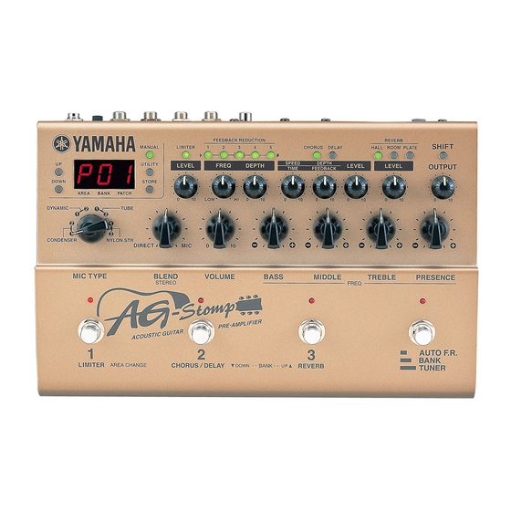
Page 6: Nomenclature
Nomenclature I Top Panel Display & Main Section G Display & Main Section q UP Button w DOWN Button Press to change the Patch Number by +/-1. Hold the button to change the Bank Number by +/-1. Si- multaneously press the [UP] and [DOWN] buttons to switch between the User ↔... - Page 7 Tone Control. (→ page !1 OUTPUT Level Control Controls the level of the signal delivered from the AG-Stomp’s output jacks (OUTPUT, PHONES). * The OUTPUT knob’s setting is not saved in memory. !2 SHIFT Button The button is used to enter the SHIFT mode in which the Mic Simulator’s stereo setting and the Tone...
- Page 8 @5 Bank Switch (AUTO F.R./BANK/TUNER) • Press the switch when feedback occurs: The AG-Stomp will automatically identify the prob- lem frequency and apply a notch filter. (→ page • Hold the switch until the display flashes: Use Footswitch 1 to change the Area, Footswitch 2 or 3 to select the Bank.
-
Page 9: I Rear Panel
AG-Stomp’s individual effects. (→ page 18) Also, AG-Stomp data saved in an external MIDI de- vice can be returned to the AG-stomp via this jack. (→ page 25) #1 Digital Output Jack (DIGITAL OUT) This jack is used to transmit the output of the AG- Stomp as digital data. -
Page 10: Connections
1. Use the supplied TRS-XLR converter cable to convert the AG-Stomp’s outputs (balanced TRS) to bal- anced XLR outputs. 2. Use a commercially available PA type TRS phone cable, to connect the AG-Stomp’s output jack to the balanced inputs of a mixer, power amplifier, etc. -
Page 11: I Connecting Headphones
I Digital Output The AG-Stomp is equipped with a digital output jack (COAXIAL, 44.1 kHz) that provides direct digital con- nection to the digital input jack on a digital mixer, MD recorder, etc. -
Page 12: Using The Ag-Stomp
(monaural ↔ monaural). Never connect the guitar to the AG-Stomp with the supplied TRS phone cable when the Guitar Power Supply function described below is not used. If the TRS phone cable is used and the +9V SUPPLY switch is switched “ON”, it may result in damage since a total of 18V will be supplied to the electric-acoustic guitar’s built-in pre-... -
Page 13: I Produce Sound
3. Play a chord on the guitar and rotate the OUT- PUT knob to the right to adjust the volume. * If clipping due to the input signal overloading the AG-Stomp’s circuit occurs, the BANK Switch Lamp will light. If this is the case, reduce the volume on the guitar, or adjust the AG-Stomp’s VOLUME, individual TONE control knobs... - Page 14 Try switching each of the Effect Blocks ON/OFF or try changing the effect. Also, try rotating knobs for each of the effects to change the character of the effect. The AG-Stomp’s effects section is divided into the following three blocks. • Limiter (LIMITER) • Chorus/Delay (CHORUS/DELAY) •...
- Page 15 * Mic Simulator settings are stored in patch data (MIC TYPE Select Switch Settings). * When the Volume and Tone controls are set to high, the signal may clip inside of the AG-Stomp. In this case, decrease the guitar’s volume, or adjust the AG-Stomp’s VOLUME, individual Tone Controls or individual Effect knobs. Also, if feedback occurs, please use the Feedback Reduction Function described on page 16.
- Page 16 Using the AG-Stomp G Feedback Reduction The AG-Stomp is equipped with a Feedback Re- duction Function to prevent feedback. Feedback is caused when a certain frequency or frequencies of the amplified sound causes the gui- tar to resonate thereby being re-amplified until a steady howl or whistle is heard.
-
Page 17: I Selecting Patches
When a PRESET AREA patch is selected, a “ will appear in the display’s hundred’s digit ( * When the AG-Stomp is shipped, both the PRESET AREA and USER AREA contain the same patch data. (Refer to the supplemental [Patch List]). - Page 18 Mode with the Area/Bank/Patch you just selected ready. * To cancel the Area/Bank/Patch you just selected, press the BANK switch. The AG-Stomp will return to its previous con- dition. G Using a MIDI Controller Patches in the AG-Stomp can also be selected by...
-
Page 19: I Storing Patches
The store operation is complete when all the lamps light. * Utility mode settings are not stored in individual patches, they are stored in the AG-Stomp’s memory as common settings for all parameters. * The OUTPUT knob’s setting is not stored in memory. Use the Volume knob to set differences in volume for situations like backing, soloing, etc. - Page 20 G Control the AG-Stomp From an Exter- nal MIDI Device An external MIDI device’s MIDI OUT jack, connected to the AG-Stomp’s MIDI IN jack via a MIDI cable can be used to control the AG-Stomp’s volume, tone or effect parameters (setting values).
-
Page 21: Effect Functions And Parameters
Limiter’s effect. When set to “0.0”, the Limiter will have no effect. Feedback Reduction The AG-Stomp provides a total of five Notch Filter circuits that can be used to control specified frequen- cies. Applied to frequencies that are the source of feed- back, these Notch Filters are used to prevent feed- back from occurring. -
Page 22: External Control Settings
A foot controller (expression pedal) (optional), such as the YAMAHA FC-7, connected to the AG-Stomp’s EXP. PEDAL jack lets you control the volume and tone of the AG-Stomp and effect parameters (setting values). These same parameters can also be controlled with MIDI control changes. -
Page 23: Tuner Mode
Tuner Mode This mode is used for tuning your guitar. In the Tuner Mode, the AG-Stomp operates like a chromatic auto tuner. I Enter the Tuner Mode To enter the Tuner Mode, use any one of the three methods described below. -
Page 24: Utility Mode
Utility Mode The Utility Mode is used for the AG-Stomp’s overall system settings for things such as the footswitch, MIDI, external controllers, EXP. PEDAL jack, etc. * In the following section, the abbreviation [FR 1] button refers to the [FEEDBACK REDUCTION 1] button, etc. - Page 25 PRG No. Use the [UP]/[DOWN] buttons to select the number. • : MIDI Program Change No. Press the [FR 1] button to set the AG-Stomp’s patch number. Just as in selecting a patch number in the Play Mode, use the [UP]/[DOWN] buttons or the Footswitches to select.
-
Page 26: I External Control Settings
When the Bulk Out is carried out from the external MIDI device, the AG-Stomp will receive the bulk data. * Use the AG-Stomp’s Play Mode to receive MIDI Bulk In data. When the MIDI Bulk In operation is carried out, the contents of the patches in the USER AREA will be rewritten. -
Page 27: I Feedback Reduction Operating Mode
G Set the Maximum Value of the EXP. Pedal Sets the maximum value that indicates the position of the EXP. Pedal. Press the [FR 1] button and use the [UP]/[DOWN] buttons to set the position ( You can also hold the [FR 1] button and move the EXP. -
Page 28: Error Messages
Error Messages If an error occurs during operation, one of the following error message numbers will appear in the display. Stop operation of the AG-Stomp and follow one of the solutions described below. : MIDI Receive Buffer Full CAUSE: Too much MIDI data is being received and the buffer is full SOLUTION: Try reducing the amount of data being sent, or break the data into smaller blocks. -
Page 29: Specifications
Specifications Digital Section • Full Digital Signal Processing • Mic Simulator: 8 Types • Feedback Reduction: 5-band • Digital Effects • Limiter • Digital Chorus, Digital Delay • Hall Reverb, Room Reverb, Plate Reverb • External Controller Function (EXP Pedal/MIDI): 8 Controllers/Parameters •... -
Page 30: Midi Implementation Chart
MIDI Implementation Chart... - Page 31 MIDI Implementation Chart...
- Page 32 V698590 Printed in Taiwan...