
Related Manuals for Bosch Rexroth IndraDrive CSB02


Summary of Contents for Bosch Rexroth IndraDrive CSB02
- Page 1 The Drive & Control Company IndraDrive Control Sections CSB02, CSE02, CSH02, CDB02 Project Planning Manual Edition 03 R911338962...
- Page 2 © Bosch Rexroth AG 2015 This document, as well as the data, specifications and other information set forth in it, are the exclusive property of Bosch Rexroth AG. It may not be re‐ produced or given to third parties without its consent.
-
Page 3: Table Of Contents
DOK-INDRV*-CXX02******-PR03-EN-P Bosch Rexroth AG I/143 IndraDrive Control Sections CSB02, CSE02, CSH02, CDB02 Table of Contents Table of Contents Page Introduction........................7 Documentation............................7 1.1.1 Changes.............................. 7 1.1.2 Overview - documentations......................... 8 Drive systems, system components....................8 Motors............................... 8 Cables.............................. 8 Firmware............................ - Page 4 II/143 Bosch Rexroth AG DOK-INDRV*-CXX02******-PR03-EN-P IndraDrive Control Sections CSB02, CSE02, CSH02, CDB02 Table of Contents Page 4.1.1 General Information........................... 25 4.1.2 Type Plates at the Drive Controller....................25 4.1.3 Control Section Type Plate........................ 26 4.1.4 Firmware Type Plate......................... 26 4.1.5 Control Panel Type Plate........................
- Page 5 DOK-INDRV*-CXX02******-PR03-EN-P Bosch Rexroth AG III/143 IndraDrive Control Sections CSB02, CSE02, CSH02, CDB02 Table of Contents Page X8 or X10, Encoder Emulation (EM Option)..................63 X22 P2, X23 P1, Multi-Ethernet (ET option)..................65 X30, PROFIBUS PB..........................66 X37, Digital Inputs/Outputs (DA Option)....................69 X38, analog inputs/outputs (DA option)....................
- Page 6 IV/143 Bosch Rexroth AG DOK-INDRV*-CXX02******-PR03-EN-P IndraDrive Control Sections CSB02, CSE02, CSH02, CDB02 Table of Contents Page 8.2.2 Incremental encoder emulation....................... 100 Connection........................... 100 Electrical data..........................101 8.2.3 Absolute encoder emulation (SSI format)..................102 Connection........................... 102 Electrical data..........................102 Pulse diagram..........................103 ET - Multi-Ethernet..........................
- Page 7 DOK-INDRV*-CXX02******-PR03-EN-P Bosch Rexroth AG V/143 IndraDrive Control Sections CSB02, CSE02, CSH02, CDB02 Table of Contents Page 9.2.1 General information......................... 129 9.2.2 Connection points with spring terminals..................129 9.2.3 Connection points with screw terminal blocks................. 129 Analog inputs/outputs: Shield connection................... 130 9.3.1...
- Page 8 VI/143 Bosch Rexroth AG DOK-INDRV*-CXX02******-PR03-EN-P IndraDrive Control Sections CSB02, CSE02, CSH02, CDB02...
-
Page 9: Introduction
DOK-INDRV*-CXX02******-PR03-EN-P Bosch Rexroth AG 7/143 IndraDrive Control Sections CSB02, CSE02, CSH02, CDB02 Introduction Introduction Documentation 1.1.1 Changes Changes in comparison to previ‐ Chapter Changes ous edition Introduction ● Updated overview of documentations Rexroth IndraDrive con‐ ● Added CSH02.xB-ET control section trol sections ●... -
Page 10: Overview - Documentations
8/143 Bosch Rexroth AG DOK-INDRV*-CXX02******-PR03-EN-P IndraDrive Control Sections CSB02, CSE02, CSH02, CDB02 Introduction 1.1.2 Overview - documentations Drive systems, system components Title Type of documentation Material number Document typecode Rexroth IndraDrive … R911… DOK-INDRV*-… Drive Systems with HMV01/02 Project Planning Manual... -
Page 11: Firmware
DOK-INDRV*-CXX02******-PR03-EN-P Bosch Rexroth AG 9/143 IndraDrive Control Sections CSB02, CSE02, CSH02, CDB02 Introduction Firmware Title Type of documentation Material number Document typecode Rexroth IndraDrive ... R911… DOK-INDRV*-… MPx-20 Application Manual MP*-20VRS**-APxx-EN-P 345608 Functions MPx-20 Release Notes MP*-20VRS**-RNxx-EN-P 345606 Version Notes... -
Page 12: Your Feedback
10/143 Bosch Rexroth AG DOK-INDRV*-CXX02******-PR03-EN-P IndraDrive Control Sections CSB02, CSE02, CSH02, CDB02 Introduction 1.1.3 Your feedback Your experience is important for our improvement processes of products and documentations. Inform us about mistakes you discovered in this documentation and changes you suggest; we would be grateful for your feedback. -
Page 13: Basic Design Of The Rexroth Indradrive Controllers
DOK-INDRV*-CXX02******-PR03-EN-P Bosch Rexroth AG 11/143 IndraDrive Control Sections CSB02, CSE02, CSH02, CDB02 Introduction Basic design of the Rexroth IndraDrive controllers 1.2.1 General information Power section Control section Fig. 1-1: Basic design of a Rexroth IndraDrive controller The drive controller consists of two essential parts: ●... -
Page 14: Esd Protection
12/143 Bosch Rexroth AG DOK-INDRV*-CXX02******-PR03-EN-P IndraDrive Control Sections CSB02, CSE02, CSH02, CDB02 Introduction ESD Protection Risk of damage to the control section and in‐ NOTICE terference with its operational safety caused by electrostatic charges! Exposed conductive parts coming into contact with the control section must be previously discharged by means of grounding. -
Page 15: Important Directions For Use
DOK-INDRV*-CXX02******-PR03-EN-P Bosch Rexroth AG 13/143 IndraDrive Control Sections CSB02, CSE02, CSH02, CDB02 Important directions for use Important directions for use Appropriate use 2.1.1 Introduction Rexroth products reflect the state-of-the-art in their development and their manufacture. They are tested prior to delivery to ensure operating safety and reliability. -
Page 16: Inappropriate Use
14/143 Bosch Rexroth AG DOK-INDRV*-CXX02******-PR03-EN-P IndraDrive Control Sections CSB02, CSE02, CSH02, CDB02 Important directions for use To ensure application-specific use of Drive controllers, device types of differ‐ ent drive power and different interfaces are available. Typical applications include, for example: ●... -
Page 17: Safety Instructions For Electric Drives And Controls
DOK-INDRV*-CXX02******-PR03-EN-P Bosch Rexroth AG 15/143 IndraDrive Control Sections CSB02, CSE02, CSH02, CDB02 Safety instructions for electric drives and controls Safety instructions for electric drives and controls Definitions of terms Application Documentation Application documentation comprises the entire documentation used to in‐... -
Page 18: General Information
16/143 Bosch Rexroth AG DOK-INDRV*-CXX02******-PR03-EN-P IndraDrive Control Sections CSB02, CSE02, CSH02, CDB02 Safety instructions for electric drives and controls requires. To comply with these qualifications, it is necessary, among other things, ● to be trained, instructed or authorized to switch electric circuits and devi‐... -
Page 19: Hazards By Improper Use
DOK-INDRV*-CXX02******-PR03-EN-P Bosch Rexroth AG 17/143 IndraDrive Control Sections CSB02, CSE02, CSH02, CDB02 Safety instructions for electric drives and controls ● Applications for functional safety are only allowed if clearly and explicitly specified in the application documentation "Integrated Safety Technolo‐ gy". If this is not the case, they are excluded. Functional safety is a safe‐... -
Page 20: Instructions With Regard To Specific Dangers
18/143 Bosch Rexroth AG DOK-INDRV*-CXX02******-PR03-EN-P IndraDrive Control Sections CSB02, CSE02, CSH02, CDB02 Safety instructions for electric drives and controls ● Health hazard for persons with heart pacemakers, metal implants and hearing aids in proximity to electric drive systems! ● Risk of burns by hot housing surfaces! ●... -
Page 21: Protective Extra-Low Voltage As Protection Against Electric Shock
DOK-INDRV*-CXX02******-PR03-EN-P Bosch Rexroth AG 19/143 IndraDrive Control Sections CSB02, CSE02, CSH02, CDB02 Safety instructions for electric drives and controls ● Secure built-in devices from penetrating foreign objects and water, as well as from direct contact, by providing an external housing, for exam‐... -
Page 22: Protection Against Dangerous Movements
20/143 Bosch Rexroth AG DOK-INDRV*-CXX02******-PR03-EN-P IndraDrive Control Sections CSB02, CSE02, CSH02, CDB02 Safety instructions for electric drives and controls Danger to life, risk of injury by electric shock! High electrical voltage by incor‐ rect connection! If extra-low voltage circuits of devices containing voltages and circuits of more than 50 volts (e.g., the mains connection) are connected to Rexroth... -
Page 23: Protection Against Electromagnetic And Magnetic Fields During Operation And Mounting
DOK-INDRV*-CXX02******-PR03-EN-P Bosch Rexroth AG 21/143 IndraDrive Control Sections CSB02, CSE02, CSH02, CDB02 Safety instructions for electric drives and controls ment works. Do not operate the machine if the emergency stopping switch is not working. ● Prevent unintended start-up. Isolate the drive power connection by means of OFF switches/OFF buttons or use a safe starting lockout. -
Page 24: Protection Against Contact With Hot Parts
22/143 Bosch Rexroth AG DOK-INDRV*-CXX02******-PR03-EN-P IndraDrive Control Sections CSB02, CSE02, CSH02, CDB02 Safety instructions for electric drives and controls tric drive and control system and the associated current-carrying con‐ ductors. 3.3.5 Protection against contact with hot parts Hot surfaces of components of the electric drive and control system. Risk of burns! ●... -
Page 25: Protection Against Pressurized Systems
DOK-INDRV*-CXX02******-PR03-EN-P Bosch Rexroth AG 23/143 IndraDrive Control Sections CSB02, CSE02, CSH02, CDB02 Safety instructions for electric drives and controls ● Do not throw batteries into open flames. ● Do not dismantle batteries. ● When replacing the battery/batteries, do not damage the electrical parts installed in the devices. -
Page 26: Explanation Of Signal Words And The Safety Alert Symbol
24/143 Bosch Rexroth AG DOK-INDRV*-CXX02******-PR03-EN-P IndraDrive Control Sections CSB02, CSE02, CSH02, CDB02 Safety instructions for electric drives and controls Explanation of signal words and the Safety alert symbol The Safety Instructions in the available application documentation contain specific signal words (DANGER, WARNING, CAUTION or NOTICE) and,... -
Page 27: Identifying The Control Section
DOK-INDRV*-CXX02******-PR03-EN-P Bosch Rexroth AG 25/143 IndraDrive Control Sections CSB02, CSE02, CSH02, CDB02 Identifying the Control Section Identifying the Control Section Type Plates 4.1.1 General Information Each drive component is marked by a type designation. There is a type plate attached to all devices. -
Page 28: Control Section Type Plate
26/143 Bosch Rexroth AG DOK-INDRV*-CXX02******-PR03-EN-P IndraDrive Control Sections CSB02, CSE02, CSH02, CDB02 Identifying the Control Section 4.1.3 Control Section Type Plate Type Material number Serial number Bar code Hardware index Production week (example: 13W38 means: year 2013, week Fig. 4-2: Control Section Type Plate (Example) 4.1.4... -
Page 29: Control Panel Type Plate
DOK-INDRV*-CXX02******-PR03-EN-P Bosch Rexroth AG 27/143 IndraDrive Control Sections CSB02, CSE02, CSH02, CDB02 Identifying the Control Section 4.1.5 Control Panel Type Plate Bar code Type Hardware index Factory identifier Production week (example: 13W38 means: year 2013, week Material number Serial number Fig. - Page 30 28/143 Bosch Rexroth AG DOK-INDRV*-CXX02******-PR03-EN-P IndraDrive Control Sections CSB02, CSE02, CSH02, CDB02...
-
Page 31: Rexroth Indradrive Control Sections
DOK-INDRV*-CXX02******-PR03-EN-P Bosch Rexroth AG 29/143 IndraDrive Control Sections CSB02, CSE02, CSH02, CDB02 Rexroth IndraDrive control sections Rexroth IndraDrive control sections Types 5.1.1 Overview Control section Type Features range ECONOMY CSE02.1A Single-axis control section; basic scope BASIC CSB02.1A Single-axis control section; basic scope CSB02.1B... -
Page 32: Functions And Interfaces
30/143 Bosch Rexroth AG DOK-INDRV*-CXX02******-PR03-EN-P IndraDrive Control Sections CSB02, CSE02, CSH02, CDB02 Rexroth IndraDrive control sections Functions and interfaces The control sections differ with regard to ● Configurability ● Available interfaces ● Cycle times or switching frequencies (pulse frequencies) CSE02.1A CSB02.1A... - Page 33 DOK-INDRV*-CXX02******-PR03-EN-P Bosch Rexroth AG 31/143 IndraDrive Control Sections CSB02, CSE02, CSH02, CDB02 Rexroth IndraDrive control sections CSE02.1A CSB02.1A CSB02.xB CSH02.xB-CC CSH02.xB-ET CDB02.1B Options CANopen (CN) – ✓ ✓ ✓ – – PROFIBUS (PB) – ✓ ✓ ✓ – ✓ Multi-Ethernet (ET) –...
-
Page 34: Dimensions
32/143 Bosch Rexroth AG DOK-INDRV*-CXX02******-PR03-EN-P IndraDrive Control Sections CSB02, CSE02, CSH02, CDB02 Rexroth IndraDrive control sections Dimensions Single-axis Double-axis Tab. 5-6: Dimensions Dimensions for mounting clearance to front: See documentation of power sections. -
Page 35: Cse02
DOK-INDRV*-CXX02******-PR03-EN-P Bosch Rexroth AG 33/143 IndraDrive Control Sections CSB02, CSE02, CSH02, CDB02 Rexroth IndraDrive control sections CSE02 5.4.1 Type code Short type designation 1 2 3 4 5 6 7 8 9 0 1 2 3 4 5 6 7 8 9... -
Page 36: Front View With Connection Points
34/143 Bosch Rexroth AG DOK-INDRV*-CXX02******-PR03-EN-P IndraDrive Control Sections CSB02, CSE02, CSH02, CDB02 Rexroth IndraDrive control sections 5.4.2 Front view with connection points Front view Connection Stranded Description point wire (example) [mm²] 0.25–0.5 Encoder evaluation EC X24 P2, Communication sercos III / EtherCAT X25 P1 0.75–1.5... -
Page 37: Csb02
DOK-INDRV*-CXX02******-PR03-EN-P Bosch Rexroth AG 35/143 IndraDrive Control Sections CSB02, CSE02, CSH02, CDB02 Rexroth IndraDrive control sections CSB02 5.5.1 CSB02.1 type code Short type designation 1 2 3 4 5 6 7 8 9 0 1 2 3 4 5 6 7 8 9... - Page 38 36/143 Bosch Rexroth AG DOK-INDRV*-CXX02******-PR03-EN-P IndraDrive Control Sections CSB02, CSE02, CSH02, CDB02 Rexroth IndraDrive control sections Short type designation 1 2 3 4 5 6 7 8 9 0 1 2 3 4 5 6 7 8 9 0 1 2 3 4 5 6 7 8 9...
-
Page 39: Csb02.5 Type Code
DOK-INDRV*-CXX02******-PR03-EN-P Bosch Rexroth AG 37/143 IndraDrive Control Sections CSB02, CSE02, CSH02, CDB02 Rexroth IndraDrive control sections 5.5.2 CSB02.5 type code Short type designation 1 2 3 4 5 6 7 8 9 0 1 2 3 4 5 6 7 8 9... -
Page 40: Front View With Connection Points
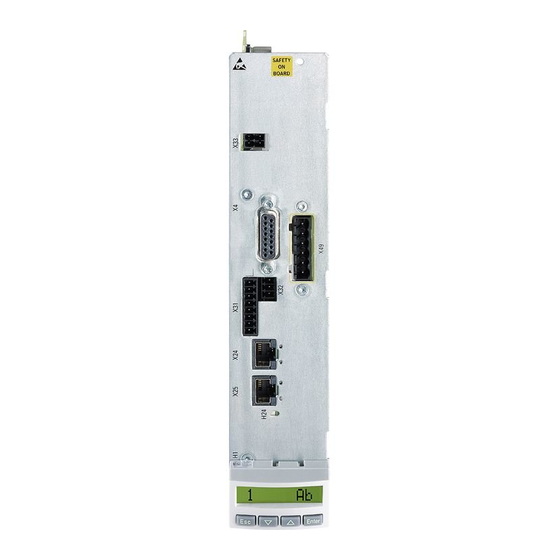
38/143 Bosch Rexroth AG DOK-INDRV*-CXX02******-PR03-EN-P IndraDrive Control Sections CSB02, CSE02, CSH02, CDB02 Rexroth IndraDrive control sections Only if interface 2 = PB or CN Only if interface 2 = PB, CN or EC Tab. 5-10: CSB02.5 type code The figure illustrates the basic structure of the type code. Our sales representative will help you with the current status of availa‐... -
Page 41: Cdb02
DOK-INDRV*-CXX02******-PR03-EN-P Bosch Rexroth AG 39/143 IndraDrive Control Sections CSB02, CSE02, CSH02, CDB02 Rexroth IndraDrive control sections CDB02 5.6.1 Type code Short type designation 1 2 3 4 5 6 7 8 9 0 1 2 3 4 5 6 7 8 9... - Page 42 40/143 Bosch Rexroth AG DOK-INDRV*-CXX02******-PR03-EN-P IndraDrive Control Sections CSB02, CSE02, CSH02, CDB02 Rexroth IndraDrive control sections Short type designation 1 2 3 4 5 6 7 8 9 0 1 2 3 4 5 6 7 8 9 0 1 2 3 4 5 6 7 8 9...
-
Page 43: Front View With Connection Points
DOK-INDRV*-CXX02******-PR03-EN-P Bosch Rexroth AG 41/143 IndraDrive Control Sections CSB02, CSE02, CSH02, CDB02 Rexroth IndraDrive control sections 5.6.2 Front view with connection points Front view Connection Stranded Description wire point (example) [mm²] X4.1 0.25–0.5 Encoder evaluation EC X4.2 0.25–0.5 Encoder evaluation EC... -
Page 44: Csh02
42/143 Bosch Rexroth AG DOK-INDRV*-CXX02******-PR03-EN-P IndraDrive Control Sections CSB02, CSE02, CSH02, CDB02 Rexroth IndraDrive control sections CSH02 5.7.1 CSH02.1 type code Short type designation 1 2 3 4 5 6 7 8 9 0 1 2 3 4 5 6 7 8 9... - Page 45 DOK-INDRV*-CXX02******-PR03-EN-P Bosch Rexroth AG 43/143 IndraDrive Control Sections CSB02, CSE02, CSH02, CDB02 Rexroth IndraDrive control sections Short type designation 1 2 3 4 5 6 7 8 9 0 1 2 3 4 5 6 7 8 9 0 1 2 3 4 5 6 7 8 9...
-
Page 46: Csh02.5 Type Code
44/143 Bosch Rexroth AG DOK-INDRV*-CXX02******-PR03-EN-P IndraDrive Control Sections CSB02, CSE02, CSH02, CDB02 Rexroth IndraDrive control sections 5.7.2 CSH02.5 type code Short type designation 1 2 3 4 5 6 7 8 9 0 1 2 3 4 5 6 7 8 9... - Page 47 DOK-INDRV*-CXX02******-PR03-EN-P Bosch Rexroth AG 45/143 IndraDrive Control Sections CSB02, CSE02, CSH02, CDB02 Rexroth IndraDrive control sections Short type designation 1 2 3 4 5 6 7 8 9 0 1 2 3 4 5 6 7 8 9 0 1 2 3 4 5 6 7 8 9...
-
Page 48: Front View With Connection Points
46/143 Bosch Rexroth AG DOK-INDRV*-CXX02******-PR03-EN-P IndraDrive Control Sections CSB02, CSE02, CSH02, CDB02 Rexroth IndraDrive control sections 5.7.3 Front view with connection points Front view Connection Stranded Description point wire (example) [mm²] 0.25–0.5 Encoder evaluation EC 0.25–0.5 Encoder evaluation EC Encoder emulation EM X10* 0.25–0.5... -
Page 49: On-Board Connection Points
DOK-INDRV*-CXX02******-PR03-EN-P Bosch Rexroth AG 47/143 IndraDrive Control Sections CSB02, CSE02, CSH02, CDB02 On-board connection points On-board connection points CSB02 interface equipment The number of on-board connection points of a CSB02 control section de‐ pends on the interface equipment (see type code): ●... -
Page 50: X4, Motor Encoder Connection
48/143 Bosch Rexroth AG DOK-INDRV*-CXX02******-PR03-EN-P IndraDrive Control Sections CSB02, CSE02, CSH02, CDB02 On-board connection points X4, Motor Encoder Connection View Identifica‐ Function tion Motor encoder connection D-Sub, 15-pin, female Unit Min. Max. Connection cable 0,25 Stranded wire Kind of encoder evaluation Tab. -
Page 51: X4.1, X4.2, Motor Encoder Connection
DOK-INDRV*-CXX02******-PR03-EN-P Bosch Rexroth AG 49/143 IndraDrive Control Sections CSB02, CSE02, CSH02, CDB02 On-board connection points Pin Assignment Connection Signal Function GND_shld Connection signal shields (internal shields) Track A analog positive Track A analog negative GND_Encoder Reference potential power supplies Track B analog positive... -
Page 52: X24 P2, X25 P1, Communication
50/143 Bosch Rexroth AG DOK-INDRV*-CXX02******-PR03-EN-P IndraDrive Control Sections CSB02, CSE02, CSH02, CDB02 On-board connection points X24 P2, X25 P1, communication Control section type Function ECONOMY sercos III, EtherCAT (S3) Communication module for sercos III and EtherCAT field bus systems BASIC Multi-Ethernet (ET) With the Multi-Ethernet communication module "ET", drive controllers can be integrated in differ‐... - Page 53 DOK-INDRV*-CXX02******-PR03-EN-P Bosch Rexroth AG 51/143 IndraDrive Control Sections CSB02, CSE02, CSH02, CDB02 On-board connection points View Connection Signal name Function Transmit, differential output A Transmit, differential output B Receive, differential input A n. c. n. c. Receive, differential input B n.
-
Page 54: X26, Engineering Interface
52/143 Bosch Rexroth AG DOK-INDRV*-CXX02******-PR03-EN-P IndraDrive Control Sections CSB02, CSE02, CSH02, CDB02 On-board connection points X26, Engineering interface Description Only available at CSH02.xB-CC ADVANCED devices. View Connection Signal name Function Transmit, differential output A Transmit, differential output B Receive, differential input A n. -
Page 55: X31 (Single-Axis), Digital Inputs, Digital Output
DOK-INDRV*-CXX02******-PR03-EN-P Bosch Rexroth AG 53/143 IndraDrive Control Sections CSB02, CSE02, CSH02, CDB02 On-board connection points X31 (single-axis), digital inputs, digital output View Connec‐ Signal name Function Default assignment tion Digital input Probe 1 (type B) Probe 2 Digital input E-Stop input... -
Page 56: X31 (Double-Axis), Digital Inputs, Digital Output
54/143 Bosch Rexroth AG DOK-INDRV*-CXX02******-PR03-EN-P IndraDrive Control Sections CSB02, CSE02, CSH02, CDB02 On-board connection points X31 (double-axis), digital inputs, digital output View Connec‐ Signal name Connec‐ Signal name Function Default assignment tion tion Digital input Probe (type B) I_10 Probe... -
Page 57: X32 (Single-Axis), Analog Input
DOK-INDRV*-CXX02******-PR03-EN-P Bosch Rexroth AG 55/143 IndraDrive Control Sections CSB02, CSE02, CSH02, CDB02 On-board connection points X32 (single-axis), analog input View Connec‐ Signal name Function tion GND_100 Connection for inner cable shield IA_1- Analog input IA_1+ Spring terminal (con‐ Unit min. -
Page 58: X32 (Double-Axis), Analog Input
56/143 Bosch Rexroth AG DOK-INDRV*-CXX02******-PR03-EN-P IndraDrive Control Sections CSB02, CSE02, CSH02, CDB02 On-board connection points X32 (double-axis), analog input View Connec‐ Signal name Connec‐ Signal name Function tion tion GND_100 GND_100 Connection for inner cable shield IA_1- IA_2- Analog input... -
Page 59: X33, Power Supply Of Digital I/Os, Bb Relay
DOK-INDRV*-CXX02******-PR03-EN-P Bosch Rexroth AG 57/143 IndraDrive Control Sections CSB02, CSE02, CSH02, CDB02 On-board connection points 6.10 X33, Power Supply of Digital I/Os, Bb Relay View Connec‐ Signal name Function tion 24V_EA Power supply of the digital inputs and outputs 0V_EA GND reference of the digital inputs and outputs Rel1.1... -
Page 60: X35, Digital And Analog Inputs/Outputs
58/143 Bosch Rexroth AG DOK-INDRV*-CXX02******-PR03-EN-P IndraDrive Control Sections CSB02, CSE02, CSH02, CDB02 On-board connection points 6.11 X35, digital and analog inputs/outputs View Connec‐ Signal name Connec‐ Signal name Function tion tion IA_2+ IA_3+ Analog input IA_2- IA_3- GND_100 GND_100 Connection for inner cable shield... -
Page 61: X36, Digital Inputs/Outputs, Analog Outputs
DOK-INDRV*-CXX02******-PR03-EN-P Bosch Rexroth AG 59/143 IndraDrive Control Sections CSB02, CSE02, CSH02, CDB02 On-board connection points 6.12 X36, digital inputs/outputs, analog outputs View Connec‐ Signal name Connec‐ Signal name Function tion tion OA_1 OA_2 Analog output GND_A1 GND_A2 GND reference of analog output... - Page 62 60/143 Bosch Rexroth AG DOK-INDRV*-CXX02******-PR03-EN-P IndraDrive Control Sections CSB02, CSE02, CSH02, CDB02...
-
Page 63: Optional Connection Points
DOK-INDRV*-CXX02******-PR03-EN-P Bosch Rexroth AG 61/143 IndraDrive Control Sections CSB02, CSE02, CSH02, CDB02 Optional connection points Optional connection points Overview Optional module Function Name of option Notes Connection point Communication CANopen CANopen field bus Applies to: BASIC CSB02.1B, ADVANCED PROFIBUS PROFIBUS field bus... -
Page 64: X8 Or X10, Encoder (Ec Option)
62/143 Bosch Rexroth AG DOK-INDRV*-CXX02******-PR03-EN-P IndraDrive Control Sections CSB02, CSE02, CSH02, CDB02 Optional connection points X8 or X10, Encoder (EC Option) Technical Data chapter 6.2 "X4, Motor Encoder Connection" on page 48... -
Page 65: X8 Or X10, Encoder Emulation (Em Option)
DOK-INDRV*-CXX02******-PR03-EN-P Bosch Rexroth AG 63/143 IndraDrive Control Sections CSB02, CSE02, CSH02, CDB02 Optional connection points X8 or X10, Encoder Emulation (EM Option) Description Emulation of absolute value and incremental encoder signals for further eval‐ uation by a control unit. The signals are galvanically isolated from the circuit board. - Page 66 64/143 Bosch Rexroth AG DOK-INDRV*-CXX02******-PR03-EN-P IndraDrive Control Sections CSB02, CSE02, CSH02, CDB02 Optional connection points Pin Assignment Connec‐ Signal Level Input/ Function Incremen‐ SSI en‐ Incremen‐ tion tal encod‐ coder tal encod‐ Output er with signal lev‐ el convert‐ n. c.
-
Page 67: X22 P2, X23 P1, Multi-Ethernet (Et Option)
DOK-INDRV*-CXX02******-PR03-EN-P Bosch Rexroth AG 65/143 IndraDrive Control Sections CSB02, CSE02, CSH02, CDB02 Optional connection points X22 P2, X23 P1, Multi-Ethernet (ET option) Tab. 7-4: Connection point Technical data chapter 6.4 "X24 P2, X25 P1, communication" on page 50... -
Page 68: X30, Profibus Pb
66/143 Bosch Rexroth AG DOK-INDRV*-CXX02******-PR03-EN-P IndraDrive Control Sections CSB02, CSE02, CSH02, CDB02 Optional connection points X30, PROFIBUS PB Description Fig. 7-1: PROFIBUS Interface View Identification Function PROFIBUS PB D-Sub, 9-pin, female Unit Min. Max. Connection cable 0,08 Stranded wire Tab. 7-5:... - Page 69 DOK-INDRV*-CXX02******-PR03-EN-P Bosch Rexroth AG 67/143 IndraDrive Control Sections CSB02, CSE02, CSH02, CDB02 Optional connection points Shield Bus connection and switch position for first node and last node Bus connection and switch position for all other nodes Fig. 7-2: Preparing a Cable for Connecting a Bus Connector To assemble the bus cable, proceed as follows: ●...
- Page 70 68/143 Bosch Rexroth AG DOK-INDRV*-CXX02******-PR03-EN-P IndraDrive Control Sections CSB02, CSE02, CSH02, CDB02 Optional connection points Terminating resistor is off Cable shield must have direct contact to metal Fig. 7-4: Bus Connection for all Other Slaves, Bus Connector With 9-pin D-Sub...
-
Page 71: X37, Digital Inputs/Outputs (Da Option)
DOK-INDRV*-CXX02******-PR03-EN-P Bosch Rexroth AG 69/143 IndraDrive Control Sections CSB02, CSE02, CSH02, CDB02 Optional connection points X37, Digital Inputs/Outputs (DA Option) View Connec‐ Signal name Function Connec‐ Signal name Function tion tion Digital input IO_1 Digital input/output IO_2 Digital output 24V_Ext... -
Page 72: X38, Analog Inputs/Outputs (Da Option)
70/143 Bosch Rexroth AG DOK-INDRV*-CXX02******-PR03-EN-P IndraDrive Control Sections CSB02, CSE02, CSH02, CDB02 Optional connection points X38, analog inputs/outputs (DA option) View Connec‐ Signal name Function Connec‐ Signal name Function tion tion GND_AnaEA GND reference IA_2+ Analog input OA_1 Analog output... -
Page 73: X41, Safe Motion Safety Technology
DOK-INDRV*-CXX02******-PR03-EN-P Bosch Rexroth AG 71/143 IndraDrive Control Sections CSB02, CSE02, CSH02, CDB02 Optional connection points X41, Safe Motion safety technology View Connec‐ Signal name Function tion SI_Out_Ch2 Safe output channel 2 Power supply of inputs/outputs (U SI_Out_Ch1 Safe output channel 1... -
Page 74: X42, X43, Safe Motion Safety Technology (Communication)
72/143 Bosch Rexroth AG DOK-INDRV*-CXX02******-PR03-EN-P IndraDrive Control Sections CSB02, CSE02, CSH02, CDB02 Optional connection points 7.10 X42, X43, Safe Motion safety technology (communication) View Identifica‐ Function tion Connection points for connecting the HSZ01 safety zone module and the safety zone nodes:... -
Page 75: X48, Sbc Safety Technology
DOK-INDRV*-CXX02******-PR03-EN-P Bosch Rexroth AG 73/143 IndraDrive Control Sections CSB02, CSE02, CSH02, CDB02 Optional connection points 7.12 X48, SBC safety technology View Connec‐ Signal name Function tion Ext_SI_bSBC_Ch2 Channel 2 brake control output Ext_Diag_I_Brake Channel 1 and channel 2 diagnostic input... -
Page 76: X49, Optional Safety Technology Safe Torque Off
74/143 Bosch Rexroth AG DOK-INDRV*-CXX02******-PR03-EN-P IndraDrive Control Sections CSB02, CSE02, CSH02, CDB02 Optional connection points 7.14 X49, optional safety technology Safe Torque Off View Connec‐ Signal name Function tion SI_Ch2 Input for selection of channel 2 Power supply of inputs/outputs... -
Page 77: X61, Canopen (Cn Option)
DOK-INDRV*-CXX02******-PR03-EN-P Bosch Rexroth AG 75/143 IndraDrive Control Sections CSB02, CSE02, CSH02, CDB02 Optional connection points 7.16 X61, CANopen (CN Option) Description Fig. 7-7: CANopen Connection Point Connec‐ Type Num‐ Type of de‐ Stranded wire Figure tion point ber of sign [mm²]... -
Page 78: Control Panels
76/143 Bosch Rexroth AG DOK-INDRV*-CXX02******-PR03-EN-P IndraDrive Control Sections CSB02, CSE02, CSH02, CDB02 Optional connection points 7.17 Control panels 7.17.1 Type code Short type designation 1 2 3 4 5 6 7 8 9 0 1 2 3 4 5 6 7 8 9... -
Page 79: Advanced Control Panel Hap01.1A
DOK-INDRV*-CXX02******-PR03-EN-P Bosch Rexroth AG 77/143 IndraDrive Control Sections CSB02, CSE02, CSH02, CDB02 Optional connection points 7.17.2 ADVANCED Control Panel HAP01.1A For a detailed description of the control panel, see the documen‐ tation "Application Manual, Functions" of the firmware used. Fig. 7-8: ADVANCED Control Panel HAP01.1A... -
Page 80: Standard Control Panel Hap01.1N
78/143 Bosch Rexroth AG DOK-INDRV*-CXX02******-PR03-EN-P IndraDrive Control Sections CSB02, CSE02, CSH02, CDB02 Optional connection points 7.17.3 Standard Control Panel HAP01.1N For a detailed description of the control panel, see the documen‐ tation "Application Manual, Functions" of the firmware used. In the future, the standard control panel HAP01.1N will be re‐... -
Page 81: Technical Data - Functions
DOK-INDRV*-CXX02******-PR03-EN-P Bosch Rexroth AG 79/143 IndraDrive Control Sections CSB02, CSE02, CSH02, CDB02 Technical data - functions Technical data - functions EC - standard encoder evaluation 8.1.1 Supported encoder systems Supported Encoder Systems Encoder systems with a supply voltage of 5 and 12 volt: ●... -
Page 82: Indradyn S Msk/Qsk Motors S1/M1, S2/M2, S3/M3, S5/M5 (12 V Supply Voltage)
80/143 Bosch Rexroth AG DOK-INDRV*-CXX02******-PR03-EN-P IndraDrive Control Sections CSB02, CSE02, CSH02, CDB02 Technical data - functions IndraDyn S MSK/QSK motors S1/M1, S2/M2, S3/M3, S5/M5 (12 V supply voltage) Properties Encoder systems of the MSK/QSK motors are HIPERFACE® (S1/M1, S3/M3, S5/M5) or EnDat 2.1 (S2/M2) encoder systems. -
Page 83: Hiperface® (12 V Supply Voltage)
DOK-INDRV*-CXX02******-PR03-EN-P Bosch Rexroth AG 81/143 IndraDrive Control Sections CSB02, CSE02, CSH02, CDB02 Technical data - functions HIPERFACE® (12 V supply voltage) See the connection diagram for how to connect the encoder system. Connection diagram Line cross section ≥ 0.5 mm²; observe allowed encoder cable length Line cross section ≥... -
Page 84: Endat 2.1 According To Heidenhain Standard (5 V Supply Voltage)
82/143 Bosch Rexroth AG DOK-INDRV*-CXX02******-PR03-EN-P IndraDrive Control Sections CSB02, CSE02, CSH02, CDB02 Technical data - functions EnDat 2.1 according to Heidenhain standard (5 V supply voltage) See the connection diagram for how to connect the encoder system. Connection diagram Line cross section ≥ 0.5 mm²; observe allowed encoder cable length Line cross section ≥... -
Page 85: Pp According To Heidenhain Standard (5 V Supply Voltage)
DOK-INDRV*-CXX02******-PR03-EN-P Bosch Rexroth AG 83/143 IndraDrive Control Sections CSB02, CSE02, CSH02, CDB02 Technical data - functions according to Heidenhain standard (5 V supply voltage) See the connection diagram for how to connect the encoder system. Connection diagram Line cross section ≥ 0.5 mm²; observe allowed encoder cable length Line cross section ≥... -
Page 86: 12 V Supply Voltage)
84/143 Bosch Rexroth AG DOK-INDRV*-CXX02******-PR03-EN-P IndraDrive Control Sections CSB02, CSE02, CSH02, CDB02 Technical data - functions (12 V supply voltage) See the connection diagram for how to connect the encoder system. Connection diagram Line cross section ≥ 0.5 mm²; observe allowed encoder cable length Line cross section ≥... -
Page 87: Ttl (5 V Supply Voltage)
DOK-INDRV*-CXX02******-PR03-EN-P Bosch Rexroth AG 85/143 IndraDrive Control Sections CSB02, CSE02, CSH02, CDB02 Technical data - functions TTL (5 V supply voltage) See the connection diagram for how to connect the encoder system. Connection diagram Line cross section ≥ 0.5 mm²; observe allowed encoder cable length Line cross section ≥... -
Page 88: Ttl (12 V Supply Voltage)
86/143 Bosch Rexroth AG DOK-INDRV*-CXX02******-PR03-EN-P IndraDrive Control Sections CSB02, CSE02, CSH02, CDB02 Technical data - functions TTL (12 V supply voltage) See the connection diagram for how to connect the encoder system. Connection diagram Line cross section ≥ 0.5 mm²; observe allowed encoder cable length Line cross section ≥... -
Page 89: Ssi (5 V Supply Voltage)
DOK-INDRV*-CXX02******-PR03-EN-P Bosch Rexroth AG 87/143 IndraDrive Control Sections CSB02, CSE02, CSH02, CDB02 Technical data - functions SSI (5 V supply voltage) See the connection diagram for how to connect the encoder system. Connection diagram Line cross section ≥ 0.5 mm²; observe allowed encoder cable length Line cross section ≥... -
Page 90: Ssi (12 V Supply Voltage)
88/143 Bosch Rexroth AG DOK-INDRV*-CXX02******-PR03-EN-P IndraDrive Control Sections CSB02, CSE02, CSH02, CDB02 Technical data - functions SSI (12 V supply voltage) See the connection diagram for how to connect the encoder system. Connection diagram Line cross section ≥ 0.5 mm²; observe allowed encoder cable length Line cross section ≥... -
Page 91: Combined Encoder For Ssi (5 V Supply Voltage)
DOK-INDRV*-CXX02******-PR03-EN-P Bosch Rexroth AG 89/143 IndraDrive Control Sections CSB02, CSE02, CSH02, CDB02 Technical data - functions Combined encoder for SSI (5 V supply voltage) The combined encoder for SSI is a combination of SSI and sin-cos encoder See the connection diagram for how to connect the encoder system. -
Page 92: Resolver Without Encoder Data Memory
90/143 Bosch Rexroth AG DOK-INDRV*-CXX02******-PR03-EN-P IndraDrive Control Sections CSB02, CSE02, CSH02, CDB02 Technical data - functions Resolver without encoder data memory See the connection diagram for how to connect the encoder system. Connection diagram Line cross section ≥ 0.5 mm²; observe allowed encoder cable length Line cross section ≥... -
Page 93: Hall Sensor Box Shl02.1 (12 V Supply Voltage)
DOK-INDRV*-CXX02******-PR03-EN-P Bosch Rexroth AG 91/143 IndraDrive Control Sections CSB02, CSE02, CSH02, CDB02 Technical data - functions Hall sensor box SHL02.1 (12 V supply voltage) See the connection diagram for how to connect the Hall sensor box SHL02.1. Connection diagram VCC_Encoder +12 V Fig. -
Page 94: Power Supply
92/143 Bosch Rexroth AG DOK-INDRV*-CXX02******-PR03-EN-P IndraDrive Control Sections CSB02, CSE02, CSH02, CDB02 Technical data - functions 8.1.3 Power supply 5 V power supply 5 V power supply Data Unit min. typ. max. DC output voltage +5V 5.25 Output current The sum of the power consumptions of all connected encoder systems (5 V / 12 V) should not exceed 6 W.. - Page 95 DOK-INDRV*-CXX02******-PR03-EN-P Bosch Rexroth AG 93/143 IndraDrive Control Sections CSB02, CSE02, CSH02, CDB02 Technical data - functions Data Unit min. typ. max. Output current (peak value) Output current (rms value) Tab. 8-3: Resolver encoder supply Switching off power supply via The "parking axis" firmware command (C1600) causes the encoder power firmware supply to be switched off.
-
Page 96: Encoder Cable Length
94/143 Bosch Rexroth AG DOK-INDRV*-CXX02******-PR03-EN-P IndraDrive Control Sections CSB02, CSE02, CSH02, CDB02 Technical data - functions 8.1.4 Encoder cable length Use lines with the same line cross section for encoder supply. Allowed encoder cable length for 5 If the encoder system used does not support the Sense function, the maxi‐... - Page 97 DOK-INDRV*-CXX02******-PR03-EN-P Bosch Rexroth AG 95/143 IndraDrive Control Sections CSB02, CSE02, CSH02, CDB02 Technical data - functions I [mA] Encoder current consumption l [m] Cable length Line cross sections 0.5 mm ; 1.0 mm Fig. 8-15: Maximum allowed encoder cable lengths for 12 V encoder systems...
-
Page 98: Technical Data Of Ec Encoder Evaluation
96/143 Bosch Rexroth AG DOK-INDRV*-CXX02******-PR03-EN-P IndraDrive Control Sections CSB02, CSE02, CSH02, CDB02 Technical data - functions 8.1.5 Technical data of EC encoder evaluation Input circuit for sine signals A+, A-, B+, B-, R+, R- Fig. 8-16: Input circuit for sine signals (block diagram) - Page 99 DOK-INDRV*-CXX02******-PR03-EN-P Bosch Rexroth AG 97/143 IndraDrive Control Sections CSB02, CSE02, CSH02, CDB02 Technical data - functions Differential input for resolver oper‐ Data Unit min. typ. max. ation Amplitude encoder signal sine Input resistance kOhm Converter width A/D converter Tab. 8-6:...
-
Page 100: Signal Assignment To The Actual Position Value
98/143 Bosch Rexroth AG DOK-INDRV*-CXX02******-PR03-EN-P IndraDrive Control Sections CSB02, CSE02, CSH02, CDB02 Technical data - functions 8.1.6 Signal assignment to the actual position value Signal designation Signal shape Actual position value (with de‐ Signal assignment fault setting) Sine (1 V Rotary motor: Increasing actual position val‐... - Page 101 DOK-INDRV*-CXX02******-PR03-EN-P Bosch Rexroth AG 99/143 IndraDrive Control Sections CSB02, CSE02, CSH02, CDB02 Technical data - functions The encoder signal assignment to the inputs is based on clock‐ wise rotation (front view toward motor shaft). ● Track A (A+, A-) advances track B (B+, B-) 90° electrically.
-
Page 102: Em - Encoder Emulation
100/143 Bosch Rexroth AG DOK-INDRV*-CXX02******-PR03-EN-P IndraDrive Control Sections CSB02, CSE02, CSH02, CDB02 Technical data - functions EM - Encoder emulation 8.2.1 Cables Data Symbol Unit max. Length (shielded cable) shield Length (unshielded cable) unshield Capacitance pF/m Tab. 8-8: Cables 8.2.2... -
Page 103: Electrical Data
DOK-INDRV*-CXX02******-PR03-EN-P Bosch Rexroth AG 101/143 IndraDrive Control Sections CSB02, CSE02, CSH02, CDB02 Technical data - functions Electrical data Single-ended Data Symbol Unit min. typ. max. Input voltage Current consumption at U 25 + 3×I - 2V Output voltage "high" Out_High Output voltage "low"... -
Page 104: Absolute Encoder Emulation (Ssi Format)
102/143 Bosch Rexroth AG DOK-INDRV*-CXX02******-PR03-EN-P IndraDrive Control Sections CSB02, CSE02, CSH02, CDB02 Technical data - functions 8.2.3 Absolute encoder emulation (SSI format) Connection Fig. 8-21: Output of absolute actual position values according to SSI format Fig. 8-22: Differential input circuit (block diagram) Electrical data Differential inputs, absolute encod‐... -
Page 105: Pulse Diagram
DOK-INDRV*-CXX02******-PR03-EN-P Bosch Rexroth AG 103/143 IndraDrive Control Sections CSB02, CSE02, CSH02, CDB02 Technical data - functions Data Symbol Unit min. typ. max. Output current Output frequency Load capacitance between output and 0 V Terminating resistor at load 150–180 Term Overload protection... -
Page 106: Multi-Ethernet
104/143 Bosch Rexroth AG DOK-INDRV*-CXX02******-PR03-EN-P IndraDrive Control Sections CSB02, CSE02, CSH02, CDB02 Technical data - functions ET - Multi-Ethernet 8.3.1 Display elements Two unicolor port LEDs Identification: e.g. H10, H11, H12, H13 Multicolor diagnostic LED Identification: e.g. H24, NET ST Fig. -
Page 107: Port Led
DOK-INDRV*-CXX02******-PR03-EN-P Bosch Rexroth AG 105/143 IndraDrive Control Sections CSB02, CSE02, CSH02, CDB02 Technical data - functions 8.3.2 Port LED EtherNet/IP LED: Color / flashing pat‐ Significance tern No connection No data transmission Data transmission running Permanently lit yellow Connection to network available Permanently lit green Tab. -
Page 108: Profinet Io
106/143 Bosch Rexroth AG DOK-INDRV*-CXX02******-PR03-EN-P IndraDrive Control Sections CSB02, CSE02, CSH02, CDB02 Technical data - functions PROFINET IO LED: Color / flashing pat‐ Significance tern No connection No data transmission Data transmission running Permanently lit yellow Connection to network available Permanently lit green Tab. -
Page 109: Diagnostic Led
DOK-INDRV*-CXX02******-PR03-EN-P Bosch Rexroth AG 107/143 IndraDrive Control Sections CSB02, CSE02, CSH02, CDB02 Technical data - functions 8.3.3 Diagnostic LED EtherNet/IP LED: Color / flashing pattern Significance The device does not have a valid IP address or has been switched off. -
Page 110: Ethercat
108/143 Bosch Rexroth AG DOK-INDRV*-CXX02******-PR03-EN-P IndraDrive Control Sections CSB02, CSE02, CSH02, CDB02 Technical data - functions EtherCAT Significance Description LED: Color / flashing pattern Status ● Cyclic process data and acyclic data channel are not transmitted INIT ● No error... -
Page 111: Sercos Iii
DOK-INDRV*-CXX02******-PR03-EN-P Bosch Rexroth AG 109/143 IndraDrive Control Sections CSB02, CSE02, CSH02, CDB02 Technical data - functions sercos III Description LED: Color / flashing pattern Prio NRT mode (no sercos communication) CP0 (communication phase 0 active) Permanently lit orange CP1 (communication phase 1 active) -
Page 112: Profinet Io
110/143 Bosch Rexroth AG DOK-INDRV*-CXX02******-PR03-EN-P IndraDrive Control Sections CSB02, CSE02, CSH02, CDB02 Technical data - functions PROFINET IO LED: Color / flashing pattern Significance The device does not have a valid IP address or has been switched off. The device has run up with a valid IP address, but does not have a cyclic connection. -
Page 113: Pb - Profibus
DOK-INDRV*-CXX02******-PR03-EN-P Bosch Rexroth AG 111/143 IndraDrive Control Sections CSB02, CSE02, CSH02, CDB02 Technical data - functions PB - PROFIBUS Signal Specification Signal Specification +5 V (±10%) Repeater supply Max. 75 mA Repeater control signal TTL-compatible: ● 1: Transmit ● 0: Receive Output resistance: 350R ≤... -
Page 114: Cn - Canopen
112/143 Bosch Rexroth AG DOK-INDRV*-CXX02******-PR03-EN-P IndraDrive Control Sections CSB02, CSE02, CSH02, CDB02 Technical data - functions CN - CANopen Display Elements CANopen Significance Color Description Signals operating states; see Functional Description of firmware Green Error Signals error states; see Functional De‐... -
Page 115: Sx - Safe Motion, Safe Motion Bus
DOK-INDRV*-CXX02******-PR03-EN-P Bosch Rexroth AG 113/143 IndraDrive Control Sections CSB02, CSE02, CSH02, CDB02 Technical data - functions Sx - Safe Motion, Safe Motion Bus 8.6.1 Display elements Bicolor LED: Safety technology status Bicolor LED: Connection status X41, X42, X43 Not available for "Safe Motion Bus" option Fig. - Page 116 114/143 Bosch Rexroth AG DOK-INDRV*-CXX02******-PR03-EN-P IndraDrive Control Sections CSB02, CSE02, CSH02, CDB02 Technical data - functions Color / flashing pattern Safety technology status Connection status (Safety Supervisor State / Event) ● Not active ● Not ready ● Safety bus communication not con‐...
-
Page 117: Digital Inputs/Outputs
DOK-INDRV*-CXX02******-PR03-EN-P Bosch Rexroth AG 115/143 IndraDrive Control Sections CSB02, CSE02, CSH02, CDB02 Technical data - functions Digital inputs/outputs 8.7.1 General Information The digital inputs/outputs correspond to "IEC 61131". Do not operate digital outputs at low-resistance sources! In the Functional Description of the firmware, observe the Notes on Commissioning for digital inputs/outputs. -
Page 118: Digital Inputs Type B (Probe)
116/143 Bosch Rexroth AG DOK-INDRV*-CXX02******-PR03-EN-P IndraDrive Control Sections CSB02, CSE02, CSH02, CDB02 Technical data - functions Digital inputs type B (probe) Function See "Probe" in the Functional Description of the firmware. Technical data Fig. 8-27: Symbol Data Unit min. max. -
Page 119: Digital Inputs (Safety Technology L Options)
DOK-INDRV*-CXX02******-PR03-EN-P Bosch Rexroth AG 117/143 IndraDrive Control Sections CSB02, CSE02, CSH02, CDB02 Technical data - functions Digital inputs (safety technology L options) The digital inputs correspond to IEC 61131, type 2. Fig. 8-29: Symbol Data Unit Min. Max. Allowed input voltage... -
Page 120: Digital Inputs (Safety Technology S Options)
118/143 Bosch Rexroth AG DOK-INDRV*-CXX02******-PR03-EN-P IndraDrive Control Sections CSB02, CSE02, CSH02, CDB02 Technical data - functions Digital Inputs (Safety Technology S Options) The digital inputs correspond to IEC 61131, type 1. Data Unit Min. Max. Allowed input voltage High Current consumption Tab. -
Page 121: Digital Outputs
DOK-INDRV*-CXX02******-PR03-EN-P Bosch Rexroth AG 119/143 IndraDrive Control Sections CSB02, CSE02, CSH02, CDB02 Technical data - functions 8.7.3 Digital Outputs Digital Outputs (Standard) The digital outputs are compatible with digital inputs of types 1, 2 and 3 (IEC 61131). Fig. 8-30:... -
Page 122: Digital Outputs (Safety Technology L Options)
120/143 Bosch Rexroth AG DOK-INDRV*-CXX02******-PR03-EN-P IndraDrive Control Sections CSB02, CSE02, CSH02, CDB02 Technical data - functions Digital Outputs (Safety Technology L Options) The digital outputs are compatible with digital inputs of types 1, 2 and 3 (IEC 61131). Fig. 8-31:... -
Page 123: Digital Outputs (Safety Technology S Options)
DOK-INDRV*-CXX02******-PR03-EN-P Bosch Rexroth AG 121/143 IndraDrive Control Sections CSB02, CSE02, CSH02, CDB02 Technical data - functions Digital Outputs (Safety Technology S Options) The digital outputs are compatible with digital inputs of types 1, 2 and 3 (IEC 61131). Data Unit Min. - Page 124 122/143 Bosch Rexroth AG DOK-INDRV*-CXX02******-PR03-EN-P IndraDrive Control Sections CSB02, CSE02, CSH02, CDB02 Technical data - functions Time Behavior Description Unit Min. Max. Test pulse width (t μs Periodic time (T 1000 Phase shift between two test pulses on both channels (φ)
-
Page 125: Analog Voltage Input
DOK-INDRV*-CXX02******-PR03-EN-P Bosch Rexroth AG 123/143 IndraDrive Control Sections CSB02, CSE02, CSH02, CDB02 Technical data - functions Analog Voltage Input Analog/digital converter Fig. 8-32: Analog Voltage Input Data Unit Min. Typ. Max. Allowed input voltage Working range input voltage U on_work Input resistance R kΩ... -
Page 126: Analog Current Input
124/143 Bosch Rexroth AG DOK-INDRV*-CXX02******-PR03-EN-P IndraDrive Control Sections CSB02, CSE02, CSH02, CDB02 Technical data - functions Analog Current Input Analog/digital converter Fig. 8-33: Analog Current Input Data Unit Min. Typ. Max. Allowed input current Working range input current I on_work Input resistance R Ω... -
Page 127: Analog Output
DOK-INDRV*-CXX02******-PR03-EN-P Bosch Rexroth AG 125/143 IndraDrive Control Sections CSB02, CSE02, CSH02, CDB02 Technical data - functions 8.10 Analog Output Data Unit Typ. Output voltage Output load, ohmic kΩ Output load, capacitive Resolution mV/incr Conversion time (incl. response µs time) Output clock Position controller clock Precision (in relation to the measur‐... -
Page 128: Relay Contacts
126/143 Bosch Rexroth AG DOK-INDRV*-CXX02******-PR03-EN-P IndraDrive Control Sections CSB02, CSE02, CSH02, CDB02 Technical data - functions 8.11 Relay Contacts 8.11.1 Relay Contact Type 2 Fig. 8-34: Relay contact Data Unit Min. Typ. Max. Current carrying capacity 1000 Voltage load capacity Contact resistance at minimum cur‐... -
Page 129: Technical Data - Other
DOK-INDRV*-CXX02******-PR03-EN-P Bosch Rexroth AG 127/143 IndraDrive Control Sections CSB02, CSE02, CSH02, CDB02 Technical data - other Technical data - other Power consumption 9.1.1 General information The power consumption of the control sections consists of the following com‐ ponents: ● Basic equipment ●... -
Page 130: Optional Modules
128/143 Bosch Rexroth AG DOK-INDRV*-CXX02******-PR03-EN-P IndraDrive Control Sections CSB02, CSE02, CSH02, CDB02 Technical data - other 9.1.3 Optional modules Optional module Power consumption Option CANopen communication Multi-encoder systems Emulation of absolute and incremental encoders Multi-Ethernet Safe Torque Off PROFIBUS-DP communication... -
Page 131: Connection Points
DOK-INDRV*-CXX02******-PR03-EN-P Bosch Rexroth AG 129/143 IndraDrive Control Sections CSB02, CSE02, CSH02, CDB02 Technical data - other Connection points 9.2.1 General information The connection points at control sections are equipped with spring terminals and screw terminal blocks. To connect 2 conductors in one terminal connecting point: ●... -
Page 132: Analog Inputs/Outputs: Shield Connection
130/143 Bosch Rexroth AG DOK-INDRV*-CXX02******-PR03-EN-P IndraDrive Control Sections CSB02, CSE02, CSH02, CDB02 Technical data - other Analog inputs/outputs: Shield connection 9.3.1 Analog input Analog input of the drive controller; only connect the inner shield of the connection cable to the drive controller if GND has not been connected to ground in the external device. -
Page 133: Accessories
DOK-INDRV*-CXX02******-PR03-EN-P Bosch Rexroth AG 131/143 IndraDrive Control Sections CSB02, CSE02, CSH02, CDB02 Accessories Accessories There are the following accessories for control sections: ● HSZ01 safety zone module With the HSZ01 safety zone module it is possible to set up a safety zone with a maximum of 26 drive units. - Page 134 132/143 Bosch Rexroth AG DOK-INDRV*-CXX02******-PR03-EN-P IndraDrive Control Sections CSB02, CSE02, CSH02, CDB02...
-
Page 135: Environmental Protection And Disposal
DOK-INDRV*-CXX02******-PR03-EN-P Bosch Rexroth AG 133/143 IndraDrive Control Sections CSB02, CSE02, CSH02, CDB02 Environmental protection and disposal Environmental protection and disposal 11.1 Environmental protection Production processes The products are made with energy- and resource-optimized production pro‐ cesses which allow re-using and recycling the resulting waste. We regularly try to replace pollutant-loaded raw materials and supplies by more environ‐... - Page 136 134/143 Bosch Rexroth AG DOK-INDRV*-CXX02******-PR03-EN-P IndraDrive Control Sections CSB02, CSE02, CSH02, CDB02 Environmental protection and disposal Metals contained in electric and electronic modules can also be recycled by means of special separation processes. Products made of plastics can contain flame retardants. These plastic parts are labeled according to EN ISO 1043.
-
Page 137: Service And Support
DOK-INDRV*-CXX02******-PR03-EN-P Bosch Rexroth AG 135/143 IndraDrive Control Sections CSB02, CSE02, CSH02, CDB02 Service and support Service and support Our worldwide service network provides an optimized and efficient support. Our experts offer you advice and assistance should you have any queries. - Page 138 136/143 Bosch Rexroth AG DOK-INDRV*-CXX02******-PR03-EN-P IndraDrive Control Sections CSB02, CSE02, CSH02, CDB02...
-
Page 139: Index
DOK-INDRV*-CXX02******-PR03-EN-P Bosch Rexroth AG 137/143 IndraDrive Control Sections CSB02, CSE02, CSH02, CDB02 Index Index 0 … 9 RKG4200............80 CANopen 1Vpp Bus length............ 112 Encoder, 5 V supply voltage......83 Connection point X61........75 Encoder, 12 V supply voltage......84 Display elements.......... - Page 140 138/143 Bosch Rexroth AG DOK-INDRV*-CXX02******-PR03-EN-P IndraDrive Control Sections CSB02, CSE02, CSH02, CDB02 Index With spring terminals, notes......129 Connection point X31 (double-axis)....54 Contained substances Connection point X31 (single-axis)....53 see "Significant components"...... 133 Connection point X35........58 Control panel Connection point X36........
- Page 141 DOK-INDRV*-CXX02******-PR03-EN-P Bosch Rexroth AG 139/143 IndraDrive Control Sections CSB02, CSE02, CSH02, CDB02 Index 5 V power supply........... 92 12 V power supply......... 92 LED.............. 104 Cable length........... 94 H25, H26 Combined encoder for SSI, 5 V supply LED (Safe Motion)........113 voltage............
- Page 142 140/143 Bosch Rexroth AG DOK-INDRV*-CXX02******-PR03-EN-P IndraDrive Control Sections CSB02, CSE02, CSH02, CDB02 Index Mounting Power consumption Control section..........11 Basic circuit board of control section... 127 MSK/QSK encoder interface Optional modules......... 128 For S1/M1, S2/M2, S3/M3, S5/M5 encod‐ Power dissipation er systems............
- Page 143 DOK-INDRV*-CXX02******-PR03-EN-P Bosch Rexroth AG 141/143 IndraDrive Control Sections CSB02, CSE02, CSH02, CDB02 Index SB..............61 Safe Torque Off Encoder, 5 V supply voltage......85 L3..............74 Encoder, 12 V supply voltage......86 X49..............74 Type code X49.1, X49.2..........74 ADVANCED CSH02.1........42 Safety instructions for electric drives and ADVANCED CSH02.5........
- Page 144 142/143 Bosch Rexroth AG DOK-INDRV*-CXX02******-PR03-EN-P IndraDrive Control Sections CSB02, CSE02, CSH02, CDB02 Index Digital and analog inputs/outputs....58 Digital inputs/outputs, analog outputs.... 59 Digital inputs/outputs........69 Analog inputs/outputs........70 Optional safety technology Safe Motion..71 X41.1, X41.2 Optional safety technology Safe Motion..71...
- Page 145 DOK-INDRV*-CXX02******-PR03-EN-P Bosch Rexroth AG 143/143 IndraDrive Control Sections CSB02, CSE02, CSH02, CDB02 Notes...
- Page 146 The Drive & Control Company Bosch Rexroth AG Electric Drives and Controls P.O. Box 13 57 97803 Lohr, Germany Bgm.-Dr.-Nebel-Str. 2 97816 Lohr, Germany Tel. +49 9352 18 0 +49 9352 18 8400 www.boschrexroth.com/electrics DOK-INDRV*-CXX02******-PR03-EN-P...