
Related Manuals for Siemens POS8.4420/414


Summary of Contents for Siemens POS8.4420/414
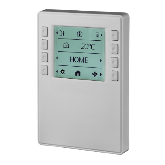
- Page 1 Room operating unit for Flexit POS8.4420/414 Building Technologies A6V10958126_en--_a 2017-06-30...
-
Page 2: Table Of Contents
Fan speed settings page ................22 Supply air temperature settings page ............22 General settings page ................23 Prolongation functions ................24 Expert mode ....................24 Standby page .................... 26 Appendix....................27 Parameters ....................27 2 | 29 Siemens Industry, Inc. A6V10958126_en--_a Building Technologies 2017-06-30... -
Page 3: About This Document
Copyright This document may be duplicated and distributed only with the express permission of Siemens, and may be passed on only to authorized persons or companies with the required technical knowledge. Quality assurance These documents were prepared with great care. -
Page 4: Reference Documents
About this document Reference documents 1.3 Reference documents Ref. Document title Document number Data sheet A6V10733771 Mounting instructions A6V10733764 4 | 29 Siemens Industry, Inc. A6V10958126_en--_a Building Technologies 2017-06-30... -
Page 5: Product Overview
Keys for adjustment of the room temperature setpoint, supply air/exhaust air fan control, time settings, etc. ● LCD display of room temperature, operating modes, and time. ● 2-wire interface to the controller through KNX PL-Link 2.3 System topology 5 | 29 A6V10958126_en--_a Siemens Industry, Inc. Building Technologies 2017-06-30... -
Page 6: Mechanical Design
KNX PL-Link (positive) KNX PL-Link (negative) To find the location of the KNX PL-Link plug, refer to the Mechanical design . NOTICE! You can choose either pair of pins to connect. 6 | 29 Siemens Industry, Inc. A6V10958126_en--_a Building Technologies 2017-06-30... - Page 7 KNX PL-Link (positive) KNX PL-Link (negative) RJ45 plug of the tool cable Connector Description Description CE+, KNX Voltage 16V CE-, KNX N.C. N.C. Ident'pin N.C. NOTE: De-energize the controller before wiring POS8.4420/414. 7 | 29 A6V10958126_en--_a Siemens Industry, Inc. Building Technologies 2017-06-30...
- Page 8 ● Directly to the room automation station ● To the room unit using the tool cable and the OCI702 service interface (see data sheet A6V10438951) 8 | 29 Siemens Industry, Inc. A6V10958126_en--_a Building Technologies 2017-06-30...
-
Page 9: Dimensions
Product overview Dimensions 2.6 Dimensions 9 | 29 A6V10958126_en--_a Siemens Industry, Inc. Building Technologies 2017-06-30... -
Page 10: Important Information On Safety And Disposal
● Third-party regulations, for example, by the general contractor or building owner. The electrical safety for building automation and control systems by Siemens is essentially based on safely separating low voltage from mains voltage. 3.2 Device-specific regulations KNX bus supply Note permissible line lengths and topologies when planning and installing controllers and field devices featuring KNX bus connection. -
Page 11: Disposal
Directive 2012/19/EU and may not be disposed of as domestic garbage. ● Dispose of the device through channels provided for this purpose. ● Comply with all local and currently applicable laws and regulations. 11 | 29 A6V10958126_en--_a Siemens Industry, Inc. Building Technologies 2017-06-30... -
Page 12: Mounting And Installation
Check package contents Check the package content for visible signs of transport damage and for completeness. Do not install parts damaged during shipment. Contact your Siemens representative in the event of damaged parts. Check operating Note the information in the data sheet of these operating instructions before... -
Page 13: Mounting Instructions
Keep a distance of at least 20 mm from the base plate to any object above the base plate, such as some cable ducts, so that the device cover can be snapped onto the base plate. Panel mounting 13 | 29 A6V10958126_en--_a Siemens Industry, Inc. Building Technologies 2017-06-30... - Page 14 Mounting and installation Mounting instructions Dismounting/service 14 | 29 Siemens Industry, Inc. A6V10958126_en--_a Building Technologies 2017-06-30...
-
Page 15: Commissioning
After releasing the programming pin, testing of the KNX PL-Link connection starts; the service LED flashes (1/4s on, 7/4s off). After approximately 12 seconds, the test result is displayed: 15 | 29 A6V10958126_en--_a Siemens Industry, Inc. Building Technologies 2017-06-30... - Page 16 If the bus plug remains connected, the device acts like a newly inserted device requiring automated or manual configuration. NOTICE This operation resets all user-defined data and configuration settings to factory default. This operation is irreversible. 16 | 29 Siemens Industry, Inc. A6V10958126_en--_a Building Technologies 2017-06-30...
-
Page 17: Technical Data
Air humidity <85% rh ● Transport ● Environmental Conditions: Class 2K3 Temperature -25...70°C (-4... 158 F) Air humidity <95% rh Mechanical ambient conditions Normal operation Class 3M2 Transport Class 2M2 17 | 29 A6V10958126_en--_a Siemens Industry, Inc. Building Technologies 2017-06-30... - Page 18 Connect the device into and outlet on a circuit different from that to which the receiver is connected. ● Consult the dealer or an experienced radio/TV technician for help. General data Color Signal white (RAL9003) Weight 150g 18 | 29 Siemens Industry, Inc. A6V10958126_en--_a Building Technologies 2017-06-30...
-
Page 19: Functions
Alarm notification OK, but not acknowledged Alarm notification acknowledged Alarm notification, normal, acknowledged Service notification Service notification ok, but not acknowledged Service notification acknowledged To confirm To cancel Go back 19 | 29 A6V10958126_en--_a Siemens Industry, Inc. Building Technologies 2017-06-30... - Page 20 Functions Elements Functions General settings page Home page Fan speed settings page Supply air temperature settings page Alarm list is empty Read parameter mode 20 | 29 Siemens Industry, Inc. A6V10958126_en--_a Building Technologies 2017-06-30...
-
Page 21: Operation
Toggle between TSP and Away mode Button 5 Enter the prolongation function settings page Button 4 and 8 Toggle through different pages: Home, Fan Speed Settings, Supply Air Temperature Settings and General Settings. 21 | 29 A6V10958126_en--_a Siemens Industry, Inc. Building Technologies 2017-06-30... -
Page 22: Fan Speed Settings Page
No function (no arrow symbols displayed) Button 7 Enable/disable electrical heater Button 4 and 8 Toggle through different pages: Home, Fan Speed Settings, Supply Air Temperature Settings and General Settings. 22 | 29 Siemens Industry, Inc. A6V10958126_en--_a Building Technologies 2017-06-30... -
Page 23: General Settings Page
Enable/disable the Auto mode Button 3 and 7 No function (no arrow symbols displayed) Button 4 and 8 Toggle through different pages: Home, Fan Speed Settings, Supply Air Temperature Settings and General Settings. 23 | 29 A6V10958126_en--_a Siemens Industry, Inc. Building Technologies 2017-06-30... -
Page 24: Prolongation Functions
For detailed information about parameters, see the Appendix . 8.6.1 Service notification When there is a service notification, appears on the first line of the screen as below: 24 | 29 Siemens Industry, Inc. A6V10958126_en--_a Building Technologies 2017-06-30... - Page 25 2. Press Button 6 to acknowledge the notification. If the alarm notification is OK, then the icon disappears on the screen. If icon appears on the screen, then it means the alarm notification is acknowledged. 25 | 29 A6V10958126_en--_a Siemens Industry, Inc. Building Technologies 2017-06-30...
-
Page 26: Standby Page
When no operation occurs on the screen for some time, the room operator units turns off backlight and displays the standby page automatically. You can press any button to return to the previous page. 26 | 29 Siemens Industry, Inc. A6V10958126_en--_a Building Technologies 2017-06-30... -
Page 27: Appendix
Fire damper M9 open/closed Feedback fire damper MI4 on/off Fire/smoke detector on/off Damper M6 open/closed Input HIGH on/off Input HOME on/off Input AWAY on/off Input STOP on/off Input COCKER HOOD on/off 27 | 29 A6V10958126_en--_a Siemens Industry, Inc. Building Technologies 2017-06-30... - Page 28 Appendix Parameters Input FIRE PLACE on/off Input HOME/AWAY on/off Input Air quality on/off Input Humidity 28 | 29 Siemens Industry, Inc. A6V10958126_en--_a Building Technologies 2017-06-30...
- Page 29 Issued by © Siemens Switzerland Ltd, 2017 Siemens Switzerland Ltd Technical specifications and availability subject to change without notice. Building Technologies Division International Headquarters Gubelstrasse 22 CH-6301 Zug +41 41-724 24 24 www.siemens.com/buildingtechnologies Document ID: A6V10958126_en--_a Edition: 2017-06-30...