Table of Contents
Advertisement
Advertisement
Table of Contents

Related Manuals for Siemens ECOFAST


Summary of Contents for Siemens ECOFAST
- Page 1 02/2002 Part of Totally I n t e gr a t e d Automation ecofast Motor Starter...
- Page 2 Important information, Contents Product overview ECOFAST Installation of motor starters Motor Starters Wiring and interfaces Manual Commissioning and diagnostics Device functions Technical data Dimension drawings Order numbers GWA 4NEB 950 0562-12 Edition 01...
- Page 3 Brands SIMATIC®, SIMATIC HMI®, ECOFAST® and SIMATIC NET® are brands of SIEMENS AG. Han Brid ‚ , Han Q8 ‚ , Han 10E ‚ are brands of Harting company Some other designations used in these documents are also brands; the owner's rights may be violated if they are used by third parties for their own purposes.
-
Page 4: Table Of Contents
Motor Starters: Overview ........What are ECOFAST Motor Starters? ....... . - Page 5 Tools, Connector Sets, Configuration ....... . C-10 Index Correction page ECOFAST Motor Starters GWA 4NEB 950 0562-12...
- Page 6 Typical circuit for mechanical braking ....Fig. 2-1: Motor starter dimension drawing ....ECOFAST Motor Starters GWA 4NEB 950 0562-12...
- Page 7 ECOFAST Motor Starters GWA 4NEB 950 0562-12...
-
Page 8: Tables
Table C-8: Project engineering software and Documentation ..Table C-9: Order numbers for Tools, Connector Sets, Configuration ..C-10 ECOFAST Motor Starters GWA 4NEB 950 0562-12... - Page 9 ECOFAST Motor Starters GWA 4NEB 950 0562-12...
-
Page 10: Introduction To The Manual
High Feature " , which process data records, such "ECOFAST Motor Starters as parameters and diagnosis/statistical data. These motor starters are described in the "ECOFAST Motor Starter High Feature" manual. Topics The manual consists of chapters providing instructions for use and that can be used for reference. - Page 11 Manuals Two manuals are available: • ECOFAST Motor Starters (this manual) • ECOFAST Motor Starters High Feature Other system manuals For more information on ECOFAST, see the following system manual: • System ECOFAST ECOFAST Motor Starters High Feature viii GWA 4NEB 950 0562-12...
-
Page 12: Motor Starters: Overview
Motor Starters: Overview Section Subject Page What are ECOFAST Motor Starters ? Connections, fieldbus interfaces, LED indicators 1.2.1 Connections 1.2.2 Fieldbus interfaces 1.2.3 LED indicators Product overview ECOFAST Motor Starters GWA 4NEB 950 0562-12... -
Page 13: What Are Ecofast Motor Starters
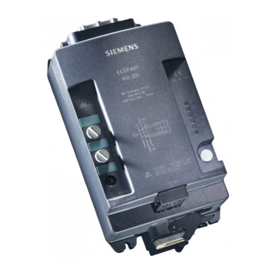
Motor Starters: Overview What are ECOFAST Motor Starters? ECOFAST Motor Starters are part of the ECOFAST system, which unifies the connection technology of all ECOFAST components. ECOFAST Motor Starters are • available as reversing starters and soft starters • suitable for switching and protecting three-phase loads rated at 400 V AC up to 4 kW (mechanical switching) and up to 5.5 kW (soft starter) -
Page 14: Fieldbus Interfaces
Motor Starters: Overview 1.2.2 Fieldbus interfaces Depending on the device version, ECOFAST Motor Starters have the follo- wing fieldbus interfaces: PROFIBUS-DP PROFIBUS-DP interface with data terminal and data tee connector, optionally for copper cable or fiber-optic cable AS-Interface (AS-i) AS-i interface using insulation... -
Page 15: Product Overview
3RK1 303-6DS71-1AA0 3RK1 303-6DS71-1AA3 Shaded boxes: device function for this order number available Light-gray fields: Description in manual "ECOFAST Motor Starters High Feature" Order no. 3RK1 702-3AB18-1AA0 (German) Order no. 3RK1 702-3BB18-1AA0 (English) Gray fields: Description in this manual "ECOFAST Motor Starters"... -
Page 16: Table 1-2: Product Overview Of Motor Starters With As-Interface
3RK1 323-6DS71-1AA0 3RK1 323-6DS71-1AA3 Shaded boxes: device function for this order number available Light-gray fields: Description in manual "ECOFAST Motor Starters High Feature" Order no. 3RK1 702-3AB18-1AA0 (German) Order no. 3RK1 702-3BB18-1AA0 (English) Gray fields: Description in this manual "ECOFAST Motor Starters"... - Page 17 Motor Starters: Overview ECOFAST Motor Starters GWA 4NEB 950 0562-12...
-
Page 18: Installation Of Motor Starters
(motor plugged in with mounting plate). Section Subject Page Setting the address Setup with motor plugged in 2.2.1 Required components 2.2.2 Installation Setup with motor nearby 2.3.1 Required components 2.3.2 Installation ECOFAST Motor Starters GWA 4NEB 950 0562-12... -
Page 19: Setting The Address
Set the required address. After carrying out addressing, screw the screw cap back into the socket in order to obtain degree of protection IP 67. Table 2-2: Setting the address via the addressing socket ECOFAST Motor Starters GWA 4NEB 950 0562-12... -
Page 20: Setup With Motor Plugged In
24 V auxiliary voltage depending on length AUX PWR Cable end covers for sealing open 3RK1 901-1MN00 cable ends (1 set = 10 covers) Table 2-3: Components required for setting up with the motor plugged in ECOFAST Motor Starters GWA 4NEB 950 0562-12... -
Page 21: Installation
Plug in the power tee connector at the power terminal on the motor starter. Secure the connection with the locking device. Connect the power cables to the power tee connector. Secure the connections with the locking devices. Table 2-4: Installation: motor plugged in ECOFAST Motor Starters GWA 4NEB 950 0562-12... -
Page 22: Setup With Motor Nearby
24 V auxiliary voltage depending on length AUX PWR Cable end covers for sealing open 3RK1 901-1MN00 cable ends (1 set = 10 covers) Table 2-5: Components required for setting up with the motor nearby ECOFAST Motor Starters GWA 4NEB 950 0562-12... -
Page 23: Installation
Any required mounting position can be chosen. Drill 4 holes for screw attachment. Screw the motor starter down onto the flat surface. Table 2-6: Installation: motor nearby ECOFAST Motor Starters GWA 4NEB 950 0562-12... - Page 24 Plug in the power tee connector at the power terminal on the motor starter. Secure the connection with the locking device. Connect the power cables to the power tee connector. Secure the connections with the locking devices. Table 2-6: Installation: motor nearby (cont.) ECOFAST Motor Starters GWA 4NEB 950 0562-12...
- Page 25 Installation of Motor Starters ECOFAST Motor Starters GWA 4NEB 950 0562-12...
-
Page 26: Wiring And Interfaces
Pin assignment 3.4.2 Preparing power cables 3-10 Power tee connectors 3-12 Digital inputs 3-13 AS-i interface 3-14 3.7.1 Connection techniques 3-14 3.7.2 Behavior in the event of a power failure 3-15 Addressing socket 3-16 ECOFAST Motor Starters GWA 4NEB 950 0562-12... - Page 27 Ensure that the wiring is carried out carefully and correctly. Otherwise motor starters may be destroyed. There is potentially lethal danger! Caution Note that star jumpers are already wired in the motor starter. ECOFAST Motor Starters GWA 4NEB 950 0562-12...
-
Page 28: Power Cables Prefabricated At One End
Assignment Neutral N Phase L2 — — 24 V DC 0 V DC Phase L3 — — Phase L1 PE (yellow/green) Fig. 3-2: Power cables prefabricated at one end with Han Q8 pin ECOFAST Motor Starters GWA 4NEB 950 0562-12... -
Page 29: Fig. 3-3: Power Cables Prefabricated At One End With Han 10E Pin
Winding terminal W2 Winding terminal U2 Winding terminal V2 — Temperature sensor (terminal a) — Temperature sensor (terminal b) PE (yellow/green) Fig. 3-3: Power cables prefabricated at one end with Han 10E pin ECOFAST Motor Starters GWA 4NEB 950 0562-12... -
Page 30: Wiring Rules
9.0 ... 13.0 mm white 11.5 ... 15.5 mm Length of insulation to strip from cores 8 mm Length of insulation to strip from cable sheath 20 mm Table 3-1: Rules for wiring ECOFAST Motor Starters GWA 4NEB 950 0562-12... -
Page 31: Unused Connections
Close off unused connections with screw caps; this is the only way of ensu- ring degree of protection IP 65. Order number 3 RK1 902-0CJ00 (10 screw caps) or 3 RK1 902-0CK00 (1 screw cap). ECOFAST Motor Starters GWA 4NEB 950 0562-12... -
Page 32: Fig. 3-4: Pin Assignment For Motor Terminal
Winding terminal W1 Brake (reference potential) Brake Winding terminal W2 Winding terminal U2 Winding terminal V2 Temperature sensor (terminal a) Temperature sensor (terminal b) Earthing screw: PE Fig. 3-4: Pin assignment for motor terminal ECOFAST Motor Starters GWA 4NEB 950 0562-12... -
Page 33: Table 3-2: Preparing Connecting Leads With Han 10E
(PELV). The brake must not be fed from the power supply unit for the 24V auxiliary circuit (AUX PWR, black cable). ECOFAST Motor Starters GWA 4NEB 950 0562-12... -
Page 34: Pin Assignment
Motor starter Han Q8 pin Motor Assignment Neutral N Phase L2 – Brake 24 V DC (optional) Brake 0 V DC (optional) Phase L3 – Phase L1 Fig. 3-5: Pin assignment for power terminal ECOFAST Motor Starters GWA 4NEB 950 0562-12... -
Page 35: Table 3-3: Preparing Connecting Leads With Han Q8
• 2.5 mm : 3RK1 902-0CA00 • 2.5 mm : 3RK1 902-0CC00 • 4.0 mm : 3RK1 902-0CB00 • 4.0 mm : 3RK1 902-0CD00 Table 3-3: Preparing connecting leads with Han Q8 ECOFAST Motor Starters 3-10 GWA 4NEB 950 0562-12... -
Page 36: Fig. 3-6: Han Q8 Power Connector
Pull the cable back and screw the insert in place in the connector housing with the enclosed screws. Screw the heavy-gauge threaded joint tight. Table 3-4: Assembling and wiring power connectors ECOFAST Motor Starters GWA 4NEB 950 0562-12 3-11... -
Page 37: Fig. 3-7: Pin Assignment For Power Tee Connector
Han Q8 socket to motor starter Assignment Neutral N Phase L2 – Brake 24 V DC Brake 0 V DC Phase L3 – Phase L1 Fig. 3-7: Pin assignment for power tee connector ECOFAST Motor Starters 3-12 GWA 4NEB 950 0562-12... -
Page 38: Pin Assignment
You must acknowledge this fault with trip reset. Important! Do not use an external power supply because otherwise there will be a risk of short-circuits. ECOFAST Motor Starters GWA 4NEB 950 0562-12 3-13... -
Page 39: Fig. 3-9: As-I Interface
Fig. 3-9: AS-i interface Contacting The AS-i cables are contacted automatically using the insulation piercing method when the AS-i cover is screwed on. AS-i cover AUX PWR AS-i Fig. 3-10: Contacting the AS-i cables ECOFAST Motor Starters 3-14 GWA 4NEB 950 0562-12... - Page 40 • In the event of prolonged undervoltage or power failure > 20 ms the swit- ching elements and the brake output are disconnected. • When the supply is restored, the disconnection command and the associated signal bits and error bits are acknowledged automatically. ECOFAST Motor Starters GWA 4NEB 950 0562-12 3-15...
-
Page 41: Fig. 3-11: Addressing Socket
This is connected to the addressing socket with the connecting lead. IN.1/2 Addressing socket AS-i AUX PWR IN.2 STATE DEVICE Connecting lead Addressing socket Screw cap ADDR. Fig. 3-11: Addressing socket ECOFAST Motor Starters 3-16 GWA 4NEB 950 0562-12... -
Page 42: Commissioning And Diagnostics
Commissioning and diagnostics Section Subject Page Process data and process images Commissioning and starting Diagnostics through LED indicators Diagnostics with the addressing and diagnostic unit Behavior in the event of faults ECOFAST Motor Starters GWA 4NEB 950 0562-12... -
Page 43: Process Data And Process Images
[1]: Thermoclick [0]: PTC type A Behavior in the event of [1]: Trip overload - temperature sensor [0]: Warn Auto reset [1]: NO [0]: YES Table 4-1: Process data and process image, AS-Interface ECOFAST Motor Starters GWA 4NEB 950 0562-12... - Page 44 / general warning present, the self-test function is triggered. This results in overload tripping with "Warn/Trip", depending on the "Behavior in the event of overload - temperature sensor" parameter (PO-0.2) ECOFAST Motor Starters GWA 4NEB 950 0562-12...
-
Page 45: Commissioning And Starting
[0] –> [1]: ACTIVE [0], [1]: NOT ACTIVE Table 4-4: Testing the wiring from the motor starter to the motor Further information is provided in the operating instructions for the addressing and diagnostic unit. ECOFAST Motor Starters GWA 4NEB 950 0562-12... -
Page 46: Fig. 4-1: Starting The Motor Starter
Does the configuration data match the actual setup? Inputs and outputs Remedy: match enabled; configuration data to setup or data exchange is possible vice versa Ready for operation Fig. 4-1: Starting the motor starter ECOFAST Motor Starters GWA 4NEB 950 0562-12... -
Page 47: Diagnostics Through Led Indicators
Digital input 1: 24 V DC present Digital input 1: 24 V DC not present IN.2 green Digital input 2: 24 V DC present Digital input 2: 24 VDC not present Table 4-5: Diagnostics through LED indicators ECOFAST Motor Starters GWA 4NEB 950 0562-12... -
Page 48: Diagnostics With The Addressing And Diagnostic Unit
Switching element defective Tripping Power OFF STATE Fault is automatically acknowledged after elimination of the cause of the fault (not to be confused with auto reset!) Table 4-6: Possible faults and fault handling ECOFAST Motor Starters GWA 4NEB 950 0562-12... - Page 49 / general warning present, the self-test function is triggered. This results in overload tripping with "Warn/Trip", depending on the "Behavior in the event of overload - temperature sensor" parameter (PO-0.2). ECOFAST Motor Starters GWA 4NEB 950 0562-12...
-
Page 50: Device Functions
Device functions Section Subject Page Temperature sensor Reversing starter control function Mechanical braking 6.14 Electronic/mechanical switching technology ECOFAST Motor Starters GWA 4NEB 950 0562-12... -
Page 51: Temperature Sensor
(auto reset). Possible fault causes: – Temperature sensor overload – Temperature sensor wire break – Temperature sensor short-circuit Setting range with parameter PO-0.3: • Auto reset [1]: NO [0]: YES ECOFAST Motor Starters GWA 4NEB 950 0562-12... -
Page 52: Reversing Starter Control Function
DO-0.0 [1]: ON [0]: OFF • Motor CCW DO-0.1 [1]: ON [0]: OFF The reversing starter control function returns the following signal to input DI-0.1: • Motor on DI-0.1 [1]: YES [0]: NO ECOFAST Motor Starters GWA 4NEB 950 0562-12... -
Page 53: Mechanical Braking
Braking Temperature sensor magnet (terminal a) Temperature sensor (terminal b) Fig. 5-1: Typical circuit for mechanical braking Control output The brake is controlled with output DO-0.2: • Brake DO-0.2 [1]: ON [0]: OFF ECOFAST Motor Starters GWA 4NEB 950 0562-12... -
Page 54: Electronic/Mechanical Switching Technology
The "Switching technology" device function returns the "General fault" signal in response to the following causes: • Switching element defective (e.g. contactor contact welded, power semicon- ductor failed) • Switching element overload (e.g. semiconductor too hot, only applicable to soft starters) ECOFAST Motor Starters GWA 4NEB 950 0562-12... - Page 55 Device functions ECOFAST Motor Starters GWA 4NEB 950 0562-12...
-
Page 56: Technical Data
Technical data Section Subject Page General technical data Auxiliary power Digital inputs Main power A.4.1 Mechanical switching A.4.2 Brake output 400 V AC ECOFAST Motor Starters GWA 4NEB 950 0562-12... -
Page 57: General Technical Data
2 kV / 5 kHz supply voltage IEC 1000-4-4 severity 3 1 kV / 5 kHz data lines 2 kV / 5 kHz process lines Emitted interference Limit value class A EN 55011 ECOFAST Motor Starters GWA 4NEB 950 0562-12... -
Page 58: Auxiliary Power
500 V DC between the auxiliary voltages and PE Digital inputs Input voltage 20.4V DC to 28.8V DC Current consumption Typically 7 mA per input Sensor supply Max. 200 mA (from AS-i. Sensor supply is short-circuit-proof) ECOFAST Motor Starters GWA 4NEB 950 0562-12... -
Page 59: Main Power
IEC 60947-1 voltage Safety separation 300 V AC between auxiliary and main power Frequency 50/60 Hz ON duration 100% Short-circuit protection Fusible link am-16 A/500VAC / Ik=120kA Utilization category Device destroyed after short- circuit ECOFAST Motor Starters GWA 4NEB 950 0562-12... -
Page 60: Mechanical Switching
(= 50 switching operations /h 35 s and ON duration = 50%) 36 s 36 s Waiting time The time between the switch-off command and the next switch-on command Motor CCW Motor CW 300 ms ECOFAST Motor Starters GWA 4NEB 950 0562-12... -
Page 61: Brake Output 400 V Ac
Technical data A.4.2 Brake output 400 V AC Voltage range 100 V AC to 460 V AC Current carrying capacity AC 15: 500 mA Short-circuit protection Fusible link am 1 A/500VAC ECOFAST Motor Starters GWA 4NEB 950 0562-12... -
Page 62: Dimension Drawings
Dimension drawings Section Subject Page Motor Sarter ECOFAST Motor Starters GWA 4NEB 950 0562-12... -
Page 63: Motor Starter
Motor Starter Fig. 2-1: Motor starter dimension drawing ECOFAST Motor Starters GWA 4NEB 950 0562-12... -
Page 64: Order Numbers
Motor Starters (Reversing starters) Motor Connection Cables and Power Cables Power & Control Modules (Infeed Modules) Hybrid Fieldbus Cables AS-Interface Shaped Cable Hybrid Fieldbus Interfaces Connectors Project engineering software and Documentation Tools, Connector Sets, Configuration C-10 ECOFAST Motor Starters GWA 4NEB 950 0562-12... -
Page 65: Motor Starters (Reversing Starters
Temperature AS-Interface 3RK1 323-2AS51- 1AA0 Sensor / 400 V AC AS-Interface 3RK1 323-2AS51- 1AA3 Mechanical ECOFAST Motor Starters High Feature 0.3 A - 9 A (4 kW) Temperatur- PROFIBUS-DP 3RK1 303-2AS51- 1AA0 Sensor / 400 V AC PROFIBUS-DP 3RK1 303-2AS51- 1AA3 Mechanical 0.3 A - 3 A (1.1 kW) -
Page 66: Motor Connection Cables And Power Cables
- 5 x 4.0 mm 10.0 m 3RK1 911-0BB40 - 5 x 4.0 mm > 10 m to < 15 m, any length 3RK1 911-0CB50 Table C-2: Order numbers for Motor Connection Cables and Power Cables ECOFAST Motor Starters GWA 4NEB 950 0562-12... - Page 67 - 7 x 2.5 mm 10.0 m 3RK1 911-0BD40 - 7 x 2.5 mm > 10 m to < 15 m, any length 3RK1 911-0CD50 Table C-2: Order numbers for Motor Connection Cables and Power Cables ECOFAST Motor Starters GWA 4NEB 950 0562-12...
-
Page 68: Power & Control Modules (Infeed Modules
Rotary actuator with main switch functions SIGUARD contactor safety combination Autostart Dimensions (W x H x D) in mm: 400 x 650 x 248 Table C-3: Order numbers for Power & Control Modules ( Infeed Modules) ECOFAST Motor Starters GWA 4NEB 950 0562-12... -
Page 69: Hybrid Fieldbus Cables
Order numbers Order numbers Hybrid Fieldbus Cables Description Order No. PROFIBUS ECOFAST Hybrid Cable – fiber-optic Trailing cable (PUR casing) with two plastic FO conductors for PROFIBUS-DP and four copper cores with 1,5 mm (DESINA-compatible) Pre-assembled with two ECOFAST connectors - 1.5 m... -
Page 70: As-Interface Shaped Cable
Hybrid Fieldbus Interface Copper-LWL/ FO, Pin / Socket for looping through 3RK1 911-1AD32 Hybrid Fieldbus Interface Copper / Copper, Socket / Socket incoming supply 3RK1 911-1AE22 (active) Table C-6: Order numbers for Hybrid Fieldbus Interfaces ECOFAST Motor Starters GWA 4NEB 950 0562-12... -
Page 71: Connectors
Data Tee Connector Cu 3RK1 911-2AG00 Data Tee Connector FO 3RK1 911-2AH00 ECOFAST Bus Terminating Connector for PROFIBUS-DP 3RK1 911-2AK00 PROFIBUS FO plug connector with 2x plastic FO and 4x copper conductors 1.5 mm Contact type: POF, Han D for 24 V... -
Page 72: Project Engineering Software And Documentation
(view interactive catalog CA01) – CD-ROM drive • STEP7 object manager – for integrating the ECOFAST starter as an S7 slave in SIMATIC S7 – for calling Switch ES from STEP7 System requirements: – SIMATIC: S7, M7, C7, PCS7 –... -
Page 73: Tools, Connector Sets, Configuration
3RK1 911-4AA0 Test connector set 3RK1 911-4AB0 Cable end covers for AS-Interface Shaped Cable 3RK1 901-1MN00 Addressing and diagnostic unit for AS-i 3RK1 904-2AB00 Table C-9: Order numbers for Tools, Connector Sets, Configuration ECOFAST Motor Starters C-10 GWA 4NEB 950 0562-12... -
Page 74: Index
Starting the motor starter Electronic switching technology Temperature sensor Faults Temperature sensor leads Fieldbus interfaces Testing the wiring Thermoclick Trip reset 3-3, 3-8 General technical data Han Q8 power connectors Wiring rules LED indicators ECOFAST Motor Starters Index-1 GWA 4NEB 950 0562-12... - Page 75 ECOFAST Motor Starter Index-2 GWA 4NEB 950 0562-12...
-
Page 76: Correction Page
Address Fax: 09621 / 80-3337 Telephone ECOFAST Motor Starters system manual Have you found any typographical errors while reading this manual? Please use this form to tell us about them. We would also welcome any ideas and suggestions you may have. - Page 77 Correction page ECOFAST Motor Starters GWA 4NEB 950 0562 12...