Sony NW-WM1A Service Manual
Digital music player
Hide thumbs
Also See for NW-WM1A:
- Help manual (144 pages) ,
- Manual (3 pages) ,
- Instruction manual (2 pages)
Table of Contents
Advertisement
SERVICE MANUAL
Ver. 1.0 2016.10
Note:
Be sure to keep your PC used
for service and checking of this
unit always updated with the
latest version of your anti-virus
software.
In case a virus affected unit was
found during service, contact
your Service Headquarters.
• Headphones and microSD card are not supplied with this unit.
CAUTION
Danger of explosion if battery is incorrectly replaced.
Replace only with the same or equivalent type.
Display
Size/resolution
4.0-inch (10.2 cm) / FWVGA (854 × 480 Pixels)
TFT color display with white LED-backlight
Panel type
Capacitive touch screen
Interface
USB
Hi-Speed USB (USB 2.0 compliant)
Headphone
Stereo mini-jack, Balanced standard-jack
WM-PORT
WM-PORT (multiple connecting terminal): 22 pins
microSD
External memory
microSDHC
microSDXC
Bluetooth
Bluetooth Specifications
Communication system
Bluetooth Specification Version 4.2
Frequency band
2.4 GHz band (2.4000 GHz - 2.4835 GHz)
Modulation method
FHSS
A2DP (Advanced Audio Distribution Profile)
Compatible Bluetooth profiles (*1)
AVRCP (Audio Video Remote Control Profile)
Supported Codec (*2)
SBC (*3), LDAC
*1
Bluetooth profiles are standardized according to the purpose of the Bluetooth device.
*2
Codec indicates the audio signal compression and conversion format.
*3
SBC stands for Subband Codec.
9-896-325-01
2016J33-1
Sony Video & Sound Products Inc.
©
2016.10
NW-WM1A/WM1Z
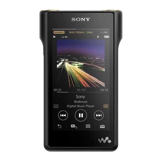
Photo: NW-WM1A
SPECIFICATIONS
Output (headphones)
Frequency response
Frequency
20 Hz to 40,000 Hz
(when playing data file, single signal measurement)
General
Built-in Rechargeable lithium-ion Battery
Power Source
USB power (from a computer via a USB connector of the player)
USB-based charging
Charging Time
Approx. 7 hours
Operating temperature
5°C to 35°C (41 ºF to 95 ºF)
w/h/d, projecting parts not included
Approx. 65.3 mm × 123.4 mm × 19.9 mm
(2.58 inches × 4.86 inches × 0.79 inches)
Dimensions (Walkman)
w/h/d
Approx. 72.9 mm × 124.2 mm × 19.9 mm
(2.87 inches × 4.89 inches × 0.79 inches)
NW-WM1Z
Approx. 455 g (16.1 oz)
Mass (Walkman)
NW-WM1A
Approx. 267 g (9.5 oz)
w/h/d, projecting parts not included
Dimensions (Leather case)
Approx. 81 mm × 132 mm × 29 mm
(NW-WM1Z only)
(31.9 inches × 52.0 inches × 11.5 inches)
Canadian Model
Australian Model
Photo: NW-WM1Z
Capacity
NW-WM1Z
NW-WM1A
Actual available memory for other contents (*1)
NW-WM1Z
NW-WM1A
*1
Available capacity may vary. A portion of the memory is used for data management functions.
DIGITAL MUSIC PLAYER
US Model
NW-WM1Z
AEP Model
UK Model
E Model
Chinese Model
Tourist Model
NW-WM1A/WM1Z
256 GB
128 GB
Approx. 230.60 GB = 247,612,538,880 byte
Approx. 114.15 GB = 122,573,127,680 byte
Advertisement
Table of Contents

Related Manuals for Sony NW-WM1A


Summary of Contents for Sony NW-WM1A
- Page 1 Dimensions (Leather case) Approx. 81 mm × 132 mm × 29 mm SBC stands for Subband Codec. (NW-WM1Z only) (31.9 inches × 52.0 inches × 11.5 inches) DIGITAL MUSIC PLAYER 9-896-325-01 2016J33-1 Sony Video & Sound Products Inc. © 2016.10...
- Page 2 31 hours Bit depth: 16, 24, 32 bit • SensMe and the SensMe logo are trademarks or registered trademarks of Sony Sampling frequency: 8, 11.025, 12, 16, 22.05, 24, 32, 44.1, 48, 88.2, 96, 176.4, 192, 352.8, 384 kHz Mobile Communications AB.
-
Page 3: Table Of Contents
NW-WM1A/WM1Z TABLE OF CONTENTS SERVICING NOTES ..........DISASSEMBLY 2-1. Disassembly Flow ............14 2-2. Rear Cover Assy ............. 15 2-3. Rear Support (Lower), Rear Support Assy (Upper) ..15 2-4. Battery Assy Block-1 ............16 2-5. Battery Assy Block-2 ............17 2-6. -
Page 4: Servicing Notes
WALKMAN main unit. Refer to the following table. Wrap by the tape etc. and insulate the end of battery Note 2: The NW-WM1A has been engraved to the main unit. wire. The NW-WM1Z has been affi xed label to the main unit. - Page 5 NW-WM1A/WM1Z ABOUT WORKING OF THE BOARD REPLACING Procedure: When replaced the MAIN board, be sure to refer to each settings/ 1. On PC (personal computer), unzip the advance prepared each checks on the following and perform. settings/checking tools. 2. Copy the unzip folder to root directory of C drive on PC (per- 1.
- Page 6 NW-WM1A/WM1Z Procedure: 8. Check that the following fi gure message has been displayed, and input “y”, and press the Enter key. 1. Connect the WALKMAN main unit to PC (personal computer) by the USB cable (WM-PORT). (Using 2-byte characters, it may not be displayed correctly)
- Page 7 (“f:” is drive letter of checked at step 2) tination/model settings, be sure to perform the initial settings. Used folder name (tool): C:\NWXXXX_Color_Init_Setting_V1.00\BLACK>updating.bat f: For NW-WM1A : NWWM1A_Color_Init_Setting_V1.00 For NW-WM1Z : NWWM1Z_Color_Init_Setting_V1.00 “WM1A” or “WM1Z” Input Note 1: “BLACK” folder exist in folder for the NW-WM1Z, but this is no problem to use it.
- Page 8 NW-WM1A/WM1Z 2-3. Model information check 8. It will appear the following fi gure results. (Displayed characters/values in the following fi gure are ex- It can check the settings information. ample) Be sure to that the correct settings have been performed.
- Page 9 NW-WM1A/WM1Z 2-4. Pre-installed contents settings 6. Check into the [I agree] box on “SoftwareUpdateTool”, and click the [Next] button. Write the pre-installed contents. Note 3: The language displayed in “SoftwareUpdateTool” changes with Perform after each checks/settings. linguistic environment of PC.
- Page 10 NW-WM1A/WM1Z 10. Open the WALKMAN storage. Check disappear copied “opt3” 14. After the WALKMAN is rebooted, language/date/time of ini- folder in step 4 and the “_opt3” folder has been created. tial setup wizard to complete, and connect the WALKMAN Note 5: If the “_opt3” folder does not created, start over from step 1.
- Page 11 NW-WM1A/WM1Z ABOUT THE REPAIRING OF BOARD 2. If the NFC connection is normal, the pop-up menu shown in the fi gure below is displayed on the WALKMAN screen. When boards installed in this unit are defective, it is replaced by Note 3: If there is a problem with the connection, you are not presented the board.
- Page 12 NW-WM1A/WM1Z NFC function checking fl ow chart: Disassemble until you see the built- in NFC antenna of main unit. Note: That the main unit is state to operate. The NFC antenna is properly connected to the connector on the The NFC antenna is properly...
- Page 13 NW-WM1A/WM1Z VARIOUS INITIALIZATION METHOD • Setting method It can perform the various initialization from the settings menu of Library screen the WALKMAN main unit. Refer to the following, please run the appropriate initialization. • Various initialization item This operation resets all setting parameters to the default settings.
-
Page 14: Disassembly
NW-WM1A/WM1Z SECTION 2 DISASSEMBLY • This set can be disassembled in the order shown below. 2-1. DISASSEMBLY FLOW 2-2. REAR COVER ASSY (Page 15) 2-3. REAR SUPPORT (LOWER), REAR SUPPORT ASSY (UPPER) (Page 15) 2-4. BATTERY ASSY BLOCK-1 2-8. ANTENNA (WIFI/BT) (ANT1) -
Page 15: Rear Cover Assy
NW-WM1A/WM1Z Note: Follow the disassembly procedure in the numerical order given. 2-2. REAR COVER ASSY adhesive sheet (rear) When installing the rear cover assy, align and attach in the order below. 2 Push. 2 rear cover assy 4 Push. top side 1 Push. -
Page 16: Battery Assy Block-1
NW-WM1A/WM1Z 2-4. BATTERY ASSY BLOCK-1 • Continued on 2-5 (page 17). CN7052 antenna (NFC) CN7052 side 2 Unlock the connector side bottom guide line sheet (NFC FPC) (CN7052). side 1 sheet (NFC FPC) 3 Draw the antenna (NFC) out of the connector. -
Page 17: Battery Assy Block-2
NW-WM1A/WM1Z 2-5. BATTERY ASSY BLOCK-2 8 battery assy block Note 1: If the battery assy block is installed, arrange the battery wire [black] as shown 2 sheet in the figure below. (battery solder) sheet battery wire [black] (battery solder) bottom... -
Page 18: Lithium Ion Storage Battery (Bat1), Battery Case Assy (Nfc1)
NW-WM1A/WM1Z 2-6. LITHIUM ION STORAGE BATTERY (BAT1), BATTERY CASE ASSY (NFC1) bottom side lithium ion storage battery PWB cushion bottom 16.5 ± 0.5 mm side PWB cushion guide 21.9 mm 18 mm line lithium ion storage battery multi cushion 2 PWB cushion... -
Page 19: Cover Sheet (Pwb)
NW-WM1A/WM1Z 2-7. COVER SHEET (PWB) guide line Note: When soldering, be careful so that bottom side 1 Remove the solder. the soldering iron does not touch the cabinet block. 2 cover sheet MAIN board soldering iron (PWB) cabinet bottom cover sheet (PWB) -
Page 20: Cable Holder
NW-WM1A/WM1Z 2-9. CABLE HOLDER top side sheet (wire detector) 1 sheet (wire detector) 2 stereo mini jack cable connector (CN7022) sheet (wire detector) top side front side bottom side cushion cushion (CONN support) (CONN support) 5 cushion (CONN support) 4 screw (NDS-EL) (M1.4... -
Page 21: Battery Spacer Sheet, Battery Spacer
NW-WM1A/WM1Z 2-10. BATTERY SPACER SHEET, BATTERY SPACER battery spacer sheet bottom side Attach in order from 1 to 4. Align the hole. 1 Affix the adhesive sheet (LG card). battery spacer bottom side 1 battery spacer sheet HOLD-NFC FPC bottom side 3 Peel the HOLD-NFC FPC off of the adhesive sheet (LG card). -
Page 22: Jack Ring (S), Jack Hook (S) (Stereo Mini Side)
NW-WM1A/WM1Z 2-11. JACK RING (S), JACK HOOK (S) (STEREO MINI SIDE) ow o i 1 Align the jack hook (S) with the hole 4 Rotate the jack hook (S) shape of the cabinet and install. 3 Lock the claw. counter-clockwise to remove the lock. -
Page 23: Jack Ring (B), Jack Hook (B) (Balanced Standard Side)
NW-WM1A/WM1Z 2-12. JACK RING (B), JACK HOOK (B) (BALANCED STANDARD SIDE) 3 Lock the two 1 Align the jack hook (B) with the hole claws. shape of the cabinet and install. 4 Rotate the jack hook (B) counter-clockwise to remove the lock. -
Page 24: Main Board Block-1
NW-WM1A/WM1Z 2-13. MAIN BOARD BLOCK-1 • Continued on 2-14 (page 25). escutcheon escutcheon stopper guide line stopper bottom side 6 Remove the solder. 1 screw (NDS-EL) WM1A: [black] 5 Remove the solder. (M1.4 WM1Z: [white] WM1A: [white] WM1Z: [natural] 7 Remove the solder. -
Page 25: Main Board Block-2
NW-WM1A/WM1Z 2-14. MAIN BOARD BLOCK-2 7 MAIN board block 3 two screws (NDS-EL) Note: When installing the MAIN board, (M1.4 align the hole and groove on the board WM-PORT 5 Draw the HP SE assy block out of with the two ribs on the cabinet block. -
Page 26: Hp Se Assy Block (Stereo Mini Side), Main Board
NW-WM1A/WM1Z 2-15. HP SE ASSY BLOCK (STEREO MINI SIDE), MAIN BOARD Note 1: When the MAIN board is replaced, refer to “ABOUT WORK- ING OF THE BOARD REPLACING” on page 5. 1 Remove the solder. 2 Remove the solder. WM1A: [white]... -
Page 27: Hp Se Assy (Hpj1) (Stereo Mini Side)
NW-WM1A/WM1Z 2-16. HP SE ASSY (HPJ1) (STEREO MINI SIDE) Note: Some wire connections have been removed from the picture in the fi gure to make the position of the sheet (strap) easier to recognize. 4 HP SE assy (HPJ1) 3 sheet... -
Page 28: Hp Btl Assy (Hpj2) (Balanced Standard Side)
NW-WM1A/WM1Z 2-18. HP BTL ASSY (HPJ2) (BALANCED STANDARD SIDE) (NW-WM1Z) 3 HP BTL assy 2 O ring (band) (HPJ2) 1 sheet (strap) 1 sheet (strap) (NW-WM1A) (NW-WM1Z) no wire no wire sheet (strap) short wire sheet (strap) wire [white] [natural]... -
Page 29: Hold-Nfc Fpc Assy (Fpc1)
NW-WM1A/WM1Z 2-19. HOLD-NFC FPC ASSY (FPC1) relay copper sheet top side guide line 1 relay copper sheet 3 screw (SG) (M1.4) knob assy 3 screw (SG) slide switch 4 knob assy (M1.4) 5 HOLD-NFC FPC assy (FPC1) 1 Align the knob assy... -
Page 30: Pwb Chassis
NW-WM1A/WM1Z 2-20. PWB CHASSIS 2 light guide (card) block guide line bottom adhesive sheet (LG card) side 4 light guide holder block Note: When installing the 1 Peel the light guide (card) block light guide holder off of the light guide holder. -
Page 31: Strap Holder Assy, Card Lid Assy
NW-WM1A/WM1Z 2-21. STRAP HOLDER ASSY, CARD LID ASSY Note: Start removing from either the strap holder assy or card lid assy. rear side bottom top side 1 screw (NDS-EL) (M1.4 SD card mark strap holder card lid assy block front side... -
Page 32: Lcd Assy (Lcd1), Cabinet Assy
NW-WM1A/WM1Z 2-23. LCD ASSY (LCD1), CABINET ASSY 1 two screws (NDS-EL) (M1.4 slit bottom side 2 Push out the LCD assy block from the slit in the direction of the arrow using a flat-tipped tool, etc. flat-tipped tool, etc. front side... -
Page 33: Test Mode
1. ADVANCE PREPARATION Before working, prepare the following tools etc. • Tool for test mode: For NW-WM1A : NWWM1A_TestMode_V1.00 For NW-WM1Z : NWWM1Z_TestMode_V1.00 • USB cable (WM-PORT) • PC (personal computer (OS: Windows 7 or later)) Note 1: Check the method of obtaining the test mode tool to the each ser- vice headquarters. - Page 34 NW-WM1A/WM1Z 12. The WALKMAN main unit reboots and the test mode menu is 4. CONFIGURATION OF THE TEST MODE displayed on the WALKMAN main unit. Major item switching: Major item [–] keys Screen display Diagnosis APP [u] key or [.] key or [ver X.XX.XX]...
- Page 35 NW-WM1A/WM1Z 5-1-2. Consumption current (audio playback) check 6. Sleep is released by pressing any key (button) of WALKMAN main unit. (Current check) It can be check the consumption current (audio playback) in the Screen display state where audio signal is outputted of the “Sampling rate: 44.1 kHz/Frequency: 1 kHz (L/R-ch)/Bit rate: 16 bit”.
- Page 36 NW-WM1A/WM1Z 5-1-5. Battery voltage detection check (Battery voltage) 5-2. Audio (Audio) It can be check the battery voltage. Screen display Diagnosis APP Procedure: [ver X.XX.XX] 1. Enter the test mode. Audio (Refer to “2. SETTING THE TEST MODE” on page 33) Output sound check 2.
- Page 37 NW-WM1A/WM1Z 5-2-2. S/N check (S/N check) 5-2-4. Frequency response check 2 (Frequency check2) It can be output the “Sampling rate: 44.1 kHz/Frequency: 0 kHz It can be output the “Sampling rate: 44.1 kHz/Frequency: 20 kHz (L/R-ch)/Bit rate: 16 bit” audio signal for the S/N check.
- Page 38 NW-WM1A/WM1Z 5-2-6. CH separation (R-ch) check (Separation-R check) 5-2-8. Normalizer check (Normalizer) It can be output the “Sampling rate: 44.1 kHz/Frequency: 1 kHz It can be output the “Sampling rate: 44.1 kHz/Frequency: 1 kHz (R-ch)/Bit rate: 16 bit” audio signal for the separation (R-ch) (L/R-ch)/Bit rate: 16 bit”...
- Page 39 NW-WM1A/WM1Z 5-2-10. Playback user fi le 1 (Play user fi le-1) 5-3. Video (Video) Note: Not used for the servicing. Screen display 5-2-11. Playback user fi le 2 (Play user fi le-2) Diagnosis APP [ver X.XX.XX] Note: Not used for the servicing.
- Page 40 NW-WM1A/WM1Z 5-4. Noise canceller (Noise cancel) 5-8-3. NFC PRBS test (PRBS test) Note: This major item is not used in this model. Note: Not used for the servicing. 5-5. Direct recording (Direct Rec) 5-8-4. Read register (Read register) Note: This major item is not used for the servicing.
- Page 41 NW-WM1A/WM1Z 5-10. Touch panel (Touch screen) 5-10-2. Cross check (Cross check) It can be displayed the black line of touch locus of touch panel, and Screen display change the line dot. Diagnosis APP Note: It can not operate in a state in which the WALKMAN main unit was [ver X.XX.XX]...
- Page 42 NW-WM1A/WM1Z 5-10-3. Tap check (Tap check) 5-11. Key (Key) It can be displayed the black points of tap locus of touch panel, and Screen display check the tap status. Note: It can not operate in a state in which the WALKMAN main unit was Diagnosis APP [ver X.XX.XX]...
- Page 43 NW-WM1A/WM1Z 5-11-2. Key press count check (Press count check) 5-15-2. Destination setting (Set destination) Note: Not used for the servicing. Note: Not used for the servicing. If you have entered this mode by mistake, press the [ u ] key in a state in which slide the [HOLD] switch in the direction of on, return 5-15-3.
- Page 44 NW-WM1A/WM1Z 5-15-6. NAND information check (NAND check) 5-15-8. Color variation check (Color variation) It can be check the information of NAND fl ash memory (eMMC). It can be check the information of the WALKMAN main unit body color. Procedure: 1. Enter the test mode.
- Page 45 NW-WM1A/WM1Z 5-15-10. Auto sleep setting (Auto sleep) 5-15-14. MSC connection control (MSC control) It can be setting the information of time-out timer setting of until It can be switched status of the MSC connection/disconnection. the sleep state. Procedure: Procedure: 1. Enter the test mode.
- Page 46 NW-WM1A/WM1Z 5-16. Shutdown (Shutdown) 5-16-2. Power off (test mode release) (PowerOFF (normal)) Screen display It can be the shutdown, releasing the test mode status. Diagnosis APP [ver X.XX.XX] Procedure: Shutdown 1. Enter the test mode. PowerOFF (diag) (Refer to “2. SETTING THE TEST MODE” on page 33) PowerOFF (normal) 2.
- Page 47 NW-WM1A/WM1Z 5-16-4. Reboot (test mode release) 5-17. Log (Log) (Reboot (normal)) Screen display It can be the reboot, releasing the test mode status. Diagnosis APP [ver X.XX.XX] Procedure: 1. Enter the test mode. Initialize log (Refer to “2. SETTING THE TEST MODE” on page 33) Add log 2.
- Page 48 NW-WM1A/WM1Z 5-17-4. Copy log data (Copy log) It can be copied log information recorded to NVP to the under root directory of the WALKMAN main unit storage. Note 1: It can not operate in a state in which the WALKMAN main unit was MSC connection.
-
Page 49: Exploded Views
NW-WM1A/WM1Z SECTION 4 EXPLODED VIEWS Note: • -XX and -X mean standardized parts, so • The mechanical parts with no reference they may have some difference from the number in the exploded views are not sup- original one. plied. • Items marked “*” are not stocked since •... -
Page 50: Battery Section
NW-WM1A/WM1Z 4-2. BATTERY SECTION top side front side ANT1 MAIN board section BAT1 bottom side NFC1 rear side Note 1: It cannot reuse, when the lithium ion storage battery (Ref. No. Note 2: When wire of the lithium ion storage battery (Ref. No. BAT1) BAT1) is removed from battery adhesive sheet. -
Page 51: Main Board Section
NW-WM1A/WM1Z 4-3. MAIN BOARD SECTION top side HPJ1 (WM1Z) front side chassis section bottom side rear side Note: When the complete MAIN board (Ref. No. 107) is replaced, re- fer to “ABOUT WORKING OF THE BOARD REPLACING” on page 5. -
Page 52: Chassis Section
NW-WM1A/WM1Z 4-4. CHASSIS SECTION top side 171 171 HPJ2 (WM1Z) LCD section front side FPC1 rear side bottom side Ref. No. Part No. Description Remark Ref. No. Part No. Description Remark 4-590-451-01 GUIDE (CARD), LIGHT 4-590-456-11 ESCUTCHEON (CARD) (WM1Z) 4-593-947-01... -
Page 53: Lcd Section
NW-WM1A/WM1Z 4-5. LCD SECTION LCD1 top side front side FPC2 not supplied (WM1Z) rear side bottom side Ref. No. Part No. Description Remark Ref. No. Part No. Description Remark 4-685-083-01 SCREW (SG) M1.4 X-2594-203-1 SVX CABINET ASSY (H) 4-573-907-11 SCREW (NDS-EL) M1.4 (L = 3 mm) -
Page 54: Accessories
NW-WM1A/WM1Z SECTION 5 ACCESSORIES Ref. No. Part No. Description Remark 4-593-853-11 STARTUP GUIDE (WM1A) 4-593-853-21 STARTUP GUIDE (WM1Z) 4-593-854-11 MANUAL, INSTRUCTION (ENGLISH, FRENCH, GERMAN, SPANISH, ITALIAN, GREEK, TURKISH, DUTCH, POLISH) (AEP, UK) 4-593-854-21 MANUAL, INSTRUCTION (ENGLISH, FRENCH, SPANISH) (US, CND) - Page 55 NW-WM1A/WM1Z MEMO...
- Page 56 NW-WM1A/WM1Z REVISION HISTORY Ver. Date Description of Revision 2016.10...