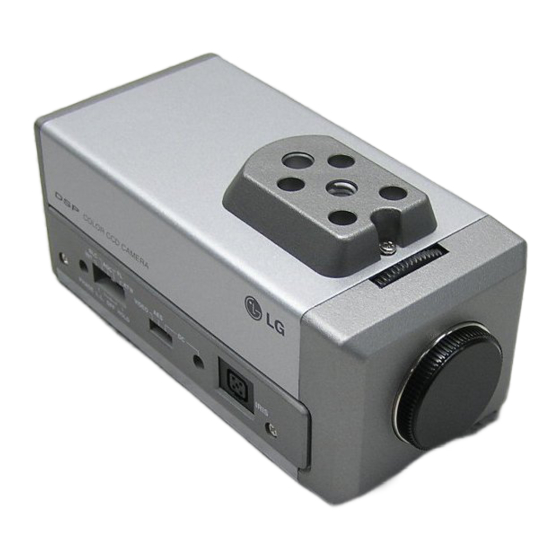
LG LVC-S60HM Operating Instructions Manual
Hide thumbs
Also See for LVC-S60HM:
- Operating instructions manual (12 pages) ,
- Operating instructions manual (24 pages)

Related Manuals for LG LVC-S60HM


Summary of Contents for LG LVC-S60HM
- Page 1 Operating Instructions LVC-S60HM LVC-S60HP LVC-S60NM LVC-S60NP Before installing and using the camera, please read these instructions thoroughly and retain them for later reference.
- Page 2 Warning CAUTION To prevent fire or shock hazard, do not expose the unit to rain or moisture. RISK OF ELECTRIC SHOCK DO NOT OPEN To avoid electrical shock, do not open the cabinet Refer servicing to qualified personnel only. Wiring methods shall be in accordance with the National Electric Code, CAUTION TO REDUCE THE RISK OF ELECTRIC SHOCK, ANSI/NFPA 70.
-
Page 3: Table Of Contents
Contents Features ..........................3 Cautions for Safe Operation ......................4 Operating Controls and Their Functions ................5-6 Connections .........................7-8 Back Focus Adjustment ......................9 Installation of Camera......................10 Specifications.........................11 FEATURES This color video camera is designed for use Maintence of the unit • Remove dust or dirt on the surface of the in monitoring system. -
Page 4: Cautions For Safe Operation
Cautions for Safe Operation Power Supply They must be operated with a AC 24V class 2 Operating and storage location power supply and DC12V alternatively. Avoid viewing a very bright object (such as light fittings) during an extended period. Avoid * Notes: Be careful of AC frequency when the operating or storing the unit in the following camera is operated with Line lock mode. -
Page 5: Operating Controls And Their Functions
OPERATING CONTROLS AND THEIR FUNCTIONS DC 12V VIDEO VIDEO IRIS POWER PHASE CLASS 2 ONLY AC 24V~ 10 12 11 Pin assignment of auto iris lens connector Pin No. DC iris Video iris Damping - Vcc (+9V) Damping + Not used Drive + Video Drive -... - Page 6 OPERATING CONTROLS AND THEIR FUNCTIONS The Adjustment method of Line Lock Phase ➀ ② When using a camera switcher to connect 2 cameras or more to one monitor, there may be a vertical roll of the images when switched. In such a case, refer to the below.
-
Page 7: Connections
CONNECTIONS Power Connection DC 12V LVC-S60 (DC12V/AC24V Compatible) 1. DC 12V Power Supply Remove the insulation on the power cable as illustrated and connect the power cord to the AC/DC compatible terminals on rear panel of the camera. Note : You don't need to be cautious of the polarity of positive and negative. - Page 8 Lens Mounting Remove the CCD cover. Then attach the CS mount lens to the camera. Please refer to the drawing on the left. C Mount Lens: You have to use the Adapter Ring Mount (not supplied). CAUTION Be cautious not to use Auto Iris Lens with over 30mA DC iris level is preset in the factory.
-
Page 9: Back Focus Adjustment
BACK FOCUS ADJUSTMENT If back focus has to be adjusted after mounting the lens, 1. Loosen the back focus lock screw(1) on top of the camera with a (+) screwdriver 2. Turn the back focus adjustment screw(2) on top of the camera with hands until the desired focus is reached. -
Page 10: Installation Of Camera
INSTALLATION OF CAMERA This camera is mounted with tripod which makes it possible to install from both of the bottom and the top of the unit as illustrated. -
Page 11: Specifications
Specifications Model LVC-S60HM LVC-S60HP LVC-S60NM LVC-S60NP Signal System NTSC NTSC Total/Effective Pixels 410K/380K 470K/440K 270K/250K 320K/290K Pick-Up Device 1/3 - Inch Interline Color CCD(Super HAD) Lens C / CS MOUNT (Adapter Ring Mount for C Lens: Optional) Iris Control DC / AES / VIDEO... - Page 12 P/NO.: 3834RS0072E...
- Page 13 LVC-S60HM LVC-S60HP LVC-S60NM LVC-S60NP...
- Page 14 ANSI/NFPA 70 U.S.A • • • • EEC DIRECTIVE 89/336/EEC 93/68/EEC 73/23/EEC...
- Page 15 ............................3 ........................4 ........................5-6 ............................7-8 ..........................9 ..........................10 ............................11 • • • Super HAD CCD ( • AC24V • • CS • AC 24V / DC 12V • DC12V...
- Page 16 AC 24V 2 DC12V • -10°C~50°C 0°C~45°C) AC24V(60Hz):S60HM/S60NM • AC24V(50Hz):S60HP/S60NP • • •...
- Page 17 Vcc (+9V)
- Page 18 -90° 90° PHASE...
- Page 19 DC 12V LVC-S60 (DC12V/AC24V 1. DC 12V AC/DC DC12V 2. AC 24V AC24V AC/DC 24V ±10% AC 24V~ VIDEO OUT...
- Page 20 30mA VIDEO VIDEO L.L. (SYNC) INT. (BLC) 10dB 30dB (AGC) 10dB ( (NTSC 1/100 PAL 1/120 (FL) HOLD (WB)
- Page 23 LVC-S60HM LVC-S60HP LVC-S60NM LVC-S60NP NTSC NTSC 410K/380K 470K/440K 270K/250K 320K/290K 1/3 - CCD (Super HAD) C / CS DC / AES / VIDEO 59.94Hz (VD) 50Hz (VD) 59.94Hz (VD) 50Hz (VD) 50 dB 2000Lux (5100°K) (1/3 0.4Lux (F1.0) 0.1Lux (F1.0)
- Page 24 P/NO.: 3834RS0072E...