
Related Manuals for Dell EMC PowerEdge C6400


Summary of Contents for Dell EMC PowerEdge C6400
- Page 1 Dell EMC PowerEdge C6400 Installation and Service Manual Regulatory Model: E43S Series Regulatory Type: E43S001...
- Page 2 A WARNING indicates a potential for property damage, personal injury, or death. © 2018 - 2019 Dell Inc. or its subsidiaries. All rights reserved. Dell, EMC, and other trademarks are trademarks of Dell Inc. or its subsidiaries. Other trademarks may be trademarks of their respective owners.
-
Page 3: Table Of Contents
Contents 1 Dell EMC PowerEdge C6400 overview.................... 6 Supported configurations..............................6 Front view of the Dell EMC PowerEdge C6400 enclosure....................8 Front view of the control panels............................8 Rear view of the enclosure with sleds..........................10 Sled to hard drive mapping..............................10 Expander zoning..................................11 Diagnostic indicators................................12... - Page 4 Removing a drive carrier..............................41 Installing a drive carrier..............................42 Removing the drive from the drive carrier......................... 43 Installing a drive into the drive carrier......................... 44 Power supply units................................45 Fault tolerant redundancy............................45 Removing a power supply unit.............................46 Installing a power supply unit............................47 System cover..................................
- Page 5 Installing the thermal sensor board..........................82 5 Getting help..........................84 Contacting Dell EMC................................84 Documentation feedback..............................84 Accessing system information by using QRL........................84 Quick Resource Locator for C6400 and C6420 systems..................85 Receiving automated support with SupportAssist ......................85 Recycling or End-of-Life service information........................85...
-
Page 6: Dell Emc Poweredge C6400 Overview
12 x 3.5-inch SAS or SATA drives • diskless no backplane Topics: • Supported configurations • Front view of the Dell EMC PowerEdge C6400 enclosure • Front view of the control panels • Rear view of the enclosure with sleds • Sled to hard drive mapping •... - Page 7 Figure 1. Supported configurations for PowerEdge C6400 Dell EMC PowerEdge C6400 overview...
-
Page 8: Front View Of The Dell Emc Poweredge C6400 Enclosure
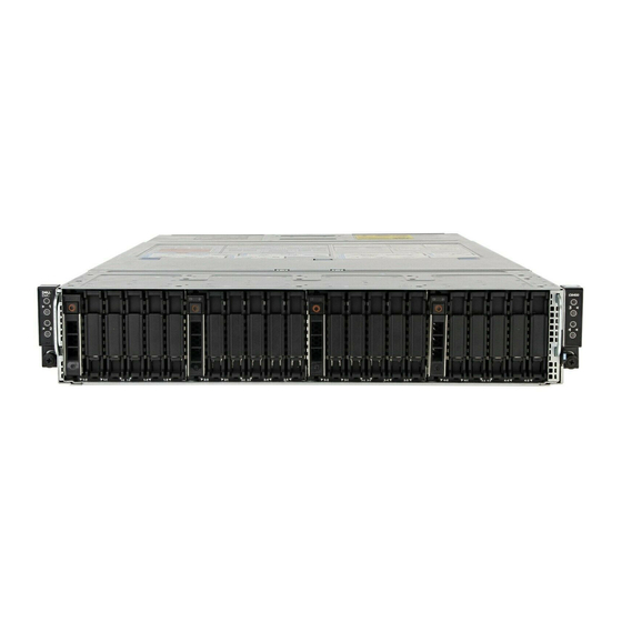
Front view of the Dell EMC PowerEdge C6400 enclosure Figure 2. Front view of the enclosure with 24 x 2.5-inch drives 1. Left control panel 2. Drive bay 3. Right control panel 4. EST tag Figure 3. Front view of the enclosure with 12 x 3.5-inch drives 1. - Page 9 • To turn the system ID on or off. NOTE: If the sled stops responding during POST, press and hold the system ID button (for more than five seconds) to enter the BIOS progress mode. Dell EMC PowerEdge C6400 overview...
-
Page 10: Rear View Of The Enclosure With Sleds
2. Drives 3–5 mapped to sled 2 3. Drives 6–8 mapped to sled 3 4. Drives 9–11 mapped to sled 4 NOTE: The warranty of the drives are linked to the Service Tag of the corresponding sled. Dell EMC PowerEdge C6400 overview... -
Page 11: Expander Zoning
A SAS expander board allows higher, single-volume hard drive configurations. An integrated expander device expands each sleds hard drive footprint. The Dell EMC PowerEdge C6400 enclosure allows four sleds to access a single expander controller at the same time. there are two zoning options available, they are: •... -
Page 12: Diagnostic Indicators
Flashes amber four times per second Drive failed. Flashes green slowly Drive rebuilding. Solid green Drive online. Flashes green for three seconds, amber for three seconds, Rebuild stopped. and then turns off after six seconds Dell EMC PowerEdge C6400 overview... -
Page 13: Power Supply Unit Indicator Codes
Your system is identified by a unique Express Service Code and Service Tag number. The Express Service Code and Service Tag are found on the front of the enclosure by pulling out the EST tag. This information is used by Dell to route support calls to the appropriate personnel. -
Page 14: System Information Label
Figure 10. Locating the Service Tag of your system 1. Information tag (top view) 2. QR code label 3. Express Service Tag label System information label Sled service information Figure 11. Sled service information Dell EMC PowerEdge C6400 overview... - Page 15 Cable routing Figure 12. Cable routing Dell EMC PowerEdge C6400 overview...
- Page 16 Mechanical overview Figure 13. Mechanical overview Link board and Drive cage Figure 14. Link board and Drive cage Dell EMC PowerEdge C6400 overview...
- Page 17 Jumper settings Figure 15. Jumper settings System tasks Figure 16. System tasks Dell EMC PowerEdge C6400 overview...
-
Page 18: Documentation Resources
Configuring your system For information about the iDRAC features, www.dell.com/poweredgemanuals configuring and logging in to iDRAC, and managing your system remotely, see the Integrated Dell Remote Access Controller User's Guide. For information about understanding Remote Access Controller Admin (RACADM) subcommands and supported RACADM interfaces, see the RACADM CLI Guide for iDRAC. - Page 19 For information about installing, using, and www.dell.com/openmanagemanuals > troubleshooting Dell OpenManage Essentials, see OpenManage Essentials the Dell OpenManage Essentials User’s Guide. For information about installing and using Dell www.dell.com/serviceabilitytools SupportAssist, see the Dell EMC SupportAssist Enterprise User’s Guide. For information about partner programs enterprise www.dell.com/openmanagemanuals...
-
Page 20: Technical Specifications
Technical specifications The technical and environmental specifications of your system are outlined in this section. Topics: • Dimensions of the Dell EMC PowerEdge C6400 enclosure • Chassis weight • Supported operating systems • PSU specifications • Chassis management board specifications •... -
Page 21: Chassis Weight
Chassis weight Table 6. Chassis weight of the Dell EMC PowerEdge C6400 enclosure with PowerEdge C6420 sleds System Maximum weight (with all sleds and drives) 12 x 3.5-inch hard drive systems 43.62 Kg (96.16 lb) 24 x 2.5-inch hard drive systems 41.46 Kg (91.40 lb) -
Page 22: Chassis Management Board Specifications
11. Fan cage 2 connector for fans 3 and 4 Drives and storage specifications The Dell EMC PowerEdge C6400 enclosure supports SAS and SATA hard drives and Solid State Drives (SSDs). Table 8. Supported drive options for the Dell EMC PowerEdge C6400 enclosure... -
Page 23: Midplane Specifications
Standard operating temperature specifications NOTE: 1. Not available: Indicates that the configuration is not offered by Dell EMC. 2. Not supported: Indicates that the configuration is not thermally supported. NOTE: All components including the DIMMs, communication cards, M.2 SATA, and PERC cards can be supported with sufficient thermal margin if the ambient temperature is equal to or below to the maximum continuous operating temperature listed in these tables except for the Mellanox DP LP card and Intel Rush Creek card. - Page 24 Table 10. Standard operating temperature specifications Standard operating temperature Specifications Temperature ranges (for altitude less than 950 m or 3117 ft) 10°C–35°C (50°F–95°F) with no direct sunlight on the equipment. NOTE: Some configurations require a lower ambient temperature. For more information, see the following tables. Table 11.
- Page 25 No-BP 3.5-inch chassis 2.5-inch chassis Chassis memor Process Heat sink Watts or model model proces Drive Drive Drive Driv Drive Driv Drive Drives Drives CPU1: CPU1: JYKMM | 8260L CPU2: CPU2: V2DRD CPU1: CPU1: JYKMM | 8260M CPU2: CPU2: V2DRD CPU1: CPU1: JYKMM |...
- Page 26 No-BP 3.5-inch chassis 2.5-inch chassis Chassis memor Process Heat sink Watts or model model proces Drive Drive Drive Driv Drive Driv Drive Drives Drives CPU2: CPU2: V2DRD CPU1: CPU1: JYKMM | 8253 CPU2: CPU2: V2DRD CPU1: CPU1: JYKMM | 6238T CPU2: CPU2: V2DRD...
- Page 27 No-BP 3.5-inch chassis 2.5-inch chassis Chassis memor Process Heat sink Watts or model model proces Drive Drive Drive Driv Drive Driv Drive Drives Drives CPU1: CPU1: JYKMM | 4215 CPU2: CPU2: V2DRD CPU1: CPU1: JYKMM | 4214 CPU2: CPU2: V2DRD CPU1: CPU1: JYKMM |...
- Page 28 No-BP 3.5-inch chassis 2.5-inch chassis Chassis Heat memor Processor TDP Watts sink model model proces Drive Driv Driv Driv Drive Driv Drive Drives Drives CPU1: 8276 CPU1: 8 JYKMM CPU1: 8276L CPU1: 8 JYKMM CPU1: 8276M CPU1: 8 JYKMM CPU1: 8260 CPU1: 8 JYKMM...
- Page 29 No-BP 3.5-inch chassis 2.5-inch chassis Chassis Heat memor TDP Watts Processor sink model model proces Drive Driv Driv Driv Drive Driv Drive Drives Drives CPU1: 5218T CPU1: 6 FMM2M CPU1: 5218N CPU1: 6 FMM2M 105 W CPU1: 5222 CPU1: 6 FMM2M CPU1: 8256...
- Page 30 No-BP 3.5-inch chassis 2.5-inch chassis Chassis TDP Watts 12x HDDs 8x HDDs 4x HDDs 24x HDDs 16x HDDs 8x HDDs 4x HDDs 150 W supported supported supported 140 W supported 135 W supported 130 W supported 125 W 115 W >35 113 W >35...
-
Page 31: Expanded Operating Temperature Specifications
Table 15. Configuration Restrictions with Intel NVMe SSD AIC P4800X No-BP 3.5-inch chassis 2.5-inch chassis Chassis TDP Watts 12x HDDs 8x HDDs 4x HDDs 24x HDDs 16x HDDs 8x HDDs 4x HDDs 205 W supported supported supported supported supported supported supported supported 200 W... -
Page 32: Particulate And Gaseous Contamination Specifications
NOTE: When operating in the expanded temperature range, system performance may be impacted. NOTE: When operating in the expanded temperature range, ambient temperature warnings may be reported in the System Event Log. Operating temperature derating specifications Table 17. Operating temperature Operating temperature derating Specifications <... -
Page 33: Maximum Vibration Specifications
Particulate contamination Specifications NOTE: This condition applies only to data center environments. Air filtration requirements do not apply to IT equipment designed to be used outside a data center, in environments such as an office or factory floor. NOTE: Air entering the data center must have MERV11 or MERV13 filtration. Conductive dust Air must be free of conductive dust, zinc whiskers, or other conductive particles. -
Page 34: Fresh Air Operation
Maximum altitude Specifications Storage 12,000 m (39,370 ft) Fresh Air Operation Fresh Air operation restrictions • Processors with a TDP greater than 105 W are not supported • Support for processors of 85 W and below without PERC restrictions • 3.5-inch drive configuration is not supported •... -
Page 35: Installing And Removing Enclosure Components
Damage due to servicing that is not authorized by Dell is not covered by your warranty. Read and follow the safety instructions that are shipped with your product. -
Page 36: After Working Inside Your System
2. Disconnect the system from the electrical outlet and disconnect the peripherals. 3. If applicable, remove the system from the rack. For more information, see the Rack Installation Guide at www.dell.com/poweredgemanuals. 4. Remove the system cover. After working inside your system... -
Page 37: Removing A Sled
Figure 20. Sled Installation Guidelines Removing a sled Prerequisites 1. Follow the safety guidelines listed in Safety instructions. 2. Follow the procedure listed in Before working inside your enclosure. NOTE: The process of removing a sled blank is similar to removing a sled. Steps Press the retaining latch and using the sled pull handle, slide the sled out of the enclosure horizontally, ensuring that the sled is supported from beneath. - Page 38 Figure 21. Removing a sled Figure 22. Removing a sled blank Next steps Install the sled into the enclosure. Installing and removing enclosure components...
-
Page 39: Installing A Sled
NOTE: If the sled is not being replaced immediately, a sled blank must be installed to ensure proper cooling of the system. Installing a sled Prerequisites 1. Follow the safety guidelines listed in Safety instructions. 2. If installed, remove the sled blank. -
Page 40: Drives
1. Follow the procedure listed in After working inside your enclosure. NOTE: To add the Service Tag of the system board to match the Service Tag of the physical node, contact Dell Technical Support. Drives CAUTION: Before attempting to remove or install a drive while the system is running, see the documentation for the storage controller card to ensure that the host adapter is configured correctly. -
Page 41: Installing A Drive Blank
Steps Press the release button, and slide the drive blank out of the drive slot. Figure 25. Removing a drive blank Next steps Install a drive or a drive blank. Installing a drive blank The procedure for installing 2.5-inch and 3.5-inch drive blanks is identical. Prerequisites 1. -
Page 42: Installing A Drive Carrier
CAUTION: Mixing drives from previous generations of PowerEdge servers is not supported. CAUTION: To prevent data loss, ensure that your operating system supports drive installation. See the documentation supplied with your operating system. Steps 1. Press the release button to open the drive carrier release handle. 2. -
Page 43: Removing The Drive From The Drive Carrier
2. If applicable, remove the drive blank. Steps 1. Press the release button on the front of the drive carrier to open the release handle. 2. Insert and slide the drive carrier into the drive slot. 3. Close the drive carrier release handle until it clicks in place. Figure 28. -
Page 44: Installing A Drive Into The Drive Carrier
Figure 29. Removing the drive from the drive carrier Next steps 1. If applicable, install the drive into the drive carrier. Installing a drive into the drive carrier Prerequisites CAUTION: Mixing drive carriers from other generations of PowerEdge servers is not supported. NOTE: When installing a drive into the drive carrier, ensure that the screws are torqued to 4 in-lbs. -
Page 45: Power Supply Units
Figure 30. Installing a drive into the drive carrier Next steps Install the drive carrier. Power supply units CAUTION: The PSUs must have the Extended Power Performance (EPP) label. Mixing PSUs (even the PSUs that have the same power rating) from previous generations of PowerEdge servers is not supported. Mixing PSUs results in a PSU mismatch condition or failure to turn the system on. -
Page 46: Removing A Power Supply Unit
Policy control As with all Redundancy Policies, while the two Power Supplies remain healthy, load is shared evenly between them and the capacity of both Power Supplies is made available for use. In the event of an AC Grid or Power Supply failure, Power Controls will rapidly engage to restrict the power consumption of the chassis and ensure that consumption is restricted to what a single Power Supply can support. -
Page 47: Installing A Power Supply Unit
Next steps Install the PSU install the PSU blank Installing a power supply unit Prerequisites 1. Follow the safety guidelines listed in Safety instructions. 2. For systems that support redundant PSU, ensure that both the PSUs are of the same type and have the same maximum output power. -
Page 48: Installing The System Cover
Damage due to servicing that is not authorized by Dell is not covered by your warranty. Read and follow the safety instructions that are shipped with your product. -
Page 49: Backplane Cover
Figure 34. Installing the system cover Next steps 1. Reconnect the peripherals, and connect the system to the electrical outlet. 2. Power on the system, and all attached peripherals. Backplane cover Removing the backplane cover Prerequisites NOTE: This procedure is not applicable for enclosures with the 3.5-inch hard drive configuration. 1. -
Page 50: Installing The Backplane Cover
Figure 35. Removing the backplane cover Next steps Install the backplane cover. Installing the backplane cover Prerequisites 1. Follow the safety guidelines listed in Safety instructions. Steps 1. Align the screw holes on the backplane cover with the screw holes on the chassis by sliding the cover toward the front of the enclosure. -
Page 51: Cooling Fans
Next steps 1. Follow the procedure listed in After working inside your enclosure. Cooling fans Removing a cooling fan Prerequisites WARNING: Do not attempt to operate the system without the cooling fans. WARNING: The cooling fan spins for some time after the system is powered off. Allow the fan to stop spinning before removing it from the system. -
Page 52: Removing The Cooling Fan Cage
Figure 38. Installing a cooling fan Next steps 1. Follow the procedure listed in After working inside your enclosure. 2. Check the management software to see if the fan is rotating at the optimal speed. Removing the cooling fan cage Prerequisites WARNING: Do not attempt to operate the system without the cooling fans. -
Page 53: Installing The Cooling Fan Cage
Figure 39. Removing the cooling fan cage Next steps Install the cooling fan cage. Installing the cooling fan cage Prerequisites WARNING: Do not attempt to operate the system without the cooling fans. NOTE: Observe the routing of the cables when removing them from the system. Route these cables properly when you replace them to prevent the cables from being pinched or crimped. -
Page 54: Power Interposer Board
Figure 40. Installing the cooling fan cage Next steps Install the cooling fans. 2. Follow the procedure listed in After working inside your enclosure. 3. Check the management software to see if all the fans are rotating at the optimal speed. Power interposer board Removing the power interposer board Prerequisites... - Page 55 Figure 41. Removing the PIB Figure 42. Removing the midplane power cables from the PIB Next steps Install the PIB. Installing and removing enclosure components...
-
Page 56: Installing The Power Interposer Board
Installing the power interposer board Prerequisites WARNING: Allow the power interposer board (PIB) to discharge after you power off the system. Handle the PIB by the edges and avoid touching the contact surfaces of the connectors. 1. Follow the safety guidelines listed in Safety instructions. -
Page 57: Chassis Management Board
Figure 44. Installing the PIB Next steps 1. Reconnect all the disconnected cables. Install the power supply units. 3. Follow the procedure listed in After working inside your enclosure. Chassis management board Removing the chassis management board Prerequisites 1. Follow the safety guidelines listed in Safety instructions. -
Page 58: Installing The Chassis Management Board
Figure 45. Removing the chassis management board Next steps Install the chassis management board. Installing the chassis management board Prerequisites 1. Follow the safety guidelines listed in Safety instructions.. Steps 1. Insert the chassis management board into the enclosure, aligning the guide slots with the standoffs on the chassis. 2. -
Page 59: Linking Board
Next steps 1. Reconnect all the disconnected cables. Install the power interposer board. Install the power supply units. 4. Follow the procedure listed in After working inside your enclosure. Linking board Removing the linking board Prerequisites 1. Follow the safety guidelines listed in Safety instructions. -
Page 60: Installing The Linking Board
Figure 48. Removing the left linking board Next steps Install the linking board. Installing the linking board Prerequisites 1. Follow the safety guidelines listed in Safety instructions. Steps 1. Reconnect all the disconnected cables to the linking board. 2. Align the board with the standoff on the chassis and slide the board into place. NOTE: Ensure that the linking board cable connector is not folded or twisted while installing the sled, to avoid damaging the linking board cable connector. - Page 61 Figure 49. Installing the right linking board Figure 50. Installing the left linking board Next steps Install the fan cage. Install the sleds into the enclosure. 3. Follow the procedure listed in After working inside your enclosure. Installing and removing enclosure components...
-
Page 62: Midplane
Midplane Removing the right midplane Prerequisites NOTE: Observe the routing of the cables on the chassis as you remove them from the system. Route these cables properly when you replace them to prevent the cables from being pinched or crimped. 1. -
Page 63: Removing The Left Midplane
Steps 1. Using the Phillips #1 screwdriver, connect and secure the power cables to the midplane. 2. Place the midplane into the chassis. 3. Using the Phillips #1 screwdriver, tighten the screws that secure the midplane to the chassis. Figure 52. Installing the right midplane Next steps 1. -
Page 64: Installing The Left Midplane
Figure 53. Removing the left midplane Next steps Install the midplanes. Installing the left midplane Prerequisites NOTE: You must route the cables properly on the chassis to prevent them from being pinched or crimped. 1. Follow the safety guidelines listed in Safety instructions. -
Page 65: Midplane Power Cable Routing
Figure 54. Installing the left midplane Next steps 1. Connect all the disconnected cables. Install the cooling fan cage. 3. Follow the procedure listed in After working inside your enclosure.. Midplane power cable routing Figure 55. Midplane power cable routing from power interposer board 1. -
Page 66: Drive Cage
5. +12 V power cable for right midplane 6. GND cable for right midplane 7. right midplane Drive cage Removing the 2.5 inch drive cage Prerequisites CAUTION: To prevent damage to the drives and backplane, you must remove the drives from the system before removing the backplane. -
Page 67: Installing The 2.5 Inch Drive Cage
Installing the 2.5 inch drive cage Prerequisites CAUTION: To prevent damage to the drives and backplane, you must remove the drives from the system before removing the backplane. CAUTION: You must note the number of each drive and temporarily label them before removal so that you can replace them in the same locations. -
Page 68: Installing The 3.5 Inch Drive Cage
1. Follow the safety guidelines listed in Safety instructions. 2. Follow the procedure listed in Before working inside your enclosure. Remove the fan cages. 4. Disconnect the backplane cables from the linking board and chassis management board. Remove all the drives. -
Page 69: Backplanes And Expander Board
Figure 59. Installing the 3.5-inch drive cage Next steps 1. Reconnect all the backplane cables that were disconnected from the linking board and chassis management board. Install all the drives. Install the fan cages. 4. Follow the procedure listed in After working inside your enclosure. - Page 70 Figure 61. 24 x 2.5-in hard drive backplane 1. SATA connector (24) 2. Expander power connector 3. Backplane power connector 4. Backplane signal connector The image below shows the 24 x 2.5-in hard drive backplane with NVMe: Figure 62. 24 x 2.5-in hard drive backplane with NVMe 1.
- Page 71 Figure 63. SAS Expander board 1. Expander signal cable connector 2 2. Power connector 3. SAS expander F connector 4. SAS expander E connector 5. SAS expander D connector 6. PERC 3 expander and PERC 4 expander connector 7. PERC 1 expander and PERC 2 expander connector 8.
- Page 72 7. NVMe connector for sled 2 8. NVMe connector for sled 1 9. Left linking board 10. Linking board connector for sled 1 11. Linking board connector for sled 2 12. SATA cable for sled 2(BP: sled 2 to MB: left linking board) 13.
- Page 73 Figure 66. Cabling the 12 x 3.5-inch backplane 1. Backplane 2. SATA cable for sled 1(BP: SATA cable sled 1 to left linking board) 3. Signal cable sled 1(BP: BP_SIG1 to left linking board) 4. Linking board connector for sled 1 5.
- Page 74 Figure 68. Sled to drive mapping for the enclosure with 12 x 3.5-inch drives 1. Drives 0–2 mapped to sled 1 2. Drives 3–5 mapped to sled 2 3. Drives 6–8 mapped to sled 3 4. Drives 9–11 mapped to sled 4 NOTE: The warranty of the drives are linked to the Service Tag of the corresponding sled.
-
Page 75: Removing The Backplane
NOTE: • Install expander firmware 2.07 (X25-00) or later to support these configurations • The expander mode works only with a PERC card, and is not supported by the onboard SATA controller. Removing the backplane Prerequisites CAUTION: To prevent damage to the drives and backplane, you must remove the drives from the system before removing the backplane. -
Page 76: Installing The Backplane
Figure 69. Removing the backplane Next steps Install the backplane. Installing the backplane Prerequisites CAUTION: You must note the slot number of each drive and temporarily label them before removal so that you can replace them in the same slots. NOTE: Observe the routing of the cables on the chassis as you remove them from the system. -
Page 77: Removing The Backplane Expander Board
Figure 70. Installing the backplane Next steps 1. Reconnect all the disconnected cables. Install the drive cage into the enclosure. 3. Follow the procedure listed in After working inside your enclosure. Removing the backplane expander board Prerequisites NOTE: To prevent damage to the drives and backplane, you must remove the drives from the system before removing the backplane. -
Page 78: Installing The Backplane Expander Board
Steps 1. Using the Phillips #2 screwdriver, remove the screws that secure the backplane expander board to the drive cage. 2. Lift the backplane expander board out of the enclosure. Figure 71. Removing the backplane expander board Next steps Install the backplane expander board. -
Page 79: Control Panel
Figure 72. Installing the backplane expander board Next steps 1. Reconnect all the disconnected cables. Install the drive cage. 3. Follow the procedure listed in After working inside your enclosure. Control panel Removing the control panel Prerequisites NOTE: Observe the routing of the cables on the enclosure as you remove them. You must route these cables properly when you replace them to prevent the cables from being pinched or crimped. -
Page 80: Installing The Control Panel
Figure 73. Removing the left control panel assembly Figure 74. Removing the right control panel assembly Next steps Install the control panel assembly. Installing the control panel Prerequisites NOTE: Observe the routing of the cables on the chassis as you remove them from the system. You must route these cables properly when you replace them to prevent the cables from being pinched or crimped. - Page 81 1. Follow the safety guidelines listed in Safety instructions. Steps 1. Route the control panel cable through the cable retention clips. 2. Install the control panel assembly and secure it in place with screws. Figure 75. Installing the left control panel Figure 76.
-
Page 82: Thermal Sensor Board
Thermal sensor board Removing the thermal sensor board Prerequisites CAUTION: To prevent damage to the drives and backplane, you must remove the drives from the system before removing the backplane. CAUTION: You must note the number of each drive and temporarily label them before removal so that you can replace them in the same locations. - Page 83 1. Follow the safety guidelines listed in Safety instructions. Steps 1. Install the thermal sensor board into the sensor board holder, and using the Phillips #1 screwdriver, secure it to the holder. 2. Connect the cable to the sensor board assembly. 3.
-
Page 84: Getting Help
The Contact Technical Support page is displayed with details to call, chat, or e-mail the Dell EMC Global Technical Support team. Documentation feedback You can rate the documentation or write your feedback on any of our Dell EMC documentation pages and click Send Feedback to send your feedback. -
Page 85: Quick Resource Locator For C6400 And C6420 Systems
Receiving automated support with SupportAssist Dell EMC SupportAssist is an optional Dell EMC Services offering that automates technical support for your Dell EMC server, storage, and networking devices. By installing and setting up a SupportAssist application in your IT environment, you can receive the following benefits: •...