Table of Contents
Advertisement
Quick Links
Advertisement
Table of Contents

Related Manuals for ABB RSYC-01


Summary of Contents for ABB RSYC-01
- Page 1 ACS800 User’s Manual RSYC-01 Synchronizing Unit...
- Page 3 RSYC-01 Synchronizing Unit User’s Manual Code: 3AFE68827370 REV A EFFECTIVE: 29.06.2007 FIDRI\EIF200 © 2007 ABB Oy. All Rights Reserved.
-
Page 5: Table Of Contents
Operation ............................9 Overall view of the unit ........................10 RSYC-01 unit with cover......................10 RSYC-01 unit without cover ....................... 10 Connection diagram ........................11 Terminals/connections of the RSYC unit ..................12 Connections of RSYC unit to the drive ................... 12 Mechanical installation ........................ - Page 6 Resetting the system........................20 Fault tracing...........................21 What this chapter contains ......................21 Troubleshooting hints ........................21 Measuring with an oscilloscope .......................22 Miscellaneous measurement graphs ....................24 Technical data ..........................25 Dimension drawing ........................27 Cover of the RSYC enclosure ......................27 RSYC enclosure body ........................28 Table of contents...
-
Page 7: Introduction To The Manual
This chapter includes a description of the contents of the manual. In addition it contains information about the compatibility, safety and intended audience. Compatibility The manual is compatible with RSYC-01 Synchronizing Unit. The drive parameter data refers to ACS800 Standard Control Program. Safety instructions Follow all safety instructions delivered with the drive. - Page 8 Introduction to the manual...
-
Page 9: Description Of Operation And Hardware
Description of operation and hardware What this chapter contains This chapter describes the operation of a synchronization application, shows a connection diagram and presents the RSYC unit. Intended use of the RSYC unit A drive equipped with the RSYC unit is designed for applications in which a large fixed-speed motor must be started to a weak supply line. -
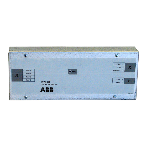
Page 10: Overall View Of The Unit
Overall view of the unit RSYC-01 unit with cover RSYC-01 unit without cover 1) +24 V DC supply for the RSYC-01 unit 2) SYNC signal (K4) and BUF OUT signal 3) Inverter output (T2) and network supply (T1) measurement transformer signals 4) Cable screen clamps. -
Page 11: Connection Diagram
Connection diagram Description of operation and hardware... -
Page 12: Terminals/Connections Of The Rsyc Unit
T1 – Supply line voltage measurement as 10 … 120 V AC signal (3-phase potential measuring transformer with static shield) T2 – Motor voltage measurement as 10 … 120 V AC signal (3-phase potential measuring transformer with static shield) Terminals/connections of the RSYC unit Terminal Name Description... -
Page 13: Mechanical Installation
Mechanical installation What this chapter contains This chapter contains mounting rail instructions and contents of the RSYC kit. Delivery check / contents of the RSYC kit RSYC kit contains: RSYC unit • two synchronizing transformers • 8 meters of cable for RSYC connections •... -
Page 14: Mechanical Installation
Mechanical installation Mounting the RSYC unit Mount the unit by snapping the feet onto a 7.5 × 35 mm mounting rail (1) (2). Mounting Mechanical instalation... -
Page 15: Electrical Installation
Electrical installation What this chapter contains This chapter contains a reference to the connection diagram and a list of items to consider in the electrical installation. Connection diagram Connection diagram on page Considerations Follow the cabling recommendations of the drive Hardware Manual. Leave at least 0.5 m space between the unit and the power cables and drive module. -
Page 16: Cable Clamping And Grounding Example
Cable clamping and grounding example To network supply To inverter output measurement supply measurement transformer transformer SYNC +24 V DC BUF OUT signal supply signal Electrical installation... -
Page 17: Start-Up
Start-up What this chapter contains This chapter instructs in setting the drive parameters and in checking the system. Parameter settings The table below instructs in parameter settings for a drive with ACS800 Standard Control Program starting a four-pole motor (50 Hz). With these settings, the trim control can affect ±20 rpm to final speed reference (1% of the defined maximum speed limit). -
Page 18: Checking The Operation Of The Rsyc Unit
Setting Parameter value Additional information Select analogue input AI1 for actual 40.07 = AI1 BUF OUT signal from RSYC unit, 0 … 10 V. signal for PID controller. Below 5 V = supply line frequency exceeds drive output frequency. 5 V = Supply line frequency and drive output frequency are equal and phases match. -
Page 19: Checking Of The Trim Function And Synchronization
Action Additional information Check unit visually. Parameter settings on page 17. Set drive parameters according to instructions. However, switch Trim function off (parameter 40.14 = OFF) for the time being. Shift control panel to local control mode. Use LOC/REM key. Letter L on first row of display indicates local control. -
Page 20: Final Check
Actions Information Start drive and monitor panel and RSYC status LED. The following indicates successful Trim control loop: - Drive accelerates to speed reference which was defined above. - Output frequency starts oscillating around 50 Hz. - AI1 is 2.5 V … 7 V. - RSYC LED blinks the first time after 5 …... -
Page 21: Fault Tracing
Fault tracing What this chapter contains This chapter gives the troubleshooting information. Troubleshooting hints Trouble Cause Remedy Unit operates illogically The board is affected by radiated Ensure all cables that connect to the RSYC unit despite all connections and interference. BUF OUT signal is not are shielded and shields are properly grounded. -
Page 22: Measuring With An Oscilloscope
Measuring with an oscilloscope Checking the supply line (MAINS) and inverter output (INVRTR) signals from the board may be the only way to see what is actually happening if there is no SYNC signal. There is a potential interference risk as it is possible that the probes pick-up the interference and conduct it to the board circuits. - Page 23 When the signals are in synchronization, the oscilloscope shows the following waveforms. When there is a phase difference, the waveforms are as shown in the graphic below. When the frequencies are different, the signals move respective to each other. If the “speed”...
-
Page 24: Miscellaneous Measurement Graphs
Miscellaneous measurement graphs The graph below shows the measurements of the voltages (U and U ) and phase currents (I and I ) when synchronizing to the network. 1200 1000 Uu-v Uv-w 96 191 286 381 476 571 666 761 856 951 1046 1141 1236 1331 1426 -200 -400 -600... -
Page 25: Technical Data
Technical data RSYC power supply voltage 24 V DC (-5 … +5%) RSYC power consumption 25 … 35 mA Signal cable type JAMAK by NK Cables Signal cable size 2 × (2+1) × 0.5 mm Signal cable use Connection of the RSYC unit to the drive, transformers and control relays Synchronization accuracy -21 …... - Page 26 Technical data...
-
Page 27: Dimension Drawing
Dimension drawing Cover of the RSYC enclosure The dimensions are given in millimetres. Dimension in mm. 1 mm = 0.039” 1” = 25.4 mm Dimension drawing... -
Page 28: Rsyc Enclosure Body
RSYC enclosure body Dimension drawing... - Page 30 ABB Oy ABB Inc. ABB Beijing Drive Systems Co. Ltd. AC Drives Automation Technologies No. 1, Block D, A-10 Jiuxianqiao Beilu P.O. Box 184 Drives & Motors Chaoyang District FI-00381 HELSINKI 16250 West Glendale Drive Beijing, P.R. China, 100015 FINLAND...