Bosch B9512G Installation Manual
Hide thumbs
Also See for B9512G:
- Program entry manual (284 pages) ,
- Owner's manual (228 pages) ,
- Installation and system reference manual (186 pages)
Table of Contents
Advertisement
Advertisement
Table of Contents

Related Manuals for Bosch B9512G


Summary of Contents for Bosch B9512G
- Page 1 Control panels B9512G/B8512G (B9512G‑E/B8512G‑E) UL Installation manual...
-
Page 3: About Documentation
These indicate a hazardous situation which, if not avoided, could result in death or serious injury. Copyright This document is the intellectual property of Bosch Security Systems, Inc. and is protected by copyright. All rights reserved. Trademarks All hardware and software product names used in this document are likely to be registered trademarks and must be treated accordingly. - Page 4 | Introduction Control panels Control Panels (B9512G/B8512G/B6512/B5512/B4512/B3512) ULC Installation Manual *Shipped with the control panel. Located on the documentation CD shipped with the control panel. Keypad documents Basic Keypad (B915) Installation Guide* Two-line Alphanumeric Keypad (B920) Installation Guide* Fire Keypads (B925F/B926F) Installation Guide*...
- Page 5 Located on the documentation CD shipped with the module. Bosch Security Systems, Inc. product manufacturing dates Use the serial number located on the product label and refer to the Bosch Security Systems, Inc. website at http://www.boschsecurity.com/datecodes/. Bosch Security Systems B.V.
-
Page 6: System Overview
Control panels ship assembled from the factory with the following parts: Literature – Control Panels (B9512G/B8512G) UL Installation Manual – Control Panels (B9512G/B8512G/B5512/B4512/B3512) Operation Manual – Control Panels (B9512G/B8512G) SIA Quick Reference Guide – Control Panels (B9512G/B8512G) Documentation CD – Product Label in French – 7000/9000 Series Point Chart Label HW pack –... - Page 7 8 doors using the optional D9210C Access Control Interface Module. The control panel supports up to 16 of the keypads as SDI keypads. Bosch IP cameras use is supplementary in UL Listed systems. Bosch Security Systems B.V.
-
Page 8: Control Panel Installation
Align the Holes to attach the mounting skirt to hooks with the hooks. Slide the control panel down so that it hangs on the hooks. Secure the mounting skirt screw. 2019-12 | 06 | F.01U.304.001 UL Installation manual Bosch Security Systems B.V. -
Page 9: Earth Ground
Set your digital voltmeter (DVM) to measure VDC. Connect the red DVM lead to control panel Terminal 10, and the black DVM lead to Terminal 9. Compare this voltage to the following table. Bosch Security Systems B.V. UL Installation manual 2019-12 | 06 | F.01U.304.001... -
Page 10: Control Panel To Module Wiring Overview
If SDIx is configured for SDI2, use either SDI2 bus. Using terminal wiring in parallel Notice! Wire size For terminal wiring, use 18 AWG to 22 AWG (1.0 mm to 0.6 mm) wire. 2019-12 | 06 | F.01U.304.001 UL Installation manual Bosch Security Systems B.V. - Page 11 PWR+/R COM/B COM/B ZONEX ZONEX TAMPER TAMPER RESET RESET ZONEX TMPR Using interconnect wiring Notice! More information For more information on interconnect wiring, refer to SDI2 interconnect wiring. Bosch Security Systems B.V. UL Installation manual 2019-12 | 06 | F.01U.304.001...
- Page 12 SDI2 devices daisy chained with interconnect wiring MOD-2 MODULE RELEASE MOD-1 PWR+/R PWR+/R olice olice ting ting COM/B COM/B PWR+/R PWR+/R COM/B COM/B ZONEX ZONEX TAMPER TAMPER RESET RESET ZONEX TMPR 2019-12 | 06 | F.01U.304.001 UL Installation manual Bosch Security Systems B.V.
-
Page 13: Power Supply
Maintain a 0.250 in (6.4 mm) space between the battery terminals, battery wiring, and all other wiring. Battery wiring cannot share the same conduit, conduit fittings, or conduit knockouts with other wiring. Bosch Security Systems B.V. UL Installation manual 2019-12 | 06 | F.01U.304.001... - Page 14 Allow the control panel to charge the battery while you complete the installation. 4.1.2 BATTERY STATUS LED The control panel includes one BATTERY STATUS LED with 4 LED patterns to indicate the battery status. 2019-12 | 06 | F.01U.304.001 UL Installation manual Bosch Security Systems B.V.
-
Page 15: Battery Maintenance
Low System Battery Restore report in the Conettix Modem4 format or a Control Panel Battery Restored to Normal (302) report in the Conettix ANSI-SIA Contact ID format. Bosch Security Systems B.V. UL Installation manual 2019-12 | 06 | F.01U.304.001... -
Page 16: Battery Charging Circuit Float Charge
The power supply draws approximately 15 mA (+/- 1 mA) from the control panel. For detailed instructions, refer to the corresponding document listed in Related documentation, page 3. 2019-12 | 06 | F.01U.304.001 UL Installation manual Bosch Security Systems B.V. -
Page 17: Sdi2 Address Settings
16 AWG (1.5 mm) wire when making the connection Use a grounding rod or a cold water pipe. Run wire as close as possible to grounding device. Bosch Security Systems B.V. UL Installation manual 2019-12 | 06 | F.01U.304.001... -
Page 18: Powered Device And Battery Wiring
When you wire the output of a B520 to a SDI2 module, the B520 provides power to the module while passing through data between the control panel and the module. 2019-12 | 06 | F.01U.304.001 UL Installation manual Bosch Security Systems B.V. - Page 19 You must wire BATT 1. You must wire BATT 2 if you configure the B520 for two batteries. When you use BATT 2, both batteries must have the same rating. Maximum standby power cannot exceed 36 Ah. Callout ᅳ Description Bosch Security Systems B.V. UL Installation manual 2019-12 | 06 | F.01U.304.001...
- Page 20 1 ᅳ B520 Auxiliary Power Supply Module 2 ᅳ Battery 2 (BATT 2) - (12 V nominal lead acid) 3 ᅳ Battery 1 (BATT 1) - (12 V nominal lead acid) 2019-12 | 06 | F.01U.304.001 UL Installation manual Bosch Security Systems B.V.
-
Page 21: Total Available Power
SDIx Power+ / R Powers serial device interface (SDI) keypads, or use to power serial device interface 2 (SDI2) devices, such as keypads and expansion modules. Bosch Security Systems B.V. UL Installation manual 2019-12 | 06 | F.01U.304.001... -
Page 22: Continuous Power Outputs
Nominal power output. Use the power at Terminals 6 and 7 to power bells, siren drivers, piezoelectric sounders, electronic horns, or other devices. Programming determines the format of the output and the conditions that activate it. 2019-12 | 06 | F.01U.304.001 UL Installation manual Bosch Security Systems B.V. -
Page 23: Usb Power
The USB POWER STATUS LED lights when power to the USB is turned on. You can disable USB at any time. Use the Installer menu or press the control panel RESET button 3 times. Bosch Security Systems B.V. UL Installation manual 2019-12 | 06 | F.01U.304.001... -
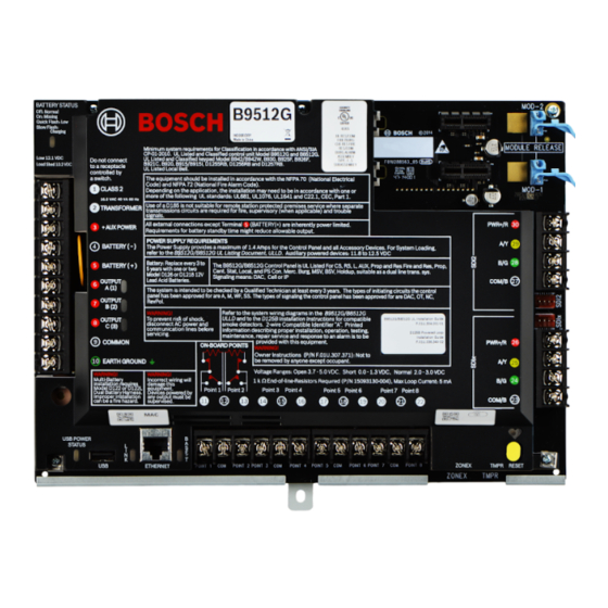
Page 24: Control Panel Board Overview
B9512G/B8512G UL Listing Document, ULLD. Auxiliary powered devices: 11.8 to 12.5 VDC Battery: Replace every 3 to The B9512G/B8512G Control Panel is UL Listed For CS, RS, L, AUX, Prop and Res Fire and Res, Prop, BATTERY ( + ) 5 years with one or two Cent. -
Page 25: System Wiring Diagrams
All terminals except Outputs A (1), B (2), and C (3) (Terminals 6, 7, and 8) are supervised. For proper supervision, do not loop wire under terminals. Break the wire run to provide supervision of connections. Bosch Security Systems B.V. UL Installation manual 2019-12 | 06 | F.01U.304.001... -
Page 26: Power Supply Side Wiring
12 ᅳ Listed audible signaling devices rated at 12.0 VDC nominal (do not use vibrating type horns) 6 ᅳ B520 Auxiliary Power Supply Module 13 ᅳ To earth ground 7 ᅳ To powered devices 2019-12 | 06 | F.01U.304.001 UL Installation manual Bosch Security Systems B.V. -
Page 27: Input Points Wiring With Or Without Eol Resistors
Input points wiring with or without EOL resistors Notice! EOL resistors For the dual EOL resistor circuit style order ICP-1K22AWG-10, package of 10 1.0 kΩ EOL resistors. Bosch Security Systems B.V. UL Installation manual 2019-12 | 06 | F.01U.304.001... -
Page 28: Sdi And Zonex Wiring
SDI and ZONEX wiring Notice! Install Fire and Intrusion devices only on separate circuits. Refer to the ICP-SDI-9114 Installation Instructions. All external connections except Terminal 5 (battery positive) are power limited. 2019-12 | 06 | F.01U.304.001 UL Installation manual Bosch Security Systems B.V. - Page 29 *The number of D8129 Octo-relay modules allowed for each ZONEX terminal on the B600 is limited by the number of D8128D OctoPOPITs connected to the same terminal. Refer to the D8128D Installation Guide or the D8129 Operation and Installation Guide for detailed instructions. Bosch Security Systems B.V. UL Installation manual 2019-12 | 06 | F.01U.304.001...
-
Page 30: Sdi2 Devices General System Wiring
SDI2 modules use the SDI2 bus to communicate with one another. You can wire modules via home run, daisy chain, or single level T-tap anywhere on the SDI2 bus. 2019-12 | 06 | F.01U.304.001 UL Installation manual Bosch Security Systems B.V. - Page 31 Refer to the SDI2 device or keypad documentation for the allowable maximum distance from the control panel. – Maximum overall cable lengths are listed in the following table: Bosch Security Systems B.V. UL Installation manual 2019-12 | 06 | F.01U.304.001...
-
Page 32: 2-Wire Smoke Wiring (D125B)
6 ᅳ Supervised smoke detector to B LOOP negative panel 2 ᅳ Supervised connection to Zone B power from an on- 7 ᅳ Supervised smoke detector to A LOOP negative board point of the control panel 2019-12 | 06 | F.01U.304.001 UL Installation manual Bosch Security Systems B.V. -
Page 33: Earth Ground Wiring
Measuring and comparing voltage for ground fault detection Set your digital voltmeter (DVM) to measure VDC. Connect the red DVM lead to control panel Terminal 10, and the black DVM lead to Terminal 9. Bosch Security Systems B.V. UL Installation manual 2019-12 | 06 | F.01U.304.001... - Page 34 11, 13, 14, 16, 17, 19, 20, 22 ~ 2.44 to 3.2 VDC ~ 10.9 to 11.2 VDC ~ 7.2 VDC ~ 5.8VDC ~ 7.35 VDC 1, 2 2019-12 | 06 | F.01U.304.001 UL Installation manual Bosch Security Systems B.V.
- Page 35 Alarm or Trouble silence. Press SILENCE and enter your passcode. Detector reset. Press RESET and enter your passcode (if required). You can also use [CMD][4][7], or the Menu to reset detectors. Bosch Security Systems B.V. UL Installation manual 2019-12 | 06 | F.01U.304.001...
- Page 36 Alarm or Trouble silence. Press SILENCE and enter your passcode. Detector reset. Press RESET and enter your passcode (if required). You can also use [CMD][4][7], or the Menu to reset detectors. 2019-12 | 06 | F.01U.304.001 UL Installation manual Bosch Security Systems B.V.
- Page 37 Detector reset. Press the COMMAND bar and select 4 + 7. Annunciating reset. Enter PIN (if required) and press ESC. This clears alarm or trouble memory from the keypad display, when all points are in a normal state. Bosch Security Systems B.V. UL Installation manual 2019-12 | 06 | F.01U.304.001...
- Page 38 Detector reset. Press the Detector Reset key to reset detection devices. Annunciating reset. Press the Annunciator Reset key to clear all alarm, trouble, and supervisory messages when all points are in a normal state. 2019-12 | 06 | F.01U.304.001 UL Installation manual Bosch Security Systems B.V.
-
Page 39: Specifications
Control Panel: Idle 190 mA; Alarm 265 mA requirements Refer to the Current Rating Chart for Standby Battery Calculations section in the Control Panels (B9512G/B8512G) Installation and System Reference Guide for the current draw requirements of other system components. Power outputs All external connections are power-limited except battery terminals. -
Page 40: Wire Requirements
Terminal accommodates 22 AWG to 14 AWG (0.65 mm to 1.8 mm), use appropriate wire size based on current BATTERY - Bosch supplied wire lead, included with control panel. BATTERY + Output A (1) Terminal accommodates 22 AWG to 14 AWG (0.65 mm to 1.8 mm), use appropriate wire size based on current... - Page 41 1.8 mm), use appropriate wire size based on loop resistance less than 100 Ω ZONEX ZONEX Bosch supplied wire, included with the optional B600 SDIx COMMON Terminal accommodates 22 AWG to 14 AWG (0.65 mm to 1.8 mm), use appropriate wire size based on peripheral...
- Page 42 22 AWG to 14 AWG (0.65 mm to 1.8 mm) SDI2 DATA BUS A SDI2 POWER Terminal accommodates 22 AWG to 14 AWG (0.65 mm to 1.8 mm), use appropriate wire size based on peripheral device current 2019-12 | 06 | F.01U.304.001 UL Installation manual Bosch Security Systems B.V.
- Page 43 Control panels Specifications | Bosch Security Systems B.V. UL Installation manual 2019-12 | 06 | F.01U.304.001...
- Page 44 | Specifications Control panels 2019-12 | 06 | F.01U.304.001 UL Installation manual Bosch Security Systems B.V.
- Page 46 Bosch Security Systems B.V. Torenallee 49 5617 BA Eindhoven Netherlands www.boschsecurity.com © Bosch Security Systems B.V., 2019...