
Related Manuals for Toro MultiPro 1750


Summary of Contents for Toro MultiPro 1750
- Page 1 Form No. 3422-212 Rev A Multi Pro ® 1750 Turf Sprayer Model No. 41188—Serial No. 401381101 and Up *3422-212* A Register at www.Toro.com. Original Instructions (EN)
-
Page 2: Figure 1
WARNING register your product. CALIFORNIA Whenever you need service, genuine Toro parts, or Proposition 65 Warning additional information, contact an authorized Toro The engine exhaust from this product distributor or Toro Customer Service and have the contains chemicals known to the State of model and serial numbers of your product ready. -
Page 3: Table Of Contents
This manual identifies potential hazards and has Greasing the Machine........45 safety messages identified by the safety-alert symbol Greasing the Sprayer Pump ......45 (Figure 2), which signals a hazard that may cause Greasing the Section Hinges ......46 serious injury or death if you do not follow the Engine Maintenance ........... -
Page 4: Safety
Safety Not all the attachments that adapt to this machine are covered in this manual. Refer to the operator’s manual provided with each attachment for additional Improper use or maintenance by the operator or owner safety instructions. can result in injury. To reduce the potential for injury, comply with these safety instructions and always pay attention to the safety-alert symbol (Figure... -
Page 5: Safety And Instructional Decals
Safety and Instructional Decals Safety decals and instructions are easily visible to the operator and are located near any area of potential danger. Replace any decal that is damaged or missing. decal106-9206 106-9206 decal120-0622 120–0622 1. Wheel torque specifications 1. Warning—read the 3. - Page 6 decal133-5619 133-5619 decal125-4128 125–4128 1. Raise/lower left section 4. Engine—run 2. Raise/lower right section 5. Engine—shut off 3. Engine—start decal125-4129 125–4129 1. Left section 3. Right section 2. Center section decal137-4289 137-4289 1. Gear selection 5. Toggle headlights O 2. Lock differential lock 6.
- Page 7 decal125-8114 125–8114 1. Rate lockout 2. Toggle rinse pump on/off locked/unlocked decal127-3935 127–3935 1. Parking brake 3. For information on shutting off the engine, read the Operator’s Manual—1) Press down on the brake pedal; 2) Set the gear to neutral; 3) Engage the parking brake;...
- Page 8 decal127-3937 127–3937 1. Warning—do not step. 3. Entanglement hazard, belt—keep away from moving parts; keep all guards and shields in place. 2. Warning—keep away from hot surfaces. decal127-3939 127–3939 1. Warning—read the 3. Cutting/dismemberment Operator’s Manual; always hazard—keep arms and wear a seat belt when legs inside the machine at operating the machine;...
- Page 9 decal127-3942 127–3942 1. Read the Operator’s 6. 7.5 A Manual for information on fuses. decal127-6981 127-6981 2. 10 A—Ignition 7. 7.5 A 3. 15 A—Sprayer section 8. 2 A—TEC 1. Bypass-return flow 3. Section spray 4. 15 A—Headlights 9. 30 A—Rinse tank 2.
- Page 10 decal130-8293 130-8293 1. Sprayer off 5. Increase speed 6. Decrease speed 2. Sprayer on 3. Engine on 7. Agitation on 4. Engine off 8. Agitation off decal133-0382 133-0382 1. Read the Operator's Manual for more information about maintenance.
- Page 11 decal127-3941 127–3941 1. Warning—do not operate the machine without proper training; 4. Electrical shock hazard, overhead power lines—check the read the Operator’s Manual. area for overhead power lines before operating the machine in the area. 2. Warning—keep bystanders away when operating the 5.
-
Page 12: Setup
Important: This sprayer is sold without spray nozzles. To use the sprayer, you must obtain and install the nozzles. Contact your authorized Toro distributor for information on the available section kit and accessories. After you install your nozzles and before using the sprayer for the first time, adjust the section bypass valves so that the pressure and application rate remains the same for all sections when you turn 1 or more sections off. -
Page 13: Checking The Section-Hinge Springs
and toward the tank opening so that the water arcs into the tank when you fill it. Install the hose adapter into the quick coupler (Figure Lock the adapter into place by swinging the levers toward the adapter and then secure them with the hairpin cotters (Figure Install the anti-siphon hose through the large... -
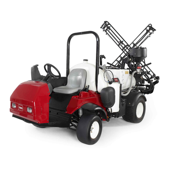
Page 14: Product Overview
Product Overview g033285 Figure 5 1. Roll bar 4. Valve manifolds 7. Section-control cylinder 10. Left section 2. Anti-siphon receptacle 5. Right section 8. Agitation-throttle valve 11. Fuel tank 3. Chemical-tank lid 6. Center section 9. Pressure filter 12. Parking brake... - Page 15 g033286 Figure 6 1. Right section 4. Fresh-water tank 2. Boom-transport cradle 5. Operator’s seat 3. Left section...
-
Page 16: Controls
Controls g204239 Figure 7 1. InfoCenter 6. Range selector 11. Hose-reel-rewind button 16. Supervisor (rate-lockout) (optional) switch 2. Foam-marker switch 7. Choke 12. Agitation switch 17. Master section switch (optional) 3. Pressure gauge 8. Headlight switch 13. Spray-pressure switch 18. Boom-section lift switches 4. - Page 17 Accelerator Pedal Parking Brake The accelerator pedal (Figure 8) gives you the ability The parking brake is a large lever to the left of the to vary the ground speed of the sprayer. Pressing the seat (Figure 9). Engage the parking brake whenever pedal increases ground speed.
- Page 18 Master Section Switch CAUTION Turning with the differential lock on can result The master section switch (Figure 7) is located on the side of the console and to the right of the operator’s in loss of machine control. seat. It allows you to start or stop the spray operation. Do not operate with differential lock on when Press the switch to enable or disable the spray making sharp turns or at high speeds;...
- Page 19 Section-Bypass Shutoff Valve first screen of the InfoCenter. The hour meter starts to function whenever the key is turned to the R The section bypass shutoff valve redirects the fluid position. flow for a section to the tank when you turn off the section.
-
Page 20: Specifications
To ensure optimum performance and continued safety • Ensure that all fluid line connectors are tight and certification of the machine, use only genuine Toro that all hoses are in good condition before applying replacement parts and accessories. Replacement pressure to the system. -
Page 21: Performing Pre-Starting Checks
Chemical Safety • Properly dispose of unused chemicals and chemical containers as instructed by the chemical Chemical substances used in the sprayer system manufacturer and your local codes. may be hazardous and toxic to you, bystanders, and • Chemicals and fumes are dangerous; never enter animals, and they may damage plants, soil, and other the tank or place your head over or in the opening property. -
Page 22: Preparing The Machine
Preparing the Machine Adding Fuel Fuel Specification Checking the Engine Oil Petroleum Use unleaded gasoline with an octane rating of 87 The engine is shipped with oil in the crankcase; fuel or higher ((R+M)/2 rating method). however, the level of oil must be checked before you Use an unleaded-gasoline blend with up to 10% first start the engine and after you have run it. -
Page 23: Breaking In A New Machine
Preparing the Sprayer Selecting a Nozzle Note: Refer to the nozzle-selection guide that is available through your authorized Toro distributor. The turret bodies can accept up to 3 different nozzles. To select the desired nozzle, perform the following: g214212 Stop the sprayer on a level surface, shut off the Figure 13 engine, and engage the parking brake. - Page 24 Pressure Filter Table (cont'd.) Spray Nozzle Screen Mesh Filter Color Code Color Code (flow Size* rate) As required for high Brown viscosity chemicals or solutions or high application rates *The mesh size of the pressure filters in this table are based on spray chemicals or solutions with the viscosity equivalent to water.
- Page 25 g214240 g214246 Figure 16 Figure 17 Mesh size—application rate Mesh size—chemical or solution viscosity 1. Higher application rate 3. Screen mesh size 1. Higher-viscosity chemicals 3. Screen mesh size or solutions 2. Lower application rate 2. Lower-viscosity chemicals or solutions Selecting a Nozzle-Tip Filter When you spray at a higher application rate, consider (Optional)
- Page 26 Filling the Tanks Important: Verify that the proper application rate has been set prior to filling the tank with chemicals. Filling the Fresh-Water Tank Purge the spray system of spray-system Important: Do not use reclaimed water (gray conditioner by running the sections. water) in the fresh-water tank.
- Page 27 Calibrating the Sprayer Flow with a small amount of water to form a slurry before adding it to the tank. Before using the sprayer for the first time, if you Add the remaining water to the tank. change the nozzles, or as needed, calibrate the sprayer flow.
- Page 28 Enter the calibration menu by pressing the between 45 to 152 m (150 to 500 ft). right selection button on the InfoCenter. Note: Toro recommends marking off 152 m Select F by highlighting F (500 ft) for more accurate results.
- Page 29 Set the pump switch to the O position, and turn Adjust the right section-bypass knob (Figure on the agitation. until the pressure reading is at the previously adjusted level (typically 2.75 bar or 40 psi). Press down on the accelerator pedal until you Turn on the right section and turn off the center reach the maximum engine speed, and toggle section.
-
Page 30: Locating The Spray Pump
Press the accelerator pedal to achieve maximum Set the master-section switch to the O engine speed and set the throttle lock. position. Set the 3 section valves to the O position. Increase the engine speed to full throttle and set the throttle lock to the O position. -
Page 31: During Operation
For each machine covered in this Operator’s • Before backing up, look rearward and ensure that Manual, a cab installed by Toro is a ROPS. no one is behind you. Back up slowly. • Do not remove the ROPS from the machine. -
Page 32: Operating The Machine
• • Lower a folding roll bar temporarily only when Always keep the transmission in gear (if applicable) necessary. Do not wear the seat belt when the when you drive the machine down a slope. roll bar is folded down. •... -
Page 33: Using The Differential Lock
pressing the accelerator pedal. Repeat the Pull the parking-brake lever up and back to set it. procedure until the desired speed is attained. Move the range selector out of gear into the position. Important: Always stop the machine before EUTRAL shifting from a forward gear to reverse or Turn the ignition key to the S position. -
Page 34: Positioning The Spray Sections
Note: When the tank is nearly empty, the CAUTION agitation may cause foaming in the tank. Chemicals are hazardous and can cause To prevent this, turn the agitation valve off. personal injury. Alternatively, you can use an anti-foaming agent in the tank. •... -
Page 35: Spraying Tips
Spraying Tips • Do not overlap areas that you have previously sprayed. • Watch for plugged nozzles. Replace all worn or damaged nozzles. • Use the master section switch to stop the spray flow before stopping the sprayer. Once it stops, use the engine-throttle control to hold the engine speed up to keep the agitation running. -
Page 36: Cleaning The Sprayer
Note: The recommendations and instructions that follow assume that the Toro Rinse Kit is not installed. Clean the spray system and any installed spray accessories after each spraying session. To properly clean the spray system, you must rinse it 3 times. - Page 37 Cleaning External Sprayer Components Clean the suction and pressure filters; refer Cleaning the Suction Filter (page 37) Cleaning the Pressure Filter (page 37). Important: If you used wettable powder chemicals, clean the strainer after each tank. Using a garden hose, rinse off the outside of the sprayer with clean water.
- Page 38 Cleaning the Optional Nozzle Filters Park the machine on a level surface, engage the parking brake, shut off the sprayer pump, shut off the engine, and remove the key. Remove the nozzle from the spray turret (Figure 31). g033293 Figure 30 1.
- Page 39 Cleaning the Nozzle Body and Check-Valve Diaphragm Service Interval: Yearly—Clean the nozzle body and check-valve diaphragm. Clean the nozzle body and check-valve diaphragm if you notice that a nozzle(s) is dripping after the section switch(es) is shut off. Rotate the diaphragm cap counterclockwise and remove the cap from the nozzle body (Figure 32).
- Page 40 Important: Use only clean water when cleaning the sprayer. Start the engine and set the spray-pump switch to the O position. Press the accelerator pedal to increase the engine speed. Set the agitation switch to the O position. Allow the conditioner and water solution to circulate for 3 minutes or longer.
-
Page 41: Maintenance
Maintenance Note: Download a free copy of the schematic by visiting www.Toro.com and searching for your machine from the Manuals link on the home page. For additional information about the sprayer system, refer to the sprayer system schematic in Schematics (page 76). -
Page 42: Recommended Maintenance Schedule(S)
• Change the pressure filter. Every 400 hours • Inspect the pump diaphragms and replace if necessary (see an authorized Toro distributor). • Inspect the pump check valves and replace if necessary (see an authorized Toro distributor). • Inspect the nylon pivot bushings. -
Page 43: Daily Maintenance Checklist
Maintenance Service Maintenance Procedure Interval • Change the transaxle/hydraulic fluid and clean strainer. Every 800 hours • Replace the hydraulic filter. • Calibrate the agitation-bypass valve. Yearly • Clean the nozzle body and check-valve diaphragm. Important: Refer to the engine owner’s manual for additional maintenance procedures. Daily Maintenance Checklist Duplicate this page for routine use. -
Page 44: Notation For Areas Of Concern
Notation for Areas of Concern Inspection performed by: Item Date Information CAUTION If you leave the key in the ignition switch, someone could accidently start the engine and seriously injure you or other bystanders. Remove the key from the ignition and disconnect the wire(s) from the spark plug(s) before you perform any maintenance. -
Page 45: Lubrication
Lubrication Greasing the Machine Service Interval: Every 100 hours/Yearly (whichever comes first)—Lubricate all grease fittings. Grease Type: No. 2 lithium grease g216324 Refer Figure 36 for the grease-point locations. g216476 Figure 36 Wipe the grease fitting clean so that you do not force dirt or debris into the bearing or bushing. -
Page 46: Greasing The Section Hinges
Greasing the Section Engine Maintenance Hinges Engine Safety Service Interval: Every 100 hours Shut off the engine before checking the oil or adding Important: If the section hinge is washed with oil to the crankcase. water, clear all water and debris from the hinge assembly and apply fresh grease. -
Page 47: Servicing The Engine Oil
1. Foam element 2. Oil • Alternate oil: SAE 5W30 (below 32°F) Squeeze the element to distribute the oil. Toro Premium Engine Oil is available from your distributor in either 10W30 or 5W30 viscosity. See the Parts Catalog for part numbers. - Page 48 Checking the Engine Oil CAUTION Components under the seat are hot if the Service Interval: Before each use or daily sprayer has been running. If you touch Every 400 hours/Yearly (whichever comes first) hot components, you may be burned. The engine is shipped with oil in the crankcase; Allow the sprayer to cool before however, you must check the level of oil before you performing maintenance or touching...
-
Page 49: Changing The Spark Plugs
Checking the Spark Plugs tighten the filter an additional 1/2 turn (Figure 43). Look at the center of the spark plugs (Figure 45). Fill the crankcase with the correct type of new Note: If you see a light brown or gray coating oil;... -
Page 50: Fuel System Maintenance
Servicing the Carbon Fuel System Canister Maintenance Checking the Air Filter for the Replacing the Fuel Filter Carbon Canister Service Interval: Every 100 hours—Replace the fuel Service Interval: After the first 50 hours filter. Every 200 hours Every 400 hours/Yearly (whichever comes first)—Inspect the fuel lines. -
Page 51: Draining The Fuel Tank
Draining the Fuel Tank Electrical System Maintenance Service Interval: Every 400 hours/Yearly (whichever comes first) Drain and clean the fuel tank if the fuel system Electrical System Safety becomes contaminated or if you plan to store the • machine for an extended period. Use fresh, clean fuel Disconnect the battery before repairing the to flush out the tank. - Page 52 Important: The battery is located on the right side of the Always keep the battery retainer machine behind the pump (Figure 48). in place to protect and secure the battery. Disconnect the negative (black) ground cable Connect the positive (red) cable to the positive from the battery post.
-
Page 53: Drive System Maintenance
Charging the Battery Drive System Maintenance WARNING Charging the battery produces gasses that can explode. Inspecting the Wheels and Never smoke near the battery and keep sparks Tires and flames away from battery. Service Interval: Before each use or daily—Check Important: Always keep the battery fully charged the tire pressure. -
Page 54: Adjusting The Front Wheel Toe-In
g002006 Figure 50 1. Tire centerline—back 4. Fixture 2. Tire centerline—front 5. Axle-centerline distance g002425 Figure 49 3. Axle centerline 6. 15 cm (6 inches) ruler 1. Differential-lock cable 3. Spring 2. Transaxle bracket 4. 0.25 to 1.5 mm (0.01 to If the measurement does not fall within the 0.06 inch) gap specified range, loosen the jam nuts at both... -
Page 55: Brake Maintenance
Brake Maintenance Adjusting the Parking Brake Checking the Brake Fluid Service Interval: Every 200 hours—Check the parking brake. The brake-fluid reservoir is shipped from the factory filled with DOT 3 brake fluid. Check the level before Remove the plastic grip. starting the engine each day. -
Page 56: Hydraulic System Maintenance
Hydraulic System Maintenance Hydraulic System Safety • Seek immediate medical attention if fluid is injected into skin. Injected fluid must be surgically removed within a few hours by a doctor. • Safely relieve all pressure in the hydraulic system before performing any work on it. •... -
Page 57: Replacing The Hydraulic Filter
Replacing the Hydraulic Filter Service Interval: After the first 8 hours Every 800 hours/Yearly (whichever comes first) Use the Toro replacement filter (Part No. 54-0110). Important: Use of any other filter may void the warranty on some components. Position the sprayer on a level surface, set... -
Page 58: Spray System Maintenance
Spray System Maintenance Inspecting the Hoses Service Interval: Every 200 hours—Inspect all hoses and connections for damage and proper attachment. Examine each hose in the spray system for cracks, leaks or other damage. At the same time, inspect the connections and fittings for similar damage. Replace any worn or damaged hoses and fittings. -
Page 59: Changing The Nozzle Filter
(see an authorized (Figure 60). Toro distributor). Every 400 hours/Yearly (whichever comes first)—Inspect the pump check valves and replace if necessary (see an authorized Toro distributor). Note: The following machine components are considered parts subject to consumption through use... -
Page 60: Inspecting The Nylon Pivot Bushings
(Figure 62). Have an authorized Toro distributor check following Install the boom and pivot bracket assembly into internal pump components for damage: the center frame, aligning the holes (Figure 62). -
Page 61: Cleaning
Cleaning Cleaning the Flow Meter Service Interval: Every 200 hours/Yearly (whichever comes first) (more often when using wettable powders). Thoroughly rinse and drain the entire spraying system. Remove the flow meter from the sprayer and flush it with clean water. Remove the retainer ring on the upstream side (Figure 65). -
Page 62: Cleaning The Sprayer Valves
Cleaning the Sprayer Removing the Valve Actuator Position the sprayer on a level surface, engage Valves the parking brake, shut off the pump, shut off the • engine, and remove the key. To clean the rate-control valve, refer to the following sections: Remove the 3-pin connector of the valve actuator from the 3-socket connector of the... - Page 63 Removing the Rate-Control-Manifold Valve Remove the clamps and gaskets that secure the manifold for the rate-control valve (Figure 67). Note: Retain the clamp(s) and gasket(s) for installation in Installing the Rate Control Manifold Valve (page 68). g033313 Figure 68 1. Flanged-head bolt 4.
- Page 64 Removing the Master-Section-Manifold Valve Remove the clamps and gaskets that secure the manifold for the master-section valve (Figure to the master-section-bypass valve, agitation valve, and master-section-manifold valve (at the end of the hose for the flow meter). Note: Retain the clamp(s) and gasket(s) for installation in Installing the Master-Section-Manifold Valve (page...
- Page 65 Remove the retainers that secure the outlet fitting to the section-valve manifold and the valve manifold to the bypass fitting (Figure 74). g033309 Figure 72 1. Flanged-head bolt 3. Valve mount 2. Manifold (master-section 4. Flanged locknut valve) Removing the Section-Manifold Valve Remove clamps and gaskets that secure the manifold for the section valve...
- Page 66 g028243 Figure 77 Agitation Valve Manifold g028239 Figure 75 1. Stem retainer 7. Back seating O-ring (0.676 x 0.07 inch) 1. Bypass fitting 2. Section-valve manifold 2. Valve stem 8. Valve-seat ring 3. Stem port 9. Manifold body 4. Stem-capture retainer 10.
- Page 67 Assembling the Manifold Valve Operator supplied material: Clear silicone grease. Important: Use only silicone grease when assembling the valve. Check the condition of the outlet fitting O-rings (section valve manifold only), end cap O-rings, back seating O-rings, and ball seat for damage or wear (Figure 77 Figure...
- Page 68 Installing the Rate Control Assemble the rate control valve manifold, gasket, and agitation-valve manifold with a Manifold Valve flange clamp and tighten by hand (Figure 80A). Align a gasket between the flanges of the rate Assemble the rate control valve to the valve control valve manifold and the pressure filter mount with the 2 flanged-head bolts and 2 head...
- Page 69 Secure the end-cap fitting to the outlet fitting by inserting a retainer into the socket of the outlet fitting (Figure 81C). Assemble the agitation valve to the valve mount with the flanged-head bolt and flanged locknut that you removed in step Removing the Agitation-Manifold Valve (page 63) and torque...
- Page 70 Installing the Section Manifold Assemble the master-section-valve manifold, gasket, and master-section-bypass valve with a Valve clamp tightened by hand (Figure 82A). Insert the upper end-cap fitting of the manifold Align the flange of the master-section-valve valve into the bypass fitting (Figure 83A).
-
Page 71: Storage
Storage For the left or right boom section valves, assemble the valves to the valve mount with the flanged-head bolt and flanged locknut Preparing the Sprayer that you removed in step Removing the Section-Manifold Valve (page 65) and torque the System nuts and bolts to 10 to 12 N∙m (90 to 110 in-lb). -
Page 72: Performing The Service Procedures
A fuel stabilizer/conditioner is most Paint all scratched or bare metal surfaces. Paint effective when mixed with fresh gasoline is available from your authorized Toro distributor. and used at all times. Store the machine in a clean, dry garage or Run the engine to distribute conditioned fuel storage area. -
Page 73: Troubleshooting
3. Correct or replace fuse. 4. The battery is discharged. 4. Charge or replace the battery. 5. The safety-interlock system is 5. Contact your authorized Toro malfunctioning. distributor. 6. A starter or starter solenoid is broken. 6. Contact your authorized Toro distributor. - Page 74 3. A spark plug is damaged or broken. 3. Replace the spark plug. 4. Carburetor idle passages are plugged. 4. Contact your authorized Toro distributor. 5. The idle speed adjusting screw is 5. Contact your authorized Toro incorrectly set.
- Page 75 3. Repair or replace the hose. 4. A section bypass is improperly 4. Adjust the section bypass. adjusted. 5. There are damaged section valve. 5. Contact your authorized Toro distributor. 6. The electrical system is damaged. 6. Contact your authorized Toro distributor.
-
Page 76: Schematics
Schematics g028078 Sprayer System Schematic (Rev. DWG 125-0698 Rev B) - Page 77 Notes:...
- Page 78 The Way Toro Uses Information Toro may use your personal information to process warranty claims, to contact you in the event of a product recall and for any other purpose which we tell you about. Toro may share your information with Toro's affiliates, dealers or other business partners in connection with any of these activities. We will not sell your personal information to any other company.
- Page 79 While the exposure from Toro products may be negligible or well within the “no significant risk” range, out of an abundance of caution, Toro has elected to provide the Prop 65 warnings. Moreover, if Toro does not provide these warnings, it could be sued by the State of California or by private parties seeking to enforce Prop 65 and subject to substantial penalties.
- Page 80 Countries Other than the United States or Canada Customers who have purchased Toro products exported from the United States or Canada should contact their Toro Distributor (Dealer) to obtain guarantee policies for your country, province, or state. If for any reason you are dissatisfied with your Distributor's service or have difficulty obtaining guarantee information, contact the Toro importer.