Toro Multi Pro 1750 Service Manual
Hide thumbs
Also See for Multi Pro 1750:
- Operator's manual (76 pages) ,
- Installation instructions manual (65 pages) ,
- Operator's manual (32 pages)
Table of Contents
Advertisement
Quick Links
Advertisement
Chapters
Table of Contents
Troubleshooting

Related Manuals for Toro Multi Pro 1750


Summary of Contents for Toro Multi Pro 1750
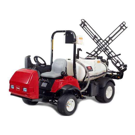
- Page 1 Form No. 15215SL Rev A ® Multi Pro 1750 Original Instructions (EN)
- Page 2 THE TORO COMPANY 2018 This document and all information contained herein is the sole property of The Toro Company (and/or its affiliated companies). No intellectual property rights are granted by the delivery of this document or the disclosure of its content. This document shall not be...
- Page 3 Reader Comments The Toro Company Technical Assistance Center maintains a continuous effort to improve the quality and usefulness of its publications. To do this effectively, we encourage user feedback. Please comment on the completeness, accuracy, organization, usability, and readability of this manual by an e-mail to servicemanuals@toro.com...
- Page 4 NOTES...
- Page 5 The Toro Company reserves the right to change product specifications or this publication without notice. IMPORTANT: The IMPORTANT notice will give im- portant instructions which must be followed to pre- vent damage to systems or components on the machine.
- Page 6 This page is intentionally blank. Multi Pro 1750...
- Page 7 Component Testing ......5 − 30 Service and Repairs ..... . . 5 − 65 Multi Pro 1750...
- Page 8 This page is intentionally blank. Multi Pro 1750...
-
Page 9: Table Of Contents
..... SAFETY AND INSTRUCTION DECALS ..Multi Pro 1750 Page 1 − 1 Safety... -
Page 10: Safety Instructions
Safety Instructions The Multi Pro 1750 Turf Sprayer is designed and tested to offer safe service when operated and maintained WARNING properly. Although hazard control and accident preven- tion are partially dependent upon the design and config- To reduce the potential for injury or death, uration of the machine, these factors are also comply with the following safety instructions. -
Page 11: Maintenance And Service
16.To assure optimum performance and continued 7. Before disconnecting or performing any work on the safety of the machine, use genuine Toro replacement hydraulic system, all pressure in the system must be re- parts and accessories. Replacement parts and acces- lieved. -
Page 12: Jacking Instructions
Safety and Instruction Decals Numerous safety and instruction decals are affixed to the Multi Pro 1750. If any decal becomes illegible or damaged, install a new decal. Decal part numbers are listed in your Parts Catalog. Order replacement decals from your Authorized Toro Distributor. - Page 13 ......Product Records Insert Operator’s Manual and Parts Catalog for your Multi Pro 1750 at the end of this chapter. Refer to Opera- tor’s Manual for recommended maintenance intervals. Additionally, insert Installation Instructions, Operator’s...
-
Page 14: Product Records
Equivalents and Conversions 0.09375 Product Records and Maintenance Page 2 − 2 Multi Pro 1750... -
Page 15: Torque Specifications
For critical applications, as determined reduced by 25% for lubricated fasteners to achieve by Toro, either the recommended torque or a torque that the similar stress as a dry fastener. Torque values may is unique to the application is clearly identified and spe- also have to be reduced when the fastener is threaded cified in this Service Manual. -
Page 16: Standard Torque For Dry, Zinc Plated And Steel Fasteners (Inch Series Fasteners)
+ 10% of the nominal torque value. Thin The specific torque value should be determined based height nuts include jam nuts. Product Records and Maintenance Page 2 − 4 Multi Pro 1750... -
Page 17: Standard Torque For Dry, Zinc Plated And Steel Fasteners (Metric Fasteners)
NOTE: Torque values may have to be reduced when SAE J1199. The tolerance is approximately + 10% of the installing fasteners into threaded aluminum or brass. nominal torque value. The specific torque value should be determined based Multi Pro 1750 Page 2 − 5 Product Records and Maintenance... -
Page 18: Other Torque Specifications
All torque values are based on non−lubri- cated fasteners. Conversion Factors in−lb X 11.2985 = N−cm N−cm X 0.08851 = in−lb ft−lb X 1.3558 = N−m N−m X 0.7376 = ft−lb Product Records and Maintenance Page 2 − 6 Multi Pro 1750... - Page 19 ........KOHLER ENGINE SERVICE MANUAL Multi Pro 1750 Page 3 − 1...
-
Page 20: Specifications
Oil Pump Gear driven trochoid type Crankcase Oil Capacity 2.1 U.S. qt (2.0 liters) with filter Starter 12 VDC Alternator/Regulator 12 VDC 25 AMP Dry Weight (approximate) 94 lb (43 kg) Kohler Gasoline Engine Page 3 − 2 Multi Pro 1750... -
Page 21: General Information
This chapter gives information about specifications and tools are described in the Kohler Engine Service Manu- repair of the Kohler engine used in the Multi Pro 1750. al. The use of some specialized test equipment is ex- plained. However, the cost of the test equipment and the... -
Page 22: Special Tools
Special Tools Order special tools from your Toro Distributor. Clutch Alignment Tool Use clutch alignment tool to align clutch friction disk to engine flywheel before tightening pressure plate cap screws. Toro Part Number: TOR6002 Figure 1 Kohler Gasoline Engine Page 3 − 4... -
Page 23: Troubleshooting
Clutch noisy. Improper installation of clutch cover assembly. Excessive wear of clutch disc facing. Worn clutch disc spline. Weak or broken clutch torsion spring. Damaged pilot bushing. Damaged release bearing. Multi Pro 1750 Page 3 − 5 Kohler Gasoline Engine... - Page 24 Oil adhered to clutch disc facing. Uneven height of diaphragm spring. Weak or damaged clutch torsion spring. Damaged pressure plate or flywheel. Damaged clutch release bearing. Loose or worn front wheel bearings. Kohler Gasoline Engine Page 3 − 6 Multi Pro 1750...
-
Page 25: Adjustments
C. Tighten jam nut. Recheck low idle speed. 9. Make sure the accelerator pedal contacts the throttle home switch and comes to rest against the hard pedal stop when released. Multi Pro 1750 Page 3 − 7 Kohler Gasoline Engine... -
Page 26: Adjust Choke Cable
Reposi- tion cable to allow correct choke operation. Secure Figure 3 choke cable clamp. 1. Choke cable 2. Cable clamp 6. Verify choke operation and assemble air cleaner. Kohler Gasoline Engine Page 3 − 8 Multi Pro 1750... -
Page 27: Adjust Clutch Cable
Figure 4 1. Clutch cable 3. Bulkhead nuts (2) 2. Return spring 2.4 to 2.6 in (60 to 66 mm) Figure 5 1. Clutch pedal 3. Pedal stop/switch mount 2. Switch Multi Pro 1750 Page 3 − 9 Kohler Gasoline Engine... -
Page 28: Service And Repairs
IMPORTANT: Never operate engine without the blower housing installed. Engine overheating and damage will result. 4. Make sure debris screen and blower housing are re- installed to the engine if removed. Kohler Gasoline Engine Page 3 − 10 Multi Pro 1750... - Page 29 This page is intentionally blank. Multi Pro 1750 Page 3 − 11 Kohler Gasoline Engine...
-
Page 30: Fuel System
19. Flat washer (2) 6. Fuel tank mount 13. Vapor hose (check valve to engine) 20. Cap screw (2) 7. Flange nut (5) 14. Carbon canister 21. Cap screw (2) Kohler Gasoline Engine Page 3 − 12 Multi Pro 1750... - Page 31 Disconnect fuel hoses from fuel standpipe and rollover valve. Plug fuel hoses to prevent leakage or contami- nant entry. 4. Remove fuel tank from machine. 5. Remove components from fuel tank as needed (Fig. 8). Multi Pro 1750 Page 3 − 13 Kohler Gasoline Engine...
-
Page 32: Carbon Canister
Gasoline is flammable. Use caution when stor- The fuel tank on Multi Pro 1750 machines uses a non− ing or handling it. Do not smoke while filling the vented fuel cap. To connect the tank to the evaporative fuel tank. - Page 33 This page is intentionally blank. Multi Pro 1750 Page 3 − 15 Kohler Gasoline Engine...
-
Page 34: Exhaust System
5. Exhaust pipe 12. Muffler Clamp 19. Muffler bracket 6. Hex head screw (8) 13. Muffler mount 20. Exhaust support bracket 7. Hanger bracket 14. R−Clamp 21. Hex head screw Kohler Gasoline Engine Page 3 − 16 Multi Pro 1750... - Page 35 5. Install the spray tank assembly if previously re- on engine. Remove exhaust manifold from the engine. moved (see Spray Tank in Chapter 6 − Spray Tank in this manual). 6. Remove and discard exhaust gaskets from engine. Multi Pro 1750 Page 3 − 17 Kohler Gasoline Engine...
-
Page 36: 11. Engine And Pump Mounting Plate
(see Spray Pump in Chapter 6 − Spray Pump in this manual and Engine in this chapter). Kohler Gasoline Engine Page 3 − 18 Multi Pro 1750... - Page 37 (stud). D. Disconnect battery negative (−) cable and ma- chine wire harness ground at engine base (Fig. 11). E. Disconnect wire harness connector at at spray pump electric clutch. Multi Pro 1750 Page 3 − 19 Kohler Gasoline Engine...
- Page 38 C. Carefully remove the engine and pump mounting plate assembly from the machine. Kohler Gasoline Engine Page 3 − 20 Multi Pro 1750...
- Page 39 E. Connect wire harness connector at spray pump electric clutch. 8. Connect fuel line to the fuel pump on engine. Con- nect evaporative system vapor hose to engine intake manifold (left side of engine). Multi Pro 1750 Page 3 − 21 Kohler Gasoline Engine...
-
Page 40: Engine
14. Button head screw (4) 22. Flat washer (2) 7. Lock nut (2) 15. Lock nut 23. Hex head screw (2) 8. Flat washer (2) 16. Sprocket adaptor 24. Engine and pump mounting plate Kohler Gasoline Engine Page 3 − 22 Multi Pro 1750... - Page 41 2. Install engine clutch assembly if removed (see Clutch in this chapter). 3. Install throttle bracket assembly if removed (Fig. 17). Tighten mounting screws from 65 to 85 in−lb (7.4 to 9.6 N−m). Multi Pro 1750 Page 3 − 23 Kohler Gasoline Engine...
- Page 42 5. Carefully lift engine onto the engine and pump mounting plate and secure with four (4) flange head screws and flange nuts. Tighten fasteners from 27 to 33 ft−lb (37 to 44 N−m). Kohler Gasoline Engine Page 3 − 24 Multi Pro 1750...
- Page 43 This page is intentionally blank. Multi Pro 1750 Page 3 − 25 Kohler Gasoline Engine...
- Page 44 11. Alignment pin (3) 24. Release shaft 37. Exhaust support bracket 12. Clutch disc 25. Flange head screw (3) (machine serial no 314000001 thru 13. Pressure plate assembly 26. Release guide 31400500) Kohler Gasoline Engine Page 3 − 26 Multi Pro 1750...
- Page 45 Locate and retrieve flywheel key. 11. If necessary, remove four (4) hex head screws, lock washers, and flat washers, and remove adapter plate (item 1) from engine. Multi Pro 1750 Page 3 − 27 Kohler Gasoline Engine...
- Page 46 3. Install new pilot bearing (item 10) in flywheel. 9. Install exhaust system (see Exhaust System in this 4. Thoroughly clean clutch contact surface of flywheel chapter). and pressure plate with solvent. Kohler Gasoline Engine Page 3 − 28 Multi Pro 1750...
- Page 47 (3) flange head screws. Tighten screws from 90 to 120 in−lbs (10 to 12 N−m). Apply anti seize lubricant to shoulder of release guide, output shaft splines, and out- put shaft pilot bearing surface. Multi Pro 1750 Page 3 − 29 Kohler Gasoline Engine...
- Page 48 This page is intentionally blank. Kohler Gasoline Engine Page 3 − 30 Multi Pro 1750...
- Page 49 ......Boom Lift Cylinder Service ....DANFOSS STEERING UNIT TYPE OSPM SERVICE MANUAL Multi Pro 1750 Page 4 − 1 Hydraulic System...
-
Page 50: Specifications
Rotary valve steering unit with power beyond (Sauer Danfoss series OSPM) Displacement (per revolution) 4.3 in (70 cc) Hydraulic Filter Spin−on cartridge type Hydraulic Reservoir In transaxle Hydraulic Oil Dexron III ATF (See Operator’s Manual) Hydraulic System Page 4 − 2 Multi Pro 1750... - Page 51 This page is intentionally blank. Multi Pro 1750 Page 4 − 3 Hydraulic System...
-
Page 52: General Information
3. Turn ignition key to the STOP position and rotate in the boom cradles. Shut engine off. steering wheel in both directions to relieve hydraulic pressure in the steering circuit. Hydraulic System Page 4 − 4 Multi Pro 1750... -
Page 53: Hydraulic Hoses
If the hose has an elbow at one end, tighten the swivel nut on that end before tightening the nut on the straight end of the hose. For additional hydraulic hose information, refer to Toro Service Training Book, Hydraulic Hose Servicing (Part Number 94813SL). - Page 54 85 to 105 ft−lb (116 to 142 N−m) 1 7/16 − 12 110 to 136 ft−lb (150 to 184 N−m) 1 11/16 − 12 140 to 172 ft−lb (190 to 233 N−m) Figure 3 Hydraulic System Page 4 − 6 Multi Pro 1750...
-
Page 55: Hydraulic Fittings
202 to 248 ft−lb (274 to 336 N−m) 121 to 149 ft−lb (165 to 202 N−m) 1 5/8 − 12 247 to 303 ft−lb (335 to 410 N−m) 149 to 183 ft−lb (202 to 248 N−m) Figure 5 Multi Pro 1750 Page 4 − 7 Hydraulic System... - Page 56 F.F.F.T (Step 4). If port material is aluminum, tighten fitting to 60% of listed F.F.F.T. Hydraulic System Page 4 − 8 Multi Pro 1750...
-
Page 57: Hydraulic Schematic
Hydraulic Schematic Multi Pro 1750 Page 4 − 9 Hydraulic System... -
Page 58: Hydraulic Flow Diagrams
Hydraulic Flow Diagrams Figure 8 Hydraulic System Page 4 − 10 Multi Pro 1750... -
Page 59: Steering Circuit
Fluid leaving the cylinder flows back through the steering control spool valve, then to the oil filter and returns to the transaxle. The steering control valve returns to the neutral position when turning is completed. Multi Pro 1750 Page 4 − 11 Hydraulic System... - Page 60 Figure 9 Hydraulic System Page 4 − 12 Multi Pro 1750...
-
Page 61: Spray Boom Lift/Lower Circuit
(SOLENOIDS S1, S2 AND S3 ALL DE−ENERGIZED) gized. The de−energized valve (S1) allows hydraulic Figure 10 flow to return to tank through the manifold. The boom lift Multi Pro 1750 Page 4 − 13 Hydraulic System... -
Page 62: Special Tools
Special Tools Order the following special tools from your Toro Distributor. Hydraulic Pressure Test Kit Use to take various pressure readings for diagnostic tests. Quick disconnect fittings provided attach directly to mating fittings on machine test ports without tools. A high pressure hose is provided for remote readings. - Page 63 Figure 13 Hydraulic Test Fitting Kit This kit includes a variety of O−ring Face Seal fittings to TORO TEST FITTING KIT (TOR4079) enable the connection of test gauges into the system. The kit includes: tee’s, unions, reducers, plugs, caps and male test fittings.
-
Page 64: Troubleshooting
Steering and spray booms inoperative Hydraulics enable valve solenoid coil or circuit wiring has electrical problem (see Chapter 5 − Electrical System in this manual). Hydraulic pump is worn or damaged Hydraulic System Page 4 − 16 Multi Pro 1750... - Page 65 Boom lift control manifold check valve for affected boom (PC1 or PC2) is sticking or damaged. Boom lift control manifold orifice for affected boom is plugged or damaged. Affected lift cylinder is worn or damaged. Multi Pro 1750 Page 4 − 17 Hydraulic System...
- Page 66 Cartridge valve seals are leaking in boom lift control perfect seal. A spray boom may eventually lower manifold. during storage. Lift cylinder for affected boom leaks internally. Hydraulic hoses to lift control cylinder for affected boom are incorrectly installed. Hydraulic System Page 4 − 18 Multi Pro 1750...
-
Page 67: Testing
5. When using a hydraulic tester with pressure and flow capabilities, open load valve completely in the hydraulic tester to minimize the possibility of damaging compo- nents. Multi Pro 1750 Page 4 − 19 Hydraulic System... - Page 68 9. Check control linkages for improper adjustment, machine parts from contacting and damaging the hoses binding, or broken parts. or tester. 10.All hydraulic tests should be made with the hydraulic fluid at normal operating temperature. Hydraulic System Page 4 − 20 Multi Pro 1750...
-
Page 69: Hydraulic Pump Flow And Relief Pressure Test
0.26 25 PSI 1000 PSI (open) 3400 / 1400 RPM FROM 27 HP LIFT MANIFOLD FILTER Working Pressure 100 Mesh Screen Low (Charge) Pressure Return or Suction TRANSAXLE/RESERVOIR Flow Figure 15 Multi Pro 1750 Page 4 − 21 Hydraulic System... - Page 70 10.After testing is completed, disconnect tester from lows). steering pump and hose. Reconnect hose to the pump. Check and adjust hydraulic oil level. C. Hydraulic pump needs to be repaired or replaced. Hydraulic System Page 4 − 22 Multi Pro 1750...
- Page 71 This page is intentionally blank. Multi Pro 1750 Page 4 − 23 Hydraulic System...
-
Page 72: Steering Control Valve And Steering Cylinder Test
0.26 1000 PSI (open) 25 PSI 3400 / 1400 RPM 27 HP FROM LIFT MANIFOLD 100 Mesh Screen FILTER Working Pressure Low (Charge) Pressure Return or Suction TRANSAXLE/RESERVOIR Flow Figure 17 Hydraulic System Page 4 − 24 Multi Pro 1750... - Page 73 Valve Service in the Service and Repairs section of this steering cylinder (Fig. 18). Plug the end of the hose. chapter). 7. After testing is completed, reconnect hose to the steering cylinder. Check and adjust hydraulic oil level. Multi Pro 1750 Page 4 − 25 Hydraulic System...
-
Page 74: Service And Repairs
If fluid is in- jected into the skin, it must be surgically re- moved within a few hours by a doctor familiar with this type of injury. Gangrene may result from such an injury. Hydraulic System Page 4 − 26 Multi Pro 1750... -
Page 75: Flushing The Hydraulic System
14.Shut off engine and check for oil leaks. Check oil lev- el in transaxle and add correct oil if necessary. 15.Operate the machine for two (2) hours under normal operating conditions. Multi Pro 1750 Page 4 − 27 Hydraulic System... -
Page 76: Hydraulic Pump
5. Hose clamp 12. Pump hub 19. Spacer 6. Suction hose 13. Rubber coupler 20. Flat washer (2) 7. Lock nut (2) 14. Button head screw (4) 21. Hex head screw (2) Hydraulic System Page 4 − 28 Multi Pro 1750... - Page 77 Connect suction hose and swivel connector at hy- draulics enable valve to gear pump fittings (see Hydrau- lic Hose and Tube Installation in this chapter). 7. Check fluid level in transaxle and adjust as required. Multi Pro 1750 Page 4 − 29 Hydraulic System...
-
Page 78: Hydraulic Pump Service
3. Clamp mounting flange of pump in a vise with the shaft end down. 4. Loosen four (4) socket head screws that secure the rear cover. Figure 24 5. Remove pump from the vise. Remove socket head screws and washers. Hydraulic System Page 4 − 30 Multi Pro 1750... - Page 79 2. Gear shaft 5. Thrust plate cates need for replacement. 3. Gear teeth B. Gear teeth should be free of excessive scoring and wear. Any broken or nicked gear teeth must be replaced. Multi Pro 1750 Page 4 − 31 Hydraulic System...
- Page 80 If input shaft binds, disassemble pump and 8. Install dowel pins in body. repeat assembly process. IMPORTANT: Do not dislodge O−rings, pressure 17.Remove pump from vise. seals or back−up seals during final assembly. Hydraulic System Page 4 − 32 Multi Pro 1750...
- Page 81 This page is intentionally blank. Multi Pro 1750 Page 4 − 33 Hydraulic System...
-
Page 82: Steering Control Valve
12. Steering control valve 3. Flat washer 8. Cable tie (4) 13. Cap screw (3) 4. Steering wheel 9. Dust cover 14. Flat washer (3) 5. Panel fastener (10) 10. Hydraulic hoses (5) Hydraulic System Page 4 − 34 Multi Pro 1750... - Page 83 Using labels placed during removal, con- machine to service. nect hydraulic hoses to steering control valve (Fig. 28). Tighten hose connections (see Hydraulic Hose and Tube Installation in this chapter). Multi Pro 1750 Page 4 − 35 Hydraulic System...
-
Page 84: Steering Control Valve Service
20. Screw/fitting (ports P, T and E) 7. Ball stop 14. Distribution plate NOTE: For service of the steering control valve, see the Sauer/Danfoss Steering Unit Type OSPM Service Manual at the end of this chapter. Hydraulic System Page 4 − 36 Multi Pro 1750... - Page 85 This page is intentionally blank. Multi Pro 1750 Page 4 − 37 Hydraulic System...
-
Page 86: Steering Cylinder
80 to 90 ft−lb (109 to 122 N−m) RIGHT FRONT Figure 30 1. Steering cylinder 3. Retaining ring (2) 5. Cotter pin (2) 2. Ball joint (2) 4. Slotted hex nut (2) Hydraulic System Page 4 − 38 Multi Pro 1750... - Page 87 O−rings onto fittings. Install fittings into cylinder openings using marks made during the re- moval process to properly orientate fittings. Tighten fit- tings (see Hydraulic Fitting Installation in this chapter). Multi Pro 1750 Page 4 − 39 Hydraulic System...
-
Page 88: Steering Cylinder Service
7. Seal 12. Backup ring (2) 3. Shaft − front 8. Wear ring 13. Seal (2) 4. Roll pin 9. Head (2) 14. Retaining ring (2) 5. Piston 10. Dust seal (2) Hydraulic System Page 4 − 40 Multi Pro 1750... - Page 89 2. Carefully inspect internal surface of barrel for dam- C. Apply silicone sealer to tube access slot. age (deep scratches, out−of−round, etc.). Multi Pro 1750 Page 4 − 41 Hydraulic System...
-
Page 90: Hydraulics Enable Valve
See Hydraulic Solenoid Valve Coils in Chapter 5 − Elec- trical System for information on testing the solenoid coil. 25 ft−lb (34 N−m) Figure 34 1. Nut 4. Seal kit 2. Solenoid coil 5. Manifold 3. Cartridge valve Hydraulic System Page 4 − 42 Multi Pro 1750... - Page 91 This page is intentionally blank. Multi Pro 1750 Page 4 − 43 Hydraulic System...
-
Page 92: Boom Lift Control Manifold
(machine serial no 315000001 & up) 12. Lift cylinder (2) 18. Stiffener plate 6. Cap screw (2) 13. Pivot pin (2) (machine serial no 314000001 thru 7. Flange nut (6) 14. Flange head screw (2) 314000999) Hydraulic System Page 4 − 44 Multi Pro 1750... - Page 93 6. Check fluid level in transaxle and adjust as required (see Operator’s Manual). 7. If necessary, remove fittings and flow control orifices from control manifold and discard O−rings (Fig. 36). Multi Pro 1750 Page 4 − 45 Hydraulic System...
-
Page 94: Boom Lift Control Manifold Service
4. Coil spacer (2) 9. Solenoid coil − S3 (LH boom raise) 14. Check valve − CV2 (PC2 port) 5. Solenoid valve − S3 (LH boom) 10. Solenoid coil − S3 (LH boom lower) Hydraulic System Page 4 − 46 Multi Pro 1750... - Page 95 (e.g. a hydraulic problem exists). draulic lines, cartridge valves or plugs from lift control manifold. If booms are not fully raised as manifold components are loosened, booms may drop unexpectedly. Multi Pro 1750 Page 4 − 47 Hydraulic System...
-
Page 96: Cartridge Valve Service
60 in−lb (6.8 N−m). Use eye protection such as goggles when using 3. If problems still exist after assembly, remove valve compressed air. and clean again or replace valve. Hydraulic System Page 4 − 48 Multi Pro 1750... - Page 97 This page is intentionally blank. Multi Pro 1750 Page 4 − 49 Hydraulic System...
-
Page 98: Boom Lift Cylinders
Figure 38 1. Hydraulic boom lift cylinder (2) 4. Hydraulic hoses 6. Flange nut (2) 2. Clevis pin (2) 5. Pivot pin (2) 7. Flange head screw (2) 3. Cotter pin (2) Hydraulic System Page 4 − 50 Multi Pro 1750... - Page 99 3. Disconnect hydraulic hoses from boom lift cylinder. should be no fluid leaks. Allow hoses to drain into a suitable container. 4. Put caps or plugs on disconnected hoses and cylin- der ports to prevent contamination. Multi Pro 1750 Page 4 − 51 Hydraulic System...
-
Page 100: Boom Lift Cylinder Service
11. O−ring 2. Jam nut 7. Shaft seal 12. Seal 3. Shaft 8. Back−up ring 13. Piston 4. Internal collar 9. O−ring 14. Lock nut 5. Head 10. Steel ring 15. Barrel Hydraulic System Page 4 − 52 Multi Pro 1750... - Page 101 Dexron III ATF. Slide piston, shaft and head assembly into the barrel being careful to not damage the seals. 6. Install internal collar (item 4) with a spanner wrench to secure head into the barrel. Multi Pro 1750 Page 4 − 53 Hydraulic System...
- Page 102 This page is intentionally blank. Hydraulic System Page 4 − 54 Multi Pro 1750...
- Page 103 Traction Speed Sensor ..... Toro Electronic Controller (TEC) ....
-
Page 104: General Information
Electrical Drawings The electrical schematics and wire harness drawings for the Multi Pro 1750 are located in Chapter 10 − Electrical Drawings. Toro Electronic Controller (TEC) Multi Pro 1750 machines use a single Toro Electronic... -
Page 105: Special Tools
The multimeter can test electrical components and cir- cuits for current, resistance or voltage. Obtain this tool locally. NOTE: Toro recommends the use of a DIGITAL Volt− Ohm−Amp multimeter when testing electrical circuits. The high impedance (internal resistance) of a digital me- ter in the voltage mode will make sure that excess cur- rent is not allowed through the meter. - Page 106 Spark Tester The spark tester can be used to test magneto ignitions on gasoline engines. The spark tester determines if igni- tion is present. Toro Part Number: TOR4036 Figure 4 Battery Hydrometer Use the Battery Hydrometer when measuring specific gravity of battery electrolyte. Obtain this tool locally.
-
Page 107: Traction Speed Sensor Test Harness
7. If frequency is not registered, is erratic, or does not increase when increasing speed, remove and replace the speed sensor. See Traction Speed Sensor in the Service and Repairs section of this chapter. Multi Pro 1750 Electrical System Page 5 − 5... -
Page 108: Flow Meter Sensor Test Harness
A. Thread jam nut against sensor hex head. B. Thread sensor into flow meter body until bottom of sensor jam nut is 0.38 in. (9.6 mm) form flow meter body. Electrical System Multi Pro 1750 Page 5 − 6... -
Page 109: Infocenter Display
Use the InfoCenter Display to test TEC inputs and quali- fiers when troubleshooting an electrical problem on your Multi Pro 1750 (see Using the InfoCenter Display to Test TEC Inputs and Outputs in this chapter). Your machine is equipped with an Toro Electronic Con-... - Page 110 Serial No: S/W Rev: InfoCtr SW Rev* 36 gal CAN Bus:* Status gal/Ac * Item not visible until PIN has been entered. Software version 122−0054J shown. Figure 9 InfoCenter Display Screens Electrical System Multi Pro 1750 Page 5 − 8...
-
Page 111: Splash Screen
InfoCenter. The only way to return to the splash screen is by switching the key switch OFF then back ON. MAIN INFORMATION SCREEN gal/Ac DISPLAY AFTER EIGHT SECONDS Figure 10 1. Fault indicator 3. Hourmeter 2. Voltmeter Multi Pro 1750 Electrical System Page 5 − 9... -
Page 112: Main Information Screen
3. Spray tank volume 10. Left/back button 4. Parking brake (applied) 11. Center/down button 5. Master boom (active) 12. Right/forward button 6. Spray boom (active) 13. Navigation pane 7. Throttle lock (active) Electrical System Multi Pro 1750 Page 5 − 10... -
Page 113: Application Record Screens
1. Total area applied 6. Sub area number 2. Total product applied 7. Sub area applied 3. Left/back button 8. Sub area product applied 4. Center/down button 9. Navigation pane 5. Right/forward button Multi Pro 1750 Electrical System Page 5 − 11... -
Page 114: Spray Tank Volume Screen
(as indicated by the at the bottom of the screen). Figure 13 1. Current application rate 4. Center/down button 2. Current tank volume 5. Right/forward button 3. Left/back button 6. Navigation pane Electrical System Multi Pro 1750 Page 5 − 12... -
Page 115: Main Menu Screen
The actual speed calibrating the vehicle speed sensor. is the result of the speed calibration process. Multi Pro 1750 Electrical System Page 5 − 13... -
Page 116: Settings Screen
#242 (Value Saved) will appear on the Info- screen) to enter the four (4) digit PIN. Once the correct Center display to confirm that the change has been PIN has been entered, press the center/down button (as recorded. Electrical System Multi Pro 1750 Page 5 − 14... - Page 117 S Application Recording − sub area 1 PIN has been changed and is forgotten, a temporary S Test Speed − 0.0 PIN can be obtained from your Toro distributor. S Hill Assist − enabled The following settings will only be visible if Protect Set- S Spray Tank Alert −...
-
Page 118: Service Screens
Figure 19 1. Hours items 3. Center/down button To return to the previous screen, press the Menu/Back 2. Left/back button button (as indicated by the at the bottom of the screen). Electrical System Multi Pro 1750 Page 5 − 16... -
Page 119: Diagnostics Screen
Diagnostics Screen The diagnostics screen (Fig. 20) lists a variety of ma- chine operations and the current state of the Toro Elec- tronic Controller (TEC) inputs, the qualifiers and the outputs required to allow the operation to proceed. The Diagnostics... -
Page 120: About Screen
(as indicated by the at the bottom of the screen). The information found in the about screen can be edited only by your Toro Distributor. To return to the previous screen, press the Menu/Back button (as indicated by the at the bottom of the screen). - Page 121 This page is intentionally blank. Multi Pro 1750 Electrical System Page 5 − 19...
-
Page 122: Troubleshooting
Chapter 10 − Electrical Drawings). Operator Advisory Screen If one or more Toro Electronic Controller (TEC) inputs OPERATOR ADVISORY SCREEN are not in the correct position to allow certain machine operations, or are malfunctioning, the fault indicator will illuminate and an advisory screen will appear on the InfoCenter Display (Fig. -
Page 123: Operator Advisories
Operator Advisories The list below identifies the operator advisories that are generated by the Toro Electronic Controller (TEC). An advisory will be displayed on the InfoCenter Display. Typically, an advisory can be eliminated with a change in machine controls by the operator. -
Page 124: Using The Infocenter Display For Troubleshooting
ON and OFF, the switch or the cir- cuit wiring for the switch is faulty and should be tested Figure 25 as described. 1. Input items 2. Left/back button Electrical System Multi Pro 1750 Page 5 − 22... - Page 125 S Make sure the rinse pump is free to rotate. operation should be ON. If the outputs remain OFF, the Toro Electronic Controller (TEC) output fuses, the TEC, S Test the rinse pump motor. or the TEC software may be damaged and require S Test the rinse pump relay (see Relays with 5 Ter- reloading or replacement.
-
Page 126: Fault Codes
The list below identifies the fault codes that are gener- NOTE: The following list of fault codes identifies elec- ated by the Toro Electronic Controller (TEC) to identify trical problems that typically will prevent normal ma- an electrical system malfunction (fault) that occurred chine operation. - Page 127 This page is intentionally blank. Multi Pro 1750 Electrical System Page 5 − 25...
-
Page 128: Starting Problems
Wiring to start circuit components is loose, corroded or damaged (see Chapter 10 − Electrical Drawings). Neutral switch or circuit wiring is faulty. Ignition switch or circuit wiring is faulty. Fuse block is faulty. Engine starter solenoid is faulty. Electrical System Multi Pro 1750 Page 5 − 26... -
Page 129: General Run Problems
(see Chapter 10 − Electrical Drawings). Circuit wiring to carburetor solenoid is loose, corroded or damaged (see Chapter 10 − Electrical Drawings). Engine or fuel system is malfunctioning (see Chapter 3 − Kohler Gasoline Engine). Multi Pro 1750 Electrical System Page 5 − 27... -
Page 130: Electrical System Quick Checks
Replace any malfunctioning switches before op- erating the machine. NOTE: Use the InfoCenter Display (see InfoCenter Display in this chapter) to test Toro Electronic Controller inputs and outputs before further troubleshooting of an Interlock switch operation is described in the machine electrical problem on your machine. - Page 131 To start the engine that powers the Multi Pro 1750, the operator seat must be occupied or the parking brake en- gaged, the range selector must be in the neutral posi- tion, the accelerator pedal must be released to the HOME position and the spray pump switch must be OFF.
-
Page 132: Component Testing
(ohms setting), make sure that power to the circuit has been disconnected. Fusible Link Harness The Multi Pro 1750 uses a fusible link for circuit protec- tion. This fusible link connects the main wire harness to FUSIBLE LINK HARNESS the starter B+ terminal and positive battery cable. -
Page 133: Fuses
The fuses are located in the wire harness near each valve actuator wire harness Figure 29 connecter. Multi Pro 1750 Electrical System Page 5 − 31... -
Page 134: Toro Electronic Controller (Tec)
Toro Electronic Controller (TEC) Multi Pro 1750 machines use a Toro Electronic Control- ler (TEC−5001) to control electrical system operation. The TEC is a microcontroller that monitors the condition of various switches and sensors (inputs). The controller then directs electrical power to control appropriate ma- chine functions (outputs) based on the state of one or more inputs. - Page 135 TEC and disconnect the terminal connector from the engine alternator. These steps will prevent damage to the machine electrical system when welding. Multi Pro 1750 Electrical System Page 5 − 33...
-
Page 136: Ignition Switch
The ignition (key) switch is located on the control con- sole and has three (3) positions: STOP, RUN and STOP START (Fig. 33). The ignition switch is an input for the Toro Electronic Controller (TEC). START Testing The ignition switch and its circuit wiring can be tested as a TEC input using the InfoCenter Display (see InfoCen- ter Display −... -
Page 137: Operator Seat Switch
If the parking brake is not en- gaged when the operator raises out of the seat, the en- gine will stop. The seat switch is located directly under the operator seat. The Toro Electronic Controller (TEC) monitors the operation of the seat switch (input). Testing... -
Page 138: Parking Brake Switch
The Toro Electronic Controller (TEC) monitors the op- eration of the parking brake switch (input). The parking brake switch is used in the engine start and engine run... -
Page 139: Clutch Switch
The switch closes when the pedal is re- leased. The Toro Electronic Controller (TEC) monitors the op- eration of these three (3) switches (inputs). The clutch switch is used in the engine run interlock... -
Page 140: Neutral Switch
The neutral switch is attached to the front of the trans- mission (Fig. 38). The Toro Electronic Controller (TEC) monitors the op- eration of the neutral switch (input). The neutral switch is used in the engine start inter- lock system to make sure that the transmission is in neutral before starting the engine. -
Page 141: Traction Speed Sensor
The Toro Electronic Controller (TEC) monitors the op- eration of the speed sensor (input). Information from the speed sensor is used by the speed lock system and for product application calculations. -
Page 142: Traction Speed Sensor
3. Multimeter probe (typ.) NOTE: Instructions for fabricating and using a traction sensor test harness can be found in the Special Tools section of this chapter or contact your Authorized Toro Distributor for assistance. Electrical System Multi Pro 1750... -
Page 143: Master Boom (Spray Enable) Switch
1 or A (+) and 2 or B (−) of the master boom valve actuator, closing the master boom valve. The Toro Electronic Controller (TEC) monitors the operation of the master boom switch (input). -
Page 144: Boom Spray Switches
Boom Spray Switches (Serial Number Below 315000000) Three (3) identical boom spray switches are used on the Multi Pro 1750 to turn the spray valve for the individual boom sections ON or OFF. The boom switches are loc- ated on the control console (Fig. 44). -
Page 145: Boom Spray Switches
Boom Spray Switches (Serial Number Above 315000000) Three (3) identical boom spray switches are used on the Multi Pro 1750 to turn the spray valve for the individual boom sections ON or OFF. The boom switches are loc- ated on the control console (Fig. 44). -
Page 146: Spray Pump Switch
ON posi- tion. The spray pump switch allows the operator to energize or de−energize the spray pump electric clutch. The Toro Electronic Controller (TEC) monitors the operation of the spray pump switch as an input and provides an out- put to energize the pump electric clutch when appropri- ate. -
Page 147: Application Rate (Spray Pressure) Switch
Install console pan- el to machine. SWITCH NORMAL OTHER POSITION CIRCUITS CIRCUITS 2 + 1 5 + 4 2 + 3 5 + 6 Figure 55 Multi Pro 1750 Electrical System Page 5 − 45... -
Page 148: Supervisor Key Switch
Supervisor Key Switch The supervisor key switch on the Multi Pro 1750 sprayer is located on the control console to the right of the oper- ator seat (Fig. 56). When the supervisor switch is in the OFF (locked) position, the spray system pressure switch is disabled, preventing spray system pressure (application rate) adjustment. -
Page 149: Boom Lift Switches
Install con- SWITCH NORMAL OTHER POSITION CIRCUITS CIRCUITS sole panel to machine. 2 + 1 5 + 4 2 + 3 5 + 6 Figure 61 Multi Pro 1750 Electrical System Page 5 − 47... -
Page 150: Speed/Throttle Lock Switch
Speed/Throttle Lock Switch The speed/throttle lock switch for the Multi Pro 1750 is used to turn the speed lock feature (vehicle in motion) or throttle lock feature (vehicle stationary) ON or OFF. When in the ON position, the light on the switch is illu- minated. -
Page 151: Headlight Switch
Install console panel to machine. BACK OF SWITCH Figure 66 SWITCH NORMAL OTHER POSITION CIRCUITS CIRCUITS 2 + 1 5 + 4 2 + 3 5 + 6 Figure 67 Multi Pro 1750 Electrical System Page 5 − 49... -
Page 152: Brake Pressure Switch
The brake pressure switch is a normally open switch used to engage the hill assist (brake lock) feature. The Toro Electronic Controller (TEC) monitors the operation of the brake pressure switch as an input and provides an output to energize the brake lock solenoid when appro- priate. -
Page 153: Relays With Four (4) Terminals
Relays with Four (4) Terminals Your Multi Pro 1750 uses a number of electrical relays that have four (4) terminals. The main power relay is used to provide current to most of the fuse protected circuits (InfoCenter dis- play, spray system components, headlights and op- tional electric equipment). -
Page 154: Relays With Five (5) Terminals
Relays with Five (5) Terminals Your Multi Pro 1750 uses a number of electrical relays that have five (5) terminals. The relays are located in the power center compartment of the battery box (Fig. 71). The start relay is used to provide current to the en- gine starter motor solenoid. - Page 155 (see Electrical Schematic and Wire Harness Drawings in Chapter 10 − Electrical Drawings in this manual). 10.Secure relay to machine and connect wire harness to relay. 11. Lower and secure operator seat. Multi Pro 1750 Electrical System Page 5 − 53...
-
Page 156: Speed/Throttle Lock Coil
The speed/throttle lock coil is attached to the frame next to the accelerator lever (Fig. 73). The speed/throttle lock coil is energized by the Toro Electronic Controller (TEC) output when the speed lock or throttle lock feature is used. The energized coil becomes a magnet to hold the accelerator lever in position to maintain engine speed. -
Page 157: Pump Drive Electric Clutch
Pump Drive Electric Clutch An electric clutch is used to engage and drive the spray pump on the Multi Pro 1750. The electric clutch is mounted on the spray pump input shaft. Clutch opera- tion is controlled by the pump switch located on the con- trol console. -
Page 158: Spray System Valve Actuators
Spray System Valve Actuators (ARAG − Serial Number Below 315000000) The Multi Pro 1750 spray system uses a variety of valves to control the spray product flow (see Chapter 6 − Spray System in this manual). Each valve has a 12VDC actuator (motor) that can be tested individually. -
Page 159: Spray System Valve Actuators
Spray System Valve Actuators (KZ − Serial Number Above 315000000) The Multi Pro 1750 spray system uses a variety of valves to control the spray product flow (see Chapter 6 − Spray System in this manual). Each valve has a 12VDC actuator (motor) that can be tested individually. -
Page 160: Hydraulic Solenoid Valve Coils
6. Coil (S3) (LH lower) solenoid valve coil. The resistance for all solenoid coils used on Multi Pro 1750 machines should be 8.8 ohms. 4. If solenoid coil resistance is incorrect, replace coil (see Hydraulics Enable Valve Assembly in Chapter 4 −... -
Page 161: Can−Bus Terminator Resistors
CAN−bus Terminator Resistors System communication between the Toro Electronic Controller (TEC) and the InfoCenter display is accom- Terminator plished on a CAN−bus communication system. Two (2) Resistor specially designed, twisted cables form the bus for the network used on the machine. These wires provide the data pathways between machine components. -
Page 162: Flow Meter Sensor
The flow meter measures the spray system flow as it moves through the flow meter. The sensor is an input to the Toro Electronic Controller (TEC). Accurate informa- tion from the flow meter is necessary to calculate appli- cation rate. The flow meter is located just upstream of the section manifold assembly (Fig. -
Page 163: Tank Clean Rinse Kit Switch (Optional)
NOTE: Clean tank rinse kit switch terminals 4, 5 and 6 and Wire Harness Drawings in Chapter 10 − Electrical are not used on Multi Pro 1750 machines. Drawings in this manual). 7. Connect the harness connector to the speed/throttle lock switch after testing. -
Page 164: Foam Marker Kit On/Off Switch (Optional)
BACK OF SWITCH switch. Install console panel to machine. Figure 88 SWITCH NORMAL OTHER POSITION CIRCUITS CIRCUITS 2 + 1 5 + 4 2 + 3 5 + 6 Figure 89 Electrical System Multi Pro 1750 Page 5 − 62... -
Page 165: Foam Marker Kit Control Switch (Optional)
2 + 1 NEUTRAL NONE 2 + 3 LEFT 2 + 1 Figure 92 NOTE: Foam marker kit control switch terminals 4, 5 and 6 are not used on Multi Pro 1750 machines. Multi Pro 1750 Electrical System Page 5 − 63... -
Page 166: Electric Hose Reel Kit Switch (Optional)
(see Electrical Schematic and Wire Harness Drawings in Chapter 10 − Electrical Drawings in this manual). 6. Connect the wire harness connector to the switch af- ter testing. Secure console panel to machine. Electrical System Multi Pro 1750 Page 5 − 64... -
Page 167: Service And Repairs
A. Clean battery by washing entire case with a solu- tion of baking soda and water. Rinse with clear water. B. Coat battery posts and cable connectors with Battery Terminal Protector (see Special Tools in this chapter) to prevent corrosion. Multi Pro 1750 Electrical System Page 5 − 65... -
Page 168: Battery Service
The reading should be less than 0.1 amp. If place the battery if the seal is broken or leaking. the reading is 0.1 amp or more, the electrical system should be tested and repaired. Electrical System Multi Pro 1750 Page 5 − 66... - Page 169 If the test voltage is below the minimum voltage for the battery temperature, replace the bat- tery. If the test voltage is at or above the minimum, return the battery to service. Multi Pro 1750 Electrical System Page 5 − 67...
- Page 170 11.5 hrs 17.3 hrs 23 hrs 6 amps 6 amps 6 amps 6 amps above 6 hrs 12 hrs 18 hrs 24 hrs 10 amps 10 amps 10 amps 10 amps Electrical System Multi Pro 1750 Page 5 − 68...
-
Page 171: Flow Meter Sensor
4. Hold sensor in position and turn jam nut down to con- tact flow meter body. Tighten jam nut from 15 to 20 in−lb (1.7 to 2.3 N−m). 5. Connect the wire harness to the flow meter sensor after testing is complete. Multi Pro 1750 Electrical System Page 5 − 69... -
Page 172: Headlights
1. If headlight was removed, secure headlight to hood: A. Insert headlight into hood opening. Make sure The Multi Pro 1750 headlights use a halogen bulb that manufacturer logo on headlight lens is at bot- that becomes extremely hot when in operation. -
Page 173: Pump Drive Electric Clutch
5. Lock washer (4) 9. Spacer 2. Flange nut 6. Clutch sprocket 10. Electric Clutch 3. Cap screw 7. Cap screw 11. Spacer 4. Cap screw (4) 8. Lock washer 12. Retaining ring Multi Pro 1750 Electrical System Page 5 − 71... - Page 174 7. Install drive belt over sprockets and under idler pul- place if necessary. ley. Adjust drive belt tension (see Adjust Spray Pump Drive Belt in Chapter 6 − Spray System in this manual). Electrical System Multi Pro 1750 Page 5 − 72...
- Page 175 Flowmeter ....... . Multi Pro 1750 Page 6 − 1...
-
Page 176: Specifications
3. Disengage all power and wait until all moving parts 5. Make sure system pressure is relieved before loos- have stopped. ening any system component (e.g. spray valves, spray system hose). Spray System Page 6 − 2 Multi Pro 1750... -
Page 177: Spray System Operation
Spray System Operation The Multi Pro 1750 spray system uses a six (6) dia- When the spray pump is engaged and the agitation con- phragm positive displacement pump to move spray trol switch is ON, the agitation valve motor located be- solution from the spray tank to the boom nozzles. -
Page 178: Spray System Flow Diagrams
Spray System Flow Diagrams Multi Pro 1750 Spray System Flow Diagram (Serial Number Below 315000000) Spray System Page 6 − 4 Multi Pro 1750... - Page 179 Multi Pro 1750 Spray System Flow Diagram (Serial Number Above 315000000) Multi Pro 1750 Page 6 − 5 Spray System...
-
Page 180: Troubleshooting
Á Á Á Á Á Á Á Á Á Á Á Á Á Á Á Á Á Á Á Á Á Á Á Á Á Á Á Á Á Á Á Á Á Á Á Spray System Page 6 − 6 Multi Pro 1750... - Page 181 Á Á Á Á Á Á Á Á Á Á Á Á Á Á Á Á Á Á Á Á Á Á Á Á Á Á Á Á Á Á Á Á Á Á Á Multi Pro 1750 Page 6 − 7...
-
Page 182: Adjustments
3. Tighten idler pulley flange nut from 27 to 33 ft−lb (37 to 44 N−m). 0.38 in (9.5 mm) Figure 1 1. Adjusting screw 2. Idler pulley flange nut Spray System Page 6 − 8 Multi Pro 1750... - Page 183 This page is intentionally blank Multi Pro 1750 Page 6 − 9 Spray System...
-
Page 184: Spray Pump Drive Belt
7. Square head set screw (2) 11. Flat washer (2) 3. Flange nut 8. Key 12. Flat washer (2) 4. Adjusting screw 9. Hydraulic pump assembly 13. Cap screw (2) 5. Idler pulley Spray System Page 6 − 10 Multi Pro 1750... - Page 185 5. Remove fasteners securing hydraulic pump assem- to 12 N−m). bly (item 9) to engine and pump mounting plate. Slide pump assembly from pump hub and set aside. 5. Lower operator seat. 6. Remove drive belt. Multi Pro 1750 Page 6 − 11 Spray System...
- Page 186 10. Panel fastener (4) 16. Frame cross member 5. Console bottom cover 11. Parking brake assembly 17. Flange head screw (4) 6. Right fender assembly 12. Carriage bolt (2) 18. Flange nut (4) Spray System Page 6 − 12 Multi Pro 1750...
-
Page 187: Spray Pump
2. Install flange head screws and flange nuts that se- cure pump to mounting plate (Fig. 4). Tighten screws from 45 to 55 ft−lb (61 to 75 N−m). Multi Pro 1750 Page 6 − 13 Spray System... -
Page 188: Spray Pump Service
28. Pump casting 10. O−ring (12) NOTE: Many spray pump components can be easily reversed. During disassembly, make note of component position (e.g. valve cover, pump valve, diaphragm) to assure correct assembly. Spray System Page 6 − 14 Multi Pro 1750... - Page 189 Check that crankshaft turns freely. If crankshaft bearings are loose, rough or worn, crankshaft bearings should be replaced. Multi Pro 1750 Page 6 − 15 Spray System...
- Page 190 Torque bolts from 50 ft−lb (70 N−m). connecting rod locations, install connecting rods to crankshaft. Makes sure that rod flange fits under metal E. Repeat for remaining valve covers. spacer that is installed in housing. Spray System Page 6 − 16 Multi Pro 1750...
- Page 191 This page is intentionally blank Multi Pro 1750 Page 6 − 17 Spray System...
-
Page 192: Spray System Components (Serial Number Below 315000000)
20. Right boom bypass valve 7. Agitation nozzle (3) 14. Master boom valve 21. Suction strainer (50 mesh) Service procedures for individual spray system com- ponents are included in this chapter. Spray System Page 6 − 18 Multi Pro 1750... -
Page 193: Spray System Components (Serial Number Above 315000000)
7. Agitation nozzle (3) 15. Master boom bypass valve 23. In−line filter (80 mesh) 8. Drain valve 16. Left boom valve Service procedures for individual spray system com- ponents are included in this chapter. Multi Pro 1750 Page 6 − 19 Spray System... - Page 194 NOTE: Replace, do not reuse O−rings. Coat O−rings opening), or if desired system pressure near the pres- with vegetable oil before installation to reduce damage sure limit is not attainable (valve not closing). during assembly. Spray System Page 6 − 20 Multi Pro 1750...
- Page 195 This page is intentionally blank Multi Pro 1750 Page 6 − 21 Spray System...
- Page 196 The fuse is located in the master boom valve. an in−line fuse holder on the wire harness near the valve actuators. Spray System Page 6 − 22 Multi Pro 1750...
- Page 197 O−rings and gaskets. NOTE: See Spray Valve Service (Serial Number Below 315000000) in this chapter for disassembly and assem- bly information of the valves and valve actuators (items 5, 6 and 7). Multi Pro 1750 Page 6 − 23 Spray System...
- Page 198 The with bypass valve, the master boom valve with bypass circuit breaker should reset in 20 seconds after valve, and the agitation throttle valve. power to the actuator is removed. Spray System Page 6 − 24 Multi Pro 1750...
- Page 199 O−rings and gaskets. NOTE: See Valve Service (Serial Number Above 315000000) and Bypass Valve Service (Serial Number Above 315000000) in this chapter for disassembly and assembly information of the valves and valve actuators. Multi Pro 1750 Page 6 − 25 Spray System...
-
Page 200: Flowmeter
9. Barb elbow fitting 3. Flowmeter 7. Hose clamp 10. Hose (from master boom valve) 4. Clamp (2) The flowmeter (item 3) provides an input to the Toro Electronic Controller (TEC) regarding the spray system TO BOOM NOTE ARROW VALVE flow that is available to the boom spray valves. - Page 201 This page is intentionally blank Multi Pro 1750 Page 6 − 27 Spray System...
-
Page 202: Flowmeter Service
1. Flowmeter body 4. Downstream hub 7. Turbine stud with bearing 2. Rotor/magnet assembly 5. Retaining ring (2) 8. Cable clamp 3. Upstream hub and bearing 6. Sensor assembly 9. Screw Spray System Page 6 − 28 Multi Pro 1750... - Page 203 Secure sensor in position by tightening jam nut. E. Make sure that retaining rings are fully seated in grooves of flowmeter housing. 2. Install flowmeter (see Flowmeter in this chapter). Multi Pro 1750 Page 6 − 29 Spray System...
- Page 204 Each of the to protect the actuator motor. The fuse is located in boom spray valves include a bypass valve. an in−line fuse holder on the wire harness near the valve actuators. Spray System Page 6 − 30 Multi Pro 1750...
- Page 205 Discard any removed O−rings and gaskets. NOTE: See Spray Valve Service (Serial Number Below 315000000) in this chapter for disassembly and assem- bly information of the valves and valve actuators (items 14, 15 and 16). Multi Pro 1750 Page 6 − 31 Spray System...
- Page 206 17. Tube (to pressure gauge) 26. Hose (to right spray boom) 8. Gasket (4) 18. Tube fitting 27. Flange nut (4) 9. Cap 19. Cap 28. Flange head screw (4) 10. O−Ring (10) Spray System Page 6 − 32 Multi Pro 1750...
- Page 207 Discard any removed O−rings and gaskets. NOTE: See Valve Service (Serial Number Above 315000000) and Bypass Valve Service (Serial Number Above 315000000) in this chapter for disassembly and assembly information of the valves and valve actuators. Multi Pro 1750 Page 6 − 33 Spray System...
-
Page 208: Control Valve Service
Control Valve Service (Serial Number Below 315000000) The Multi Pro 1750 uses several valves in the spray sys- 4. Inspect seals on piston assembly. If seals in piston tem. Use the following procedure for servicing the agita- assembly are worn or damaged, replace piston as- tion, rate, master boom, left spray boom, center spray sembly. -
Page 209: Control Valve Service
Control Valve Service (Serial Number Above 315000000) The Multi Pro 1750 uses several valves in the spray sys- tem. Each valve is fully serviceable. Use the following procedure for servicing the rate, agitation, agitation by- pass, master boom, master boom bypass, left spray boom, center spray boom and right spray boom valves. - Page 210 Bypass Valve Service (Serial Number Below 315000000) The Multi Pro 1750 uses several bypass valves in the spray system. The bypass valves are non repairable components. Replace the agitation or spray boom by- pass valves if necessary. IMPORTANT: Make sure to remove and neutralize chemicals from spray components before removing the pressure relief valve.
-
Page 211: Bypass Valve Service (Serial Number Above 315000000)
Bypass Valve Service (Serial Number Above 315000000) The Multi Pro 1750 uses several bypass valves in the spray system. Each valve is fully serviceable. Use the following procedure for servicing the three (3) spray boom bypass valves. IMPORTANT: Make sure to remove and neutralize chemicals from spray components before removing the pressure relief valve. - Page 212 Replace the valve if necessary. IMPORTANT: Make sure to remove and neutralize chemicals from spray components before removing the agitation throttle valve. Wear protective cloth- ing, chemical resistant gloves and eye protection during repair. Spray System Page 6 − 38 Multi Pro 1750...
-
Page 213: Agitation Throttle Valve (Serial Number Above 315000000)
11. Washer 5. O−Ring (2) 12. Stem seat 5. Install hoses, fittings, clamps and adapters previous- 6. O−Ring 13. Knob ly removed. 7. Ball 14. Screw 6. Install knob and screw. Multi Pro 1750 Page 6 − 39 Spray System... -
Page 214: Agitation Hose Assembly
2. Drain spray tank. 3. Remove hoses from bulkhead fittings in tank. 4. Disassemble agitation hose components as re- quired. Discard all removed O−rings and gaskets. Spray System Page 6 − 40 Multi Pro 1750... -
Page 215: Bypass Fittings In Tank
3. Check spray tank for leaks. Repair all leaks before from bypass fittings in tank. returning the sprayer to service. 4. Disassemble bypass fittings in tank. Discard all re- moved O−rings and gaskets. Multi Pro 1750 Page 6 − 41 Spray System... -
Page 216: Suction Tube And Strainer
15. Strainer screen 24. Hose 7. Straight fitting 16. Suction filter body 25. Suction tube 8. Hose clamp 17. Fork 26. Suction foot 9. Hose (to spray pump) 18. O−Ring 27. Screw Spray System Page 6 − 42 Multi Pro 1750... - Page 217 6. Using labels placed during disassembly, secure re- moved hoses to tee coupling on top of suction tube as- sembly. 7. Check spray tank for leaks. Repair all leaks before returning the sprayer to service. Multi Pro 1750 Page 6 − 43 Spray System...
-
Page 218: Tank Drain Assembly
11. Hose (drain) 4. O−Ring 12. Cable tie 5. Fork 13. Hose connector 6. Adapter 14. Drain valve 7. O−Ring 15. Flange head screw (2) 8. Fork 16. Hex Nut (2) Spray System Page 6 − 44 Multi Pro 1750... - Page 219 This page is intentionally blank Multi Pro 1750 Page 6 − 45 Spray System...
-
Page 220: Spray Tank
5. Hex head screw (2) 7. Lock nut (2) 3. Tank strap − front (2) NOTE: For better service access to the engine and traction drive clutch, removing the spray tank is recom- mended. Spray System Page 6 − 46 Multi Pro 1750... - Page 221 CAUTION Spray tank assembly weighs approximately 120 lbs (54 kg) when empty. Use an appropriate lifting device to safely lift the spray tank assembly. 8. Raise spray tank assembly from machine. Multi Pro 1750 Page 6 − 47 Spray System...
-
Page 222: Turret Bodies
(item 1). from ignition switch. 2. Install supply hose(s) to turret body. Tighten hose 2. Loosen hose clamp(s) and remove supply hose(s) clamp(s). from turret body. Spray System Page 6 − 48 Multi Pro 1750... -
Page 223: Turret Body Service
18. Hose barb C. Install e−clip (item 5) into body to secure assem- 9. O−ring 19. Cap screw 10. Plug 20. O−ring bly. Figure 34 1. Body 3. Detent groove 2. Detent post Multi Pro 1750 Page 6 − 49 Spray System... -
Page 224: Spray Boom Hinge
2. Loosen hose clamp and remove supply hose from removed, inspect bushings (item 6) and pivot pin tee fitting on spray boom (Fig. 36). (item 12) for damage or wear. 3. Support spray boom to prevent it from falling. Spray System Page 6 − 50 Multi Pro 1750... - Page 225 6. Connect supply hose to tee fitting on spray boom and secure with hose clamp (Fig. 36). 7. Lubricate grease fittings on boom hinge. Figure 37 1. Rubber boot 2. Rib 2.06” (52.3 mm) Figure 38 Multi Pro 1750 Page 6 − 51 Spray System...
- Page 226 This page is intentionally blank. Spray System Page 6 − 52 Multi Pro 1750...
- Page 227 ..... . Transaxle Assembly ..... . Multi Pro 1750 Page 7 − 1 Drive Train...
- Page 228 Integrated Transaxle with 3 Forward Speed Ranges and Reverse, Mechanical Clutch and Manual Engage Differential Lock Fluid Capacity (also functions as hydraulic reservoir) 7.5 quarts (7 liters) Fluid Type Dexron III ATF Drive Train Page 7 − 2 Multi Pro 1750...
-
Page 229: General Information
Drive Train Operation Multi Pro 1750 sprayers are equipped with a transaxle with 3 forward speed ranges, 1 reverse range, a neutral position and a differential lock feature. The transaxle is a constant mesh, collar shift transmission with synchro- nizers for speed ranges 1, 2 and 3. -
Page 230: Troubleshooting
Excessive wear of differential side gear liners and pinion liners in transaxle. Damaged synchro springs and/or keys in transaxle. Main gear needle bearings in transaxle are worn or damaged. Excessive wear of driveshaft(s). Drive Train Page 7 − 4 Multi Pro 1750... - Page 231 Lack of spring pressure on shift fork detent ball in transaxle. Badly worn bearings in transaxle. Overheating of transaxle. Oil level too high. Excessive hydraulic load. See Chapter 4 − Hydraulic System for hydraulic system issues. Multi Pro 1750 Page 7 − 5 Drive Train...
-
Page 232: Adjustments
4. Tighten the jam nuts when finished. 0.25 to 1.5 mm (0.01 to 0.06 inch) Figure 3 1. Differential lock cable 3. Spring 2. Transaxle bracket Drive Train Page 7 − 6 Multi Pro 1750... - Page 233 This page is intentionally blank Multi Pro 1750 Page 7 − 7 Drive Train...
-
Page 234: Control Cable Replacement
17. Differential lock cable 5. Flange head screw (4) 12. 2 −3 shift cable 18. Retaining ring 6. Shift knob 13. Hair pin (3) 19. Shift stop bolt (2) 7. Jam nut Drive Train Page 7 − 8 Multi Pro 1750... - Page 235 Apply Loctite 290 (wick- ing) or equivalent to cable at jam nut. 3. Secure shift cables to lever support with cable clamp (item 10) and three (3) screws. Multi Pro 1750 Page 7 − 9 Drive Train...
- Page 236 6. Install rear switch panel and lever knob. 7. Check and adjust differential lock cable (see Shift Cable Adjustment in this chapter). Drive Train Page 7 − 10 Multi Pro 1750...
- Page 237 This page is intentionally blank. Multi Pro 1750 Page 7 − 11 Drive Train...
- Page 238 15. Flange head screw (2) 4. Flange nut (2) 10. Hub support 16. Splined shaft 5. Flange nut 11. Brake rotor 17. Lock nut (2) 6. Transaxle assembly 12. Spindle nut 18. Cap screw (2) Drive Train Page 7 − 12 Multi Pro 1750...
- Page 239 35 to 40 ft−lb (48 to 54 N−m). 8. Install rear wheel. Tighten wheel lug nuts from 75 to 80 ft−lb (102 to 108 N−m). 9. Lubricate driveshaft grease fittings. Multi Pro 1750 Page 7 − 13 Drive Train...
- Page 240 Locate and retrieve square key. 5. Install cap screws and lock nuts to secure driveshaft yoke to splined transaxle input shaft. Torque lock nuts from 90 to 120 in−lb (10.2 to 13.5 N−m). Drive Train Page 7 − 14 Multi Pro 1750...
-
Page 241: Rear Wheel Driveshafts
7. Install driveshaft to vehicle (see Rear Wheel Drive- E. Carefully place second bearing into yoke bore shafts or Transaxle Driveshaft in this section). and onto cross shaft. Press bearing into yoke. Multi Pro 1750 Page 7 − 15 Drive Train... -
Page 242: Transaxle
5. Transaxle driveshaft assembly 12. Parking brake caliper (LH shown) 19. Flange head screw (2) 6. Cap screw (2) 13. Wheel bearing hub 20. Splined shaft 7. Lock nut (2) 14. Hub support Drive Train Page 7 − 16 Multi Pro 1750... -
Page 243: Transaxle Removal
Clear away the deformed area of the nut before removing the nut from the shaft or dam- age to the shaft threads will occur. 16.Remove and discard the spindle nut. Multi Pro 1750 Page 7 − 17 Drive Train... - Page 244 19.Support transaxle to prevent it from shifting or falling. Remove two (2) cap screws that secure top of transaxle to machine frame (item 11). Remove four (4) flange head screws that secure front of transaxle to machine frame. Drive Train Page 7 − 18 Multi Pro 1750...
-
Page 245: Transaxle Installation
Install two (2) cap screws and lock 11. Install the brake rotor. nuts. The cap screws must pass across the groove in transaxle input shaft. Tighten lock nuts from 90 to 120 in−lb (10.2 to 13.5 N−m). Multi Pro 1750 Page 7 − 19 Drive Train... - Page 246 23.Connect positive (+) cable to battery first and then negative (−) cable. 24.Fill transaxle with Dexron III ATF oil (see Operator’s Manual). 25.Check transaxle operation and inspect machine for hydraulic system leaks before returning the machine in- to service. Drive Train Page 7 − 20 Multi Pro 1750...
-
Page 247: Transaxle Service
4. Inspect fork shaft case for cracks or damage and re- place if necessary. Figure 17 1. Spindle 3. Ball (2) 2. Spring (2) Multi Pro 1750 Page 7 − 21 Drive Train... - Page 248 Figure 19 1. Reverse shaft 2. Bearing (gear case) 7. Remove main shaft assembly together with fork shaft assembly from transaxle case. Figure 20 1. Main shaft assembly 2. Fork shaft assembly Drive Train Page 7 − 22 Multi Pro 1750...
- Page 249 11. Inspect side cover for cracks or damage and replace if necessary. 12.Remove differential lock shaft seal from cover and discard seal. Figure 23 1. Lever 3. L.H. Side cover 2. Flange head screw (5) Multi Pro 1750 Page 7 − 23 Drive Train...
- Page 250 1. Differential gear assy. 2. Fork shaft assy. 15.Remove washer from inside of transaxle case. NOTE: Washer may stick to fork shaft when removed in step 14. Figure 26 1. Washer Drive Train Page 7 − 24 Multi Pro 1750...
- Page 251 17.Remove cap screws and nut with washer. Separate PTO cover from transaxle case. Inspect PTO cover for cracks or damage and replace if necessary. Figure 29 1. Cap screw (5) 3. PTO cover 2. Nut Multi Pro 1750 Page 7 − 25 Drive Train...
- Page 252 22.Remove oil seal from upper cover and discard seal. Figure 31 1. Flange head screw 4. Upper cover 2. Speed sensor 5. Oil seal 3. Flange head screw (4) Drive Train Page 7 − 26 Multi Pro 1750...
- Page 253 12. Needle bearing (2) 4. Gear 13. Washer 5. Needle bearing (2) 14. Bearing 6. Synchro ring 15. Gear 7. Snap ring 16. Snap ring 8. Shifter 17. Gear 9. Key 18. Main shaft Multi Pro 1750 Page 7 − 27 Drive Train...
- Page 254 4. Gear 13. Synchro hub 5. Bearing 14. Synchro ring 6. Washer 15. Gear 7. Gear 16. Needle bearing (2) 8. Needle bearing 17. Thrust washer 9. Snap ring 18. Key Drive Train Page 7 − 28 Multi Pro 1750...
- Page 255 C. Remove shift fork from fork shaft. D. Remove lock pin from 1st−R fork shaft assembly. Figure 38 1. Lock pin 3. Fork shaft E. Remove shift fork from fork shaft. 2. Shift fork Multi Pro 1750 Page 7 − 29 Drive Train...
- Page 256 3. Bearing 10. Pinion (2) 4. Diff lock slider 11. Liner (2) 5. Screws 12. L.H. side gear 6. Ring gear 13. R.H. Side gear 7. Dowel pin (2) 14. Liner (2) Drive Train Page 7 − 30 Multi Pro 1750...
- Page 257 D. Remove washer and oil seal from seal cover. R.H. AXLE SHAFT Figure 43 1. R.H. axle shaft assembly 5. Oil seal 2. Snap ring 6. Washer 3. Washer 7. Seal cover 4. Bearing Multi Pro 1750 Page 7 − 31 Drive Train...
-
Page 258: Transaxle Inspection
1. 36T gear 2. 23T gear chro gear and replace if: 40T gear I.D. exceeds 1.027” (26.08 mm) 47T gear I.D. exceeds 1.145” (29.08 mm) Figure 46 1. 47T gear 2. 40T gear Drive Train Page 7 − 32 Multi Pro 1750... - Page 259 4. Spline for clutch disc 7. Inspect snap ring and shim(s) for damage. Replace all parts if any part is cracked or broken. Figure 49 1. Seal cap 3. Shim 2. Shims 4. Snap ring Multi Pro 1750 Page 7 − 33 Drive Train...
- Page 260 71T gear portion is less than 1.179 in. (29.95 mm), replace the countershaft. B. Inspect the gear contact condition of the bevel Figure 53 gear. 1. Countershaft 3. Gear portion 2. Inner portion Drive Train Page 7 − 34 Multi Pro 1750...
- Page 261 5. Side gear (2) and pinion shaft mating area. Replace the case if ma- 3. Side gear liner (2) chined surfaces are scored or if the pinion shaft fits loosely in the bore. Multi Pro 1750 Page 7 − 35 Drive Train...
-
Page 262: Transaxle Assembly
C. Install new O−ring. Apply multi−purpose grease on O−ring before installing. Figure 57 1. O−ring 6. Roll pin 2. Snap ring 7. Roll pin 3. Washer 8. Washer 4. Spring 9. Fork shaft 5. Fork Drive Train Page 7 − 36 Multi Pro 1750... - Page 263 14. Liner (2) O. Install slider. Put moly disulfide grease onto slid- ing area of differential case before installing. P. Use a press to install bearing. Q. Install snap ring. Figure 60 Multi Pro 1750 Page 7 − 37 Drive Train...
- Page 264 E. Slide collar onto shaft. F. Use a press to install new bearing. Figure 62 1. Bearing 5. Retaining ring 2. Collar 6. Retaining ring 3. Gear 7. Bearing (2) 4. Collar 8. Countershaft Drive Train Page 7 − 38 Multi Pro 1750...
- Page 265 B. Install shifter onto hub. Figure 64 1. Shifter 2. Hub C. Insert springs into hub. Pay attention to direction of spring. Figure 65 1. Key (3) 3. Spring (2) 2. Hub Figure 66 Multi Pro 1750 Page 7 − 39 Drive Train...
- Page 266 9. Snap ring 18. Key 10.Assemble reverse shaft: A. Install gear onto reverse shaft. B. Use a press to install bearings. Figure 69 1. Bearing 3. Bearing 2. Gear 4. Reverse shaft Drive Train Page 7 − 40 Multi Pro 1750...
- Page 267 12. Needle bearing (2) 4. Gear 13. Washer 5. Needle bearing (2) 14. Bearing 6. Synchro ring 15. Gear 7. Snap ring 16. Snap ring 8. Shifter 17. Gear 9. Key 18. Main shaft Multi Pro 1750 Page 7 − 41 Drive Train...
- Page 268 13.Install oil cap with O−ring. Apply multi−purpose grease to O−ring. 14.If removed, install air breather. Use sealing tape on threads of air breather. Figure 74 1. Oil cap 2. Air breather Drive Train Page 7 − 42 Multi Pro 1750...
- Page 269 Figure 77 18.Insert main shaft and 2−3 fork shaft assembly into transaxle case. Insert head of shift arm into groove of NOTE: Not fork while installing. used on Multi Pro Figure 78 Multi Pro 1750 Page 7 − 43 Drive Train...
- Page 270 Use thickest shims in set possible, that will permit installation of the retaining ring. Figure 81 1. Seal cap 3. Shim 2. Shims 4. Snap ring Drive Train Page 7 − 44 Multi Pro 1750...
- Page 271 22.Install snap ring into the groove of the bearing hous- ing. Figure 82 1. Countershaft 4. Retaining ring 2. Bearing 5. Center plate 3. Shims 6. Sealing cap Figure 83 Multi Pro 1750 Page 7 − 45 Drive Train...
- Page 272 1. Sealing cap 25.Install fork shaft case: A. Thoroughly clean mating surface of transaxle case and fork shaft case. B. Insert spindle lock between fork shafts. Figure 86 1. Spindle Lock Drive Train Page 7 − 46 Multi Pro 1750...
- Page 273 1. Flange head screw (1) 3. Fork shaft case 2. Flange head screw (3) 26.Apply moly disulfide grease to washer and insert washer into housing of transaxle case. Figure 89 1. Washer Multi Pro 1750 Page 7 − 47 Drive Train...
- Page 274 D. Install side cover and secure with ten (10) flange head screws. Torque screws from 18 to 22 ft−lb (25 to 29 N−m). Figure 92 1. Flange head screw (10) 2. Differential lock shaft oil seal Drive Train Page 7 − 48 Multi Pro 1750...
- Page 275 C. Install axle shaft assembly and secure with flange 18 to 22 ft−lb head screws. Torque cap screws from 18 to 22 ft−lb (25 to 29 N−m) (25 to 29 N−m). Figure 95 1. Flange head screw (5) Multi Pro 1750 Page 7 − 49 Drive Train...
- Page 276 Torque fasteners from 11 to 13 ft−lb (15 to 17 N−m). 11 to 13 ft−lb (15 to 17 N−m) Figure 98 1. Cap screw (5) 3. PTO cover 2. Nut Drive Train Page 7 − 50 Multi Pro 1750...
- Page 277 38.Position input shaft cover plate to center plate and secure with cap screws. Tighten cap screws from 18 to 22 ft−lb (25 to 29 N−m). Figure 100 1. Input shaft seal 3. Cap screw (3) 2. Input shaft cover Multi Pro 1750 Page 7 − 51 Drive Train...
- Page 278 This page is intentionally blank. Drive Train Page 7 − 52 Multi Pro 1750...
- Page 279 Rear Brakes ....... Multi Pro 1750 Page 8 − 1...
-
Page 280: Specifications
75 to 80 ft−lb (102 to 108 N−m) Rear wheel lug nut torque 75 to 80 ft−lb (102 to 108 N−m) Front wheel toe−in 0 to 1/4 inch (0 to 6 mm) Chassis Page 8 − 2 Multi Pro 1750... -
Page 281: General Information
General Information Operator’s Manual The Operator’s Manual provides information regarding the operation, general maintenance and maintenance intervals for your Multi Pro 1750 machine. Refer to this publication for additional information when servicing the machine. Parts Catalog The Parts Catalog can be used to provide disassembly and assembly information for the chassis on your Multi Pro 1750 machine. -
Page 282: Special Tools
Special Tools Order special tools from your Toro Distributor. Spanner Wrench Use spanner wrench to rotate front shock absorber col- lar which changes the length of the shock spring to affect front wheel camber. Make sure that vehicle is jacked up off the ground to allow shock spring to be at full exten- sion before using spanner wrench. -
Page 283: Troubleshooting
Á Á Á Á Á Á Á Á Á Á Á Á Á Á Á Á Á Á Á Á Á Á Á Á Á Á Á Á Á Á Á Á Á Á Á Multi Pro 1750 Page 8 − 5... - Page 284 Á Á Á Á Á Á Á Á Á Á Á Á Á Á Á Á Á Á Á Á Á Á Á Á Á Á Á Á Á Á Á Á Á Á Á Chassis Page 8 − 6 Multi Pro 1750...
- Page 285 Á Á Á Á Á Á Á Á Á Á Á Á Á Á Á Á Á Á Á Á Á Á Á Á Á Á Á Á Á Á Á Á Á Á Á Multi Pro 1750 Page 8 − 7...
-
Page 286: Adjustments
4. Install the clevis pin and cotter pin. 5. Tighten the jam nut against the clevis. Figure 3 1. Service brake pedal 4. Clevis pin 2. Master cylinder 5. Clevis 3. Service brake switch 6. Jam nut Chassis Page 8 − 8 Multi Pro 1750... -
Page 287: Adjusting Front Suspension
3. Use spanner wrench (TOR6010: see Special Tools in this chapter) to rotate shock absorber adjustment col- lar which changes the length/pe−load of the shock spring. 4. Remove jack stands and lower machine to ground. Multi Pro 1750 Page 8 − 9 Chassis... -
Page 288: Service And Repairs
75 to 80 ft−lb (102 to 108 N−m). 4. Remove lug nuts and wheel assembly. 2. Torque lug nuts evenly in a crossing pattern from 75 to 80 ft−lb (102 to108 N−m). 3. Lower machine to ground. Chassis Page 8 − 10 Multi Pro 1750... -
Page 289: Front Brakes
108 to 132 in- lb (12 to 15 N- m). 2. Repeat this procedure 10 times. To avoid overheating the brakes, wait 1 minute between each stop. C. Bleed brakes (see Bleed Brake System in this chap- ter). Multi Pro 1750 Page 8 - 11 Chassis... -
Page 290: Rear Brakes
1/16” (1.6 mm). brake caliper with a cable tie or wire once the brake caliper is removed from the machine. DO NOT allow the brake caliper to hang by the brake hose. Chassis Page 8 - 12 Multi Pro 1750... - Page 291 1 minute between each stop. B. Secure parking brake bracket to rear axle with two (2) cap screws and flange nuts. Tighten flange nuts from 35 to 40 ft- lb (48 to 54 N- m). Multi Pro 1750 Page 8 - 13 Chassis...
-
Page 292: Service Brake Caliper Service
3. O−ring (4) 6. Dust seal (2) (if equipped) 9. Caliper anvil NOTE: The Multi Pro 1750 front and rear service brake calipers are identical. NOTE: Early production Multi Pro 1750 service brake brake caliper pistons use only a square seal. These calipers do not include a piston dust seal. - Page 293 Replace brake pistons or complete brake caliper assembly if necessary. 3. Check that pins on caliper bracket are not worn or damaged. Wear on the pins will prevent smooth brake operation. Multi Pro 1750 Page 8 − 15 Chassis...
-
Page 294: Parking Brake Caliper Service
8. Pivot pin 2. Install cam side pad support (notch facing cam lever) and brake pad into caliper body. 3. Slide carrier side pad support and brake pad into cali- per body. Chassis Page 8 − 16 Multi Pro 1750... -
Page 295: Brake Lines
Reinstall brake lines with all cable ties and clamps as recorded. Make sure that the brake lines do not contact moving components during machine opera- tion. Multi Pro 1750 Page 8 − 17 Chassis... -
Page 296: Parking Brake Cables
2. Slide parking brake caliper onto caliper bracket. 7. Remove both rear wheels (see Wheel Assemblies in 3. Connect parking brake cable to parking brake lever this chapter). with clevis pin. Chassis Page 8 − 18 Multi Pro 1750... - Page 297 11. Adjust parking brake (see Operator’s Manual). cable ends in brake equalizer. Check parking brake operation before returning ma- 7. Secure parking brake cables to bracket with retain- chine to regular service. ing rings. Multi Pro 1750 Page 8 − 19 Chassis...
-
Page 298: Brake Master Cylinder Service
4. Install push rod and secure in place with circlip. Install lower end of dust cover to housing. 5. Push in on push rod so stop pin can be installed to retain secondary piston assembly, then install flange seal and reservoir. Chassis Page 8 − 20 Multi Pro 1750... -
Page 299: Bleeding Brake System
8. After bleeding of brakes is completed, test vehicle to make sure brakes are operating correctly and brake pedal is solid. Multi Pro 1750 Page 8 − 21 Chassis... -
Page 300: Front Wheel Hubs
8. Wheel hub assembly 13. Front spindle (LH shown) 4. Cotter pin 9. Lug stud (5) 14. Lock washer (2 per caliper) 5. Nut retainer 10. Brake rotor 15. Cap screw (2 per caliper) Chassis Page 8 − 22 Multi Pro 1750... - Page 301 The lip of the seal must be toward the inner bear- ing. D. Lubricate the inside of the new seal and press it into the wheel hub. Multi Pro 1750 Page 8 − 23 Chassis...
-
Page 302: Rear Wheel Hubs
5. Cap screw (2) 10. Flange nut (4) NOTE: If rear wheel hub wear or damage exists, re- placement of the wheel hub assembly is necessary. Rear wheel hubs on the Multi Pro 1750 are not rebuild- able. Chassis Page 8 − 24... - Page 303 (see Rear Brakes in this chapter). and replace if necessary. 6. Inspect wheel studs in hub and replace studs if dam- aged. Use a press to remove stud(s) from hub. Multi Pro 1750 Page 8 − 25 Chassis...
-
Page 304: Front Suspension
12. Lower left control arm 19. Tie rod end (2) 6. Left spindle 13. Flange head screw (6) 20. Castle nut (2) 7. Cap screw (4) 14. Cap screw (2) 21. Cotter pin (2) Chassis Page 8 − 26 Multi Pro 1750... - Page 305 75 to 80 ft−lb (102 from 40 to 50 ft−lbs (54 to 68 N−m). to 108 N−m). 7. Lower machine to ground. 8. Check and adjust front wheel toe−in (see Operator’s Manual). Multi Pro 1750 Page 8 − 27 Chassis...
-
Page 306: Front Shock Absorber Service
Front Shock Absorber Service The front shock absorbers used on the Multi Pro 1750 can be dis assembled to allow replacement of the shock spring or dampener cartridge. If the shock absorber end bushings are worn, the dampener cartridge must be re- placed. - Page 307 This page is intentionally blank. Multi Pro 1750 Page 8 − 29 Chassis...
-
Page 308: Steering Assembly
14. Flange bushing (2) 4. Ball joint (2) 10. Jam nut − LH thread (2) 15. Thrust washer 5. Castle nut (2) 11. Tie rod 16. Retaining ring 6. Cotter pin (6) Chassis Page 8 − 30 Multi Pro 1750... - Page 309 5. If necessary, remove steering cylinder (see Steering length. Cylinder in Chapter 4 − Hydraulic System in this manu- al). 8. Check and adjust front wheel toe−in (see machine Operator’s Manual). 6. Disassemble steering components as needed. Multi Pro 1750 Page 8 − 31 Chassis...
-
Page 310: Tie Rod End Replacement
25 ft−lb (27 to 34 N−m) and install new cotter pin. 4. Grease tie rod end. NOTE: Right and left tie rods should have the same length. 5. Check and adjust front wheel toe−in (see machine Operator’s Manual). Chassis Page 8 − 32 Multi Pro 1750... - Page 311 ......ULTRA SONIC BOOM SYSTEM OPERATION ..Toro Electronic Controller (TEC) ... . . Sprayer Operation on Level Turf .
-
Page 312: General Information
The Ultra Sonic Boom Kit is an automatic boom leveling a separate Toro Electronic Controller (TEC) supplied accessory for the Multi Pro 1750 that dynamically con- with the kit. The controller regulates hydraulic propor- trols the flow of hydraulic fluid to the boom hydraulic lift... -
Page 313: Precautions For Removing Or Adjusting Spray System Components
5. Make sure spray system pressure is relieved before 3. Disengage all power and wait until all moving parts loosening any system component. have stopped. Multi Pro 1750 Page 9 − 3 Ultra Sonic Boom Kit (Optional) -
Page 314: Hydraulic Schematic
Hydraulic Schematic Ultra Sonic Boom Kit (Optional) Page 9 − 4 Multi Pro 1750... -
Page 315: Electrical Schematic
Electrical Schematic Multi Pro 1750 Page 9 − 5 Ultra Sonic Boom Kit (Optional) -
Page 316: Ultra Sonic Boom System Operation
Ultra Sonic Boom System Operation Ultra Sonic Boom Kit (Optional) Page 9 − 6 Multi Pro 1750... -
Page 317: Sprayer Operation On Level Turf
The Toro Electronic Con- troller (TEC) determines the sensor distance from the ground based on the elapsed time between the sensor signal generation and the received echo. - Page 318 Ultra Sonic Boom Kit (Optional) Page 9 − 8 Multi Pro 1750...
-
Page 319: Downward Slope In Turf Encountered
RETRACT TO RAISE RETRACT TO RAISE signals bounce off the turf. The Toro Electronic Con- troller (TEC) determines the sensor distance from the (EXTENDING) ground based on the elapsed time between the sensor signal generation and the received echo. - Page 320 Ultra Sonic Boom Kit (Optional) Page 9 − 10 Multi Pro 1750...
-
Page 321: Rise In Turf Encountered
LEFT CYLINDER RIGHT CYLINDER RETRACT TO RAISE RETRACT TO RAISE signals bounce off the turf. The Toro Electronic Con- troller (TEC) determines the sensor distance from the ground based on the time between the sensor signal (RETRACTING) generation and the received echo. As long as the sensor... - Page 322 Ultra Sonic Boom Kit (Optional) Page 9 − 12 Multi Pro 1750...
-
Page 323: Boom Level Changed By Operator During Automatic Operation
RETRACT TO RAISE RETRACT TO RAISE the signals bounce off the turf. The Toro Electronic Con- troller (TEC) determines the sensor distance from the ground based on the time between the sensor signal (RETRACTING) generation and the received echo. - Page 324 Ultra Sonic Boom Kit (Optional) Page 9 − 14 Multi Pro 1750...
-
Page 325: Manual Boom Operation
Lower Boom (EXTENDING) When a boom lift switch is pressed to lower a boom sec- tion, the Toro Electronic Controller (TEC) energizes the appropriate hydraulic lift control manifold solenoid coils. The energized coils provide hydraulic flow from the gear (ENERGIZED) pump to the barrel end of the boom lift cylinder causing the cylinder to extend and the boom section to lower. -
Page 326: Troubleshooting
(20) inches (51 cm). trees, underground plumbing and other machines that Steps needed for proper calibration are identified in the could interfere with sensor signals. Ultra Sonic Boom Kit Installation Instructions. Ultra Sonic Boom Kit (Optional) Page 9 − 16 Multi Pro 1750... -
Page 327: Diagnostic Lamp
The diagnostic lamp should remain off during normal sonic boom operation. If the sonic boom system Toro Electronic Controller (TEC) controller detects an electrical system malfunc- tion (fault) during operation (e.g. there is no signal com- ing from a boom sensor), the affected boom will raise briefly and then stop. -
Page 328: Troubleshooting Chart
Á Á Á Á Á Á Á Á Á Á Á Á Á Á Á Á Á Á Á Á Á Á The Toro Electronic Controller (TEC) or circuit wiring is faulty. Á Á Á Á Á Á Á Á Á Á Á Á Á... - Page 329 Á Á Á Á Á Á Á Á Á Á Á Á Á Á Á Á Á Á Á Á Á Á The Toro Electronic Controller (TEC) or circuit wiring is faulty. Á Á Á Á Á Á Á Á Á Á Á Á Á...
-
Page 330: Service And Repairs
Fuse D (2 Amp): Protects power supply for TEC lo- Figure 11 gic. 1. Fuse block 2. Sonic boom fuses Fuse Testing Remove fuses from the fuse block for testing. Fuse should have continuity between fuse terminals. Ultra Sonic Boom Kit (Optional) Page 9 − 20 Multi Pro 1750... -
Page 331: Ultra Sonic Boom Switch
Ultra Sonic Boom Switch The ultra sonic boom switch is used as an input for the Toro Electronic Controller (TEC) to activate the Ultra Sonic Boom System. This switch has two (2) positions: Automatic and Manual. The sonic boom switch is locat- ed on the lower Operator’s control console. -
Page 332: Diagnostic Lamp
The diagnostic lamp is located on the upper Operator’s control console. If the ultra sonic boom system Toro Electronic Controller (TEC) detects an electrical system malfunction (fault) during operation, the sonic boom light (in sonic boom switch) will begin to flash slowly and the diagnostic lamp will flash rapidly. -
Page 333: Sonic Sensors
(Figs. 15, 16 and 17). During sprayer op- eration with the sonic boom switch in the automatic posi- tion, the sonic sensors provide inputs for the Toro Electronic Controller (TEC) to keep the booms at a 14 to 16 ft−lb (19 to 21 N−m) - Page 334 (see Chapter 10 − Electrical Drawings in this manual) or with the sen- sor itself. Figure 19 1. Yellow LED 3. Red LED 2. Green LED 4. Yellow LED Ultra Sonic Boom Kit (Optional) Page 9 − 24 Multi Pro 1750...
- Page 335 This page is intentionally blank. Multi Pro 1750 Page 9 − 25 Ultra Sonic Boom Kit (Optional)
-
Page 336: Toro Electronic Controller (Tec)
Toro Electronic Controller (TEC) The Ultra Sonic Boom System includes a Toro Electron- ic Controller (TEC) to control electrical operation of the ultra sonic boom system. The TEC is attached to a mounting plate below the boom lift control manifold (Fig. -
Page 337: Can−Bus Termination Resistors
The Toro Electronic Controller (TEC) used for the ultra sonic boom kit has the ability to communicate with other components in the machine via a CAN−bus communi- cation system. -
Page 338: Boom Lift Control Manifold
Ultra Sonic Boom Kit (Optional) Page 9 − 28 Multi Pro 1750... - Page 339 System in this manual. Refer to Figure 24 for solenoid valve coil installation torque. FRONT Figure 26 1. Boom lift manifold 4. Solenoid S4 2. Solenoid S2 5. Solenoid S5 3. Solenoid S3 6. Logic cartridge LC Multi Pro 1750 Page 9 − 29 Ultra Sonic Boom Kit (Optional)
- Page 340 This page is intentionally blank. Ultra Sonic Boom Kit (Optional) Page 9 − 30 Multi Pro 1750...
- Page 341 ..Machine Serial Number above 315000000 ..Ultrasonic Boom Kit (Optional) ....Multi Pro 1750 Page 10 − 1 Electrical Drawings...
- Page 342 WHITE Y or YE YELLOW Numerous harness wires used on Multi Pro 1750 ma- chines include a line with an alternate color. These wires are identified with the wire color and line color with either a / or _ separating the color abbreviations listed above (e.g.
- Page 343 121−6556 C NOTE: WHEN A CONDUCTOR CONTINUES ONTO THE SPRAY SYSTEM SCHEMATIC (SHOWN ON NEXT PAGE), A REFERENCE NUMBER WILL BE IDENTIFIED. Multi Pro 1750 Electrical Schematic (machine serial number below 315000000) page 1 of 2 All relays and solenoids are shown as de−energized.
- Page 344 (APPLICATION RATE) SWITCH NOTE: WHEN A CONDUCTOR CONTINUES ONTO THE VEHICLE SCHEMATIC (SHOWN ON PREVIOUS PAGE), A REFERENCE NUMBER WILL BE IDENTIFIED. Multi Pro 1750 Electrical Schematic (machine serial number below 315000000) page 2 of 2 All relays and solenoids are shown as de−energized.
- Page 345 122−0430 A NOTE: WHEN A CONDUCTOR CONTINUES ONTO THE SPRAY SYSTEM SCHEMATIC (SHOWN ON NEXT PAGE), A REFERENCE NUMBER WILL BE IDENTIFIED. Multi Pro 1750 Electrical Schematic (machine serial number above 315000000) page 1 of 2 All relays and solenoids are shown as de−energized.
- Page 346 (APPLICATION RATE) SWITCH NOTE: WHEN A CONDUCTOR CONTINUES ONTO THE VEHICLE SCHEMATIC (SHOWN ON PREVIOUS PAGE), A REFERENCE NUMBER WILL BE IDENTIFIED. Multi Pro 1750 Electrical Schematic (machine serial number above 315000000) page 2 of 2 All relays and solenoids are shown as de−energized.
- Page 347 Ultra Sonic Boom Kit (Optional) Electrical Schematic All relays and solenoids are shown as de−energized. All ground wires are black. Page 10 − 7...
- Page 348 121−6568 E Multi Pro 1750 Main Wire Harness Drawing (machine serial number below 315000000) Page 10 − 8...
- Page 349 121−6568 E Multi Pro 1750 Main Wire Harness Diagram (machine serial number below 315000000) Page 10 − 9...
- Page 350 122−0431 C Multi Pro 1750 Main Wire Harness Drawing (machine serial number above 315000000) Page 10 − 10...
- Page 351 122−0431 C Multi Pro 1750 Main Wire Harness Diagram (machine serial number above 315000000) Page 10 − 11...
- Page 352 Ultra Sonic Boom Kit (Optional) Wire Harness Drawing Page 10 − 12...
- Page 353 YELLOW YELLOW PINK WHITE BLACK BLACK PINK BLACK BLACK WHITE BLACK BLUE BLACK GREEN BLACK BLACK VIOLET GRAY BLACK BLACK GRAY YELLOW BLACK PINK BLACK GREEN BLACK BLACK/WHITE RED/WHITE Ultra Sonic Boom Kit (Optional) Wire Harness Diagram Page 10 − 13...