
Related Manuals for Sony MKS-2010


Summary of Contents for Sony MKS-2010
- Page 1 Multi Format Switcher System MFS-2000 System (With MKS-2010/MKS-2015/MKS-2017 Control Panel) User’s Guide 1st Edition (Revised 1) Software Version 2.00 and Later [English]...
- Page 2 WITH THIS MANUAL, THE SOFTWARE OR OTHER INFORMATION CONTAINED HEREIN OR THE USE THEREOF. Sony Corporation reserves the right to make any modification to this manual or the information contained herein at any time without notice. The software described herein may also be governed by the...
-
Page 3: Table Of Contents
Table of Contents Chapter 1 Overview Introduction ... 7 System Features ... 7 Options... 8 Chapter 2 Names and Functions of Parts Control Panel Types ... 9 Control Panel Configuration ... 11 M/E Cross-Point Control Block ...12 PGM/PST Cross-Point Control Block...14 AUX Bus Control Block ...15 M/E Transition Control Block...16 PGM/PST Transition Control Block ...17... - Page 4 Flow of Operations...73 Executing Transitions...73 Composing Video With Keys ... 76 Flow of Operations...76 M/E Keys and Downstream Keys ...77 Inserting Text With a Luminance Key or Linear Key ...77 Composing Video With Chroma Keys...81 Composing Video With Pattern Keys ...82 Adding Borders to Keys ...83 Masking Part of a Key...84 Moving a Key Over or Under ...85...
- Page 5 Saving Data Files ...141 Deleting Data Files...142 Renaming Data Files ...142 Copying Data Files...143 Common Operations – Selecting the Frame Memory Category and the Target Media ... Chapter 8 External Device Operations Control From Editing Systems ... 145 Overview ...145 Controllable Functions ...145 Preparations ...145 Controlling External Devices ...
- Page 6 Table of Contents...
-
Page 7: Chapter 1 Overview
Official device name Name used in this manual MFS-2000 Multi Format Switcher or processor Switcher Processor MKS-2010 1 M/E Control Control panel or 1 M/E Panel panel MKS-2015 1.5 M/E Control Control panel or 1.5 M/E Panel panel MKS-2017 1.5 M/E Wide... -
Page 8: Options
Options Options The following options are available for the MFS-2000 system. • MKS-2010 1 M/E Control Panel • MKS-2015 1.5 M/E Control Panel • MKS-2017 1.5 M/E Wide Control Panel • MKS-2110M Input/Output Connector Board • MKS-2470 DME Board Set •... -
Page 9: Chapter 2 Names And Functions Of
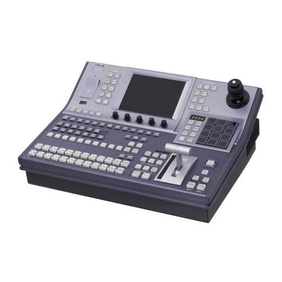
Names and Functions of Parts Chapter Control Panel Types In this system, you can use any one of the three control panels shown on the following page. This manual refers to these control panels by the names shown in parentheses ( ) in the figure on that page. - Page 10 SHIFT HOLD NEXT TRANSITION COLOR DSK1 COLOR BKGD TRANSITION TYPE COLOR AUTO AUTO BKGD TRANS TRANS FRAMES DSK1 MKS-2010 Control Panel (1 M/E panel) EFFECT MENU BVLD TRAIL/ LIGHT EDGE SHDW BORD SOFT CROP /WIPE SNAP SHOT STORE MCRO AUTO...
-
Page 11: Control Panel Configuration
Control Panel Configuration 1.5 M/E panel and 1.5 M/E wide panel The sole difference between these control panels is the number of cross-point buttons per row. Most of the illustrations in this manual show the configuration of the 1.5 M/E panel. Power Indicators, “Memory Stick”... -
Page 12: M/E Cross-Point Control Block
1 M/E panel See the pages in parentheses ( ) for the functions of the illustrated parts. Power Indicators, “Memory Stick” Slot, USB Connector (page 23) POWER EDIT DEVICE/UTILITY DEV1 AUX DELEGATION AUX1 KEY1 BLACK BLACK BLACK M/E Cross-Point Control Block (page 12) AUX Bus Control Block (page 15) Utility Control Block (page 22) M/E Cross-Point Control Block... - Page 13 Background A row BLACK BLACK Background B row a Cross-point button rows Select background video by pressing the corresponding button. The buttons in the background A row select the background video which is output before the start of a transition (A bus video). Pressing a button selects the signal assigned to that button (input signals to the IN1 to IN16 connectors of the processor, or signals which the...
-
Page 14: Pgm/Pst Cross-Point Control Block
Note This button does not light and does not function when you are using the rightmost buttons in the cross-point button rows (the 12th or 20th buttons) as [SHIFT] button. PGM/PST Cross-Point Control Block Use the PGM/PST (program/preset) cross-point control block to select the video signals to be used as the background in program video (final output video). -
Page 15: Aux Bus Control Block
AUX Bus Control Block Use this block to select key signals and to select the signals to which a variety of functions are applied. 1 AUX delegation buttons AUX DELEGATION AUX1 AUX2 AUX3 KEY1 KEY2 DSK1 DSK2 BLACK a AUX delegation buttons By pressing one of the following buttons, lighting it, you select the bus to which the cross-point button row 6 is assigned. -
Page 16: M/E Transition Control Block
than key buses. For key buses, you can select any of the following three options as the operating mode when a snapshot is recalled with this button on. • Cross-point hold (retain the current cross-point selection state) • Key disable (retain the current key settings) •... -
Page 17: Pgm/Pst Transition Control Block
a Transition execution section (This figure shows the transition execution section on the 1.5 M/E and 1.5 M/E wide panels.) Transition indicator Fader lever AUTO TRANS FRAMES Transition rate display section Fader lever: Move the lever up and down to execute the transition. -
Page 18: M/E Key Transition Control Block
1 Transition execution section COLOR WIPE TRANSITION TYPE AUTO TRANS FRAMES 2 Transition type selection buttons a Transition execution section This works in the same way as the transition execution section in the M/E transition control block (see page 16). b Transition type selection buttons To select the type of transition, press one of the following buttons, turning it on. -
Page 19: Flexi Pad Control Block
See “Setting Transition Rates” (page 69) for more information about how to specify transition rates. b DSK PVW (downstream key preview) button You can press this button, turning it on, to temporarily switch M/E PVW output (1 M/E panel) or PST output (1.5 M/E panel) to DSK PVW output. -
Page 20: Effect/Wipe Control Block
b Region selection buttons Used in modes other than macro mode. Select the target function block of the operation. The button which is on lights in amber. M/E button: Selects the M/E region. PP/ALL (PGM/PST/all) button (on 1.5 M/E panel): In snapshot mode, selects all regions. - Page 21 EFFECT BVLD LIGHT EDGE BORD SOFT a Delegation selection buttons Select operation targets. M/E 1CH (M/E1 channel), M/E 2CH (M/E2 channel) buttons: Select M/E1 channel or M/E2 channel or both as the operation target(s). P/P (PGM/PST) button (on 1.5 M/E panels only): Selects PGM/PST as the operation target.
-
Page 22: Utility Control Block
BORD (border): When this button is on, you can add borders. The button lights in amber when no border parameters have been assigned to the knobs in the menu control block, and lights in green when they have been assigned. SOFT (soft edges): When this button is on, you can add soft edges. -
Page 23: Macro Control Block
Macro Control Block MACRO POST ATTCH MCRO MCRO ENBL 3 ATTCH ENBL button 2 POST MCRO button 1 PRE MCRO button a PRE MCRO button Use this button to set a macro attachment in pre macro mode. When you make settings in macro only mode, this button is used together with the Macro Only Set button, assigned to one of the buttons in the utility control block. -
Page 24: Memory Sticks
Installing a second power supply requires the optional HK- PSU11 Power Supply Unit. b “Memory Stick” status indicator Lights in red during access to a “Memory Stick.” c “Memory Stick” slot Insert “Memory Sticks.” See ““Memory Sticks”” (page 24) for more information about the usable “Memory Sticks”... -
Page 25: Chapter 3 Using Menus
Using Menus Accessing Menus Accessing Menus From the Top Menu Chapter The menus of this switcher enable you to make system settings and settings related to effects. To access menus, you can use any of the following three methods. • Access from the top menu (see next section) •... -
Page 26: Accessing Menus By Double Clicking
Accessing Menus by Double Clicking Accessing Menus Note The menu illustrations in this manual may differ in appearance from the menus actually shown in the menu display of the control panel. Press the [TOP/SHUTDOWN] button in the menu control block. The top menu appears. - Page 27 Menus accessed by double clicking Button Button Menu location M/E cross-point Misc >Color Bkgd COLOR BKGD control block Frame Memory >Recall FM1 VIDEO Frame Memory >Recall FM1 KEY Frame Memory >Recall FM2 VIDEO Frame Memory >Recall FM2 KEY Frame Memory >Recall FM3 VIDEO Frame Memory >Recall FM3 KEY...
-
Page 28: Accessing Menus By Single Clicking
Accessing Menus by Single Clicking Accessing Menus Menus accessed by double clicking Button Button Menu location M/E transition KEY1 Key >M/E Key1 >Main control block KEY2 Key >M/E Key2 >Main Effect/Wipe >M/E Effect >Main Page 63 PST COLOR MIX Misc >Transition PGM/PST WIPE Effect/Wipe >P/P Wipe >Main... -
Page 29: Interpreting Menu Screens
Interpreting Menu Screens Basic Screen There are two types of menu screen. • Basic screen (see next section) • Popup windows - General popup windows (see page 32) - General popup windows (scrolling type) (see page 33) - Numeric keypad window/timecode window (see page 33) - Hexadecimal keypad window (see page 35) - Keyboard window (see page 36) - Page number input window (see page 38) - Page 30 For details about page numbers, refer to “Menu Tree” in the Appendix (separate document). b Back button Returns to the most recently displayed menu. You can go back up to maximum of 50 menus. This button is disabled when the display history has been erased and when you have backed up through the entire display history.
- Page 31 Status area Button area Interpreting buttons The following figure shows the information displayed on function buttons. Function name Lights in light blue when parameters are assigned to knobs. Status display The following table shows how to interpret other buttons. Name Display State Parameter...
-
Page 32: Popup Windows
Popup Windows General popup windows Interpreting Menu Screens Icons displayed on buttons The following table shows the icons which are displayed on buttons, and the functions which they represent. The functions are executed when a button with the corresponding icon is pressed. Name Display Function... - Page 33 General popup windows (scrolling type) Numeric keypad window/timecode window b Close button Closes the popup window. 1 Function button area 4 Page Up, Page Down buttons 3 Window Hold button a Function button area Displays functions and menus for selection. The popup window closes when you press a button in this area.
- Page 34 Interpreting Menu Screens 1 Input value display 2 Minimum to maximum display 7 Enter button 6 Numeric input buttons a Input value display Shows the value entered in the numeric keypad window or the timecode window. In the timecode window, values are shown in the format HH:MM:SS:FF (Hours:Minutes:Seconds:Frames).
- Page 35 c Item display Displays the name of the parameter being set in the numeric keypad window or timecode window. d – (minus) button Changes the sign of the input value. Each press toggles between plus (+) and minus (–). Not supported in the timecode window. e Close button Closes the numeric keypad window or the timecode window.
- Page 36 a Input value display Shows the value entered in the hexadecimal keypad window. b Item display Displays the name of the parameter being set in the hexadecimal keypad window. c Minimum to maximum display Displays the minimum and maximum values that can be set for the parameter. d Close button Closes the hexadecimal keypad window.
- Page 37 1 Item display 2 Input string display 3 Left button 4 Right button 5 Close button qa Enter button q; Del button 9 Clear button 8 BS button 7 Shift button 6 Caps Lock button a Item display Shows the name of the parameter being set in the keyboard window. b Input string display Shows the character string being input in the keyboard window.
-
Page 38: Clear Button
i Clear button Clears all of the characters in the input string. j Del (delete) button Clears the character immediately after the cursor in the input string. k Enter button Sets the input string as a parameter value. Closes the keyboard window if the value was valid. If the value was not valid, the window stays open and the color of the input value display changes to red. -
Page 39: Basic Menu Operations
Basic Menu Operations Selecting Menus Selecting by navigating the menu tree There are three ways to select menus. • Navigate the menu tree (see next section) • Enter a page number (see page 40) • Select from the display history (see page 40) You can display a desired menu by navigating to it through the menu tree from the currently displayed menu. -
Page 40: Selecting Functions
Selecting menus by entering page numbers Selecting menus from the display history Selecting Functions Setting Parameters Basic Menu Operations Select [Color Bkgd]. The popup window closes and the display changes to the Color Bkgd menu. You can display a desired menu by entering its page number. For more information about page numbers, refer to “Menu Tree”... - Page 41 Parameter group name Knob 1 Knob 2 Parameter values can be set with either of the following methods. • Rotate the knobs (1 to 5) corresponding to the parameters. • Press the parameter button corresponding to a parameter, and enter a numeric value in the numeric keypad window.
-
Page 42: Exiting The Menu System
Exiting the Menu System Exiting the Menu System To exit the menu system, proceed as follows. Note Always exit the menu system before powering the control panel off. In the menu control block, press the [TOP/SHUTDOWN] button. The top menu appears. Press [Shutdown]. -
Page 43: Chapter 4 Basics Of Video Switching
Basics of Video Switching Chapter This chapter begins by explaining how to switch background signals on the M/ E bank (how to perform transitions). Then it explains basic background video switching on the PGM/PST bank when a 1.5 M/E panel or 1.5 M/E wide panel is used. -
Page 44: Basic Operations (1): Video Switching On
Basic Operations (1): Video Switching on the M/E Bank Transition start 1.5 M/E panel Basic Operations (1): Video Switching on the M/E Bank Let’s begin by using the M/E bank to select video signals showing a landscape and a lion as background video, and to switch between them with an effect. As the effect, we will use effect number 0024 (circular wipe). - Page 45 In the background A row of the M/E cross-point control block, select the A bus video. For this example, press the 2nd button from the left to select the landscape video signal. The landscape video appears on the video monitor connected to the processor’s program output (final output) connector.
- Page 46 Basic Operations (1): Video Switching on the M/E Bank Now, notice again how the buttons in the background A and B rows are lit. With the transition complete, the 3rd button from the left in the A row is lit in red, and the 2nd button from the left in the B row is lit in amber.
-
Page 47: Basic Operations (2): Video Switching On The Pgm/Pst Bank - For 1.5 M/E Systems
Basic Operations (2): Video Switching on the PGM/ PST Bank — For 1.5 M/E Systems Transition start If you are using a 1.5 M/E panel or a 1.5 M/E wide panel, you can create the program video (final output video) on the PGM/PST bank. You can select background video and execute transitions with the same operations as the ones used on the M/E bank. - Page 48 Basic Operations (2): Video Switching on the PGM/PST Bank — For 1.5 M/E Systems In the PGM row of the PGM/PST cross-point control block, press the [M/ E] button at the right edge. The [M/E] button lights in red, and the output video of the M/E bank (the lion) is selected as the PGM bus video.
-
Page 49: Chapter 5 Basic Operations
Basic Operations Selecting Video Flow of Operations : Always done Select video (page 49) : Done as required : Done at this stage Select the transition type (page 53) Select an effect (page 56) Select the operating channels (page 61) When mix or preset color mix Change the position and size of the effect pattern (page 63) -
Page 50: Selecting Video In The M/E Cross-Point Control Block
Selecting Video in the M/E Cross-Point Control Block 1.5 M/E panel Selecting Video To execute a background video transition, you need to prepare by selecting the background video before and after the transition on the M/E cross-point control block. When using the 1.5 M/E panel or 1.5 M/E wide panel Program video (final output video) is created with the background video selected on the PGM/PST cross-point control block. -
Page 51: Selecting Video In The Pgm/Pst Cross-Point Control Block
Selecting Video in the PGM/PST Cross-Point Control Block Selecting Video in the AUX Bus Control Block When the button pressed to select background video is lit in red, the video is displayed on the video monitor connected to the processor's program (final video) output connector. - Page 52 1.5 M/E panel Selecting Video Press one of the AUX delegation buttons to select the bus to which the cross-point button row is assigned. Press one of the buttons in cross-point button row to select the desired signal. When a signal on the selected bus is being output to program video, the corresponding button lights in red (high tally).
-
Page 53: Selecting Transition Types
Selecting Transition Types Flow of Operations : Always done : Done as required Select video (page 49) : Done at this stage Select the transition type (page 53) Select an effect (page 56) Select the operating channels (page 61) When mix or preset color mix Change the position and size of the effect pattern (page 63) is selected... -
Page 54: Selecting The Transition Type And The Next Transition
Selecting the Transition Type and the Next Transition Transition type selection buttons (for PGM/PST bank) 1.5 M/E panel To select the transition type Selecting Transition Types Next transition selection buttons Transition type selection buttons Transition type selection buttons (for M/E bank) Press one of the transition type selection buttons in the M/E transition control block or the PGM/PST transition control block, lighting the button. - Page 55 To select the next transition Select the target of the setting. • Press [M/E Pst Col] to select a color matte for the M/E bank. • Press [P/P Pst Col] to select a color matte for the PGM/PST bank (1.5M/ E panel only).
-
Page 56: Selecting Effects
Selecting Effects Flow of Operations : Always done : Done as required : Done at this stage Select an effect (page 56) Select the operating channels (page 61) When mix or preset color mix Change the position and size of the effect pattern (page 63) is selected Modify the video border (page 66) Prepare the transition (page 69) -
Page 57: Selecting Effects With The Flexi Pad Control Block
Selecting Effects With the Flexi Pad Control Block 1.5 M/E panel Press the [EFF/WIPE] button in the Flexi Pad control block. EFF/ WIPE SNAP SHOT STORE MCRO ENTR BANK TRANS RATE Select the setting target with the delegation buttons. • To set the M/E bank, press the [M/E] button. •... -
Page 58: Selecting Effects From Menus
Selecting Effects From Menus Selecting Effects Refer to “Effect Pattern List” in the Appendix (separate document) for more information about effect patterns. The entered effect pattern number appears in the numeric display. Note Effects numbered 1001 and higher cannot be used when: •... - Page 59 To scroll the popup window Do one of the following. • Use the scroll bar on the right. • Rotate knob 1. Each rotation scrolls 1 line up or down. • Press [Page Down] or [Page Up]. Each press scrolls 3 lines up or down. To select the desired pattern from a group of patterns, press [Group Select].
-
Page 60: Effect Types
Effect Types Selecting Effects Press the button for the desired pattern. The effect pattern is confirmed, the popup window closes, and you are returned to the Main menu. About effect pattern numbers The effects available on this system can be selected with 4-digit effect pattern numbers. -
Page 61: Selecting Channels
Selecting Channels To select channels with the Effect/Wipe control block To select channels from menus Setting the parameters of 2-channel effects Note When you add a shadow or trail to an effect applied to a key and then execute the transition, the shadow or trail disappears instantly as soon as the transition ends. - Page 62 Note Among the parameters listed above, the following parameters are exceptions. For the indicated effects, they are set for both channels. • Position of the Ripple (2ch) effect • Crop of the Page Roll (2ch) effect • Crop of the Page Turn (2ch) effect Parameters common to both channels Parameters other than the above are set for both channel 1 and channel 2, even if only one of the channels has been selected with the [M/E 1CH] and [M/E...
-
Page 63: Changing The Position And Size Of Effect Patterns
Changing the Position and Size of Effect Patterns Flow of Operations : Always done : Done as required Select video (page 49) : Done at this stage Select the transition type (page 53) Select an effect (page 56) Select the operating channels (page 61) When mix or preset color mix Change the position and size of the effect pattern (page 63) -
Page 64: Changing Pattern Position And Size With The Joystick
Changing Pattern Position and Size With the Joystick 1.5 M/E panel Changing Pattern Size and Position From Menus Changing the Position and Size of Effect Patterns CTR button Press the [POS] button in the Effect/Wipe control block, lighting it. The joystick is assigned to the positioner (which changes effect pattern position and size). -
Page 65: For A 2-Channel Effect, Select The Channel Or Channels For Which You Want To
Press [Position], turning it on. For a 2-channel effect, select the channel or channels for which you want to make settings. (See “To select channels from menus” (page 61).) (You can set the parameters for the individual channels.) Set the following parameters with the knobs. Knob Description 1 (H Position) -
Page 66: Modifying Video Borders
Modifying Video Borders Flow of Operations : Always done : Done as required : Done at this stage Select an effect (page 56) Select the operating channels (page 61) When mix or preset color mix Change the position and size of the effect pattern (page 63) is selected Modify the video border (page 66) Prepare the transition (page 69) -
Page 67: Adding Borders To Video
Adding Borders to Video 1.5 M/E panel To set border colors SOFT button 1 M/E panel Press the [BORD] button in the Effect/Wipe control block, lighting it. Or, turn [Border] on in the Effect/Wipe >M/E Effect >Main menu (see page 58). -
Page 68: Softening Video Edges (Soft Edge/Soft Border)
Softening Video Edges (Soft Edge/Soft Border) Modifying Video Borders The popup window closes. Set the following parameters with the knobs. Knob Description 1 (Lum) Luminance 2 (Sat) Saturation 3 (Hue) Press the [SOFT] button in the Effect/Wipe control block, lighting it. Or, turn [Soft] on in the Effect/Wipe >M/E Effect >Main menu. -
Page 69: Preparing Transitions
Preparing Transitions Flow of Operations : Always done : Done as required Select video (page 49) : Done at this stage Select the transition type (page 53) Select an effect (page 56) Select the operating channels (page 61) When mix or preset color mix Change the position and size of the effect pattern (page 63) is selected... - Page 70 To set transition rates with the Flexi Pad control block Transition rate display 1.5 M/E panel To set transition rates from menus Preparing Transitions In the Flexi Pad control block, press the [TRANS RATE] mode selection button, lighting it. The Flexi Pad control block enters transition rate input mode. Select the target of the setting with the delegation selection buttons.
-
Page 71: Selecting Effect Directions
Selecting Effect Directions Select the target of the setting. • Press [M/E] to set for the M/E bank. • Press [P/P] to set for the PGM/PST bank (when using the 1.5M/E panel). The numeric keypad window appears. Enter a number of frames in the range 0 to 999 and press [Enter]. This confirms the input. -
Page 72: From The Top Menu, Select Effect/Wipe >M/E Effect >Main
To select effect directions with the Effect/Wipe control block N/R button 1.5 M/E panel To select effect directions from menus Preparing Transitions REV button N/R button 1 M/E panel To select the normal direction: Turn both the [REV] button and [N/R] button off, so that they are not lit. -
Page 73: Executing Transitions
Executing Transitions Flow of Operations : Always done : Done as required Select video (page 49) : Done at this stage Select the transition type (page 53) Select an effect (page 56) Select the operating channels (page 61) When mix or preset color mix Change the position and size of the effect pattern (page 63) is selected... - Page 74 AUTO TRANS button 1.5 M/E panel To switch the video instantly ([CUT] button) To execute a transition at a specified transition rate ([AUTO TRANS] button) To execute a transition with the fader lever About fader lever non-sync Executing Transitions Fader lever AUTO TRANS button CUT button Fader lever...
- Page 75 • Moving the lever toward the side where LEDs are lit does not execute a transition. However, the non-sync state is released when the lever reaches the edge of its range, enabling you to execute a transition with the next operation. •...
-
Page 76: Composing Video With Keys
Composing Video With Keys Flow of Operations : Always done : Done as required : Done at this stage Select an effect (page 56) Select the operating channels (page 61) When mix or preset color mix Change the position and size of the effect pattern (page 63) is selected Modify the video border (page 66) Prepare the transition (page 69) -
Page 77: M/E Keys And Downstream Keys
M/E Keys and Downstream Keys Inserting Text With a Luminance Key or Linear Key To select luminance or linear key and set the key parameters Two keys each are available on the M/E bank and the PGM/PST bank. The M/ E bank keys are called key 1 and key 2, and the PGM/PST bank keys are called downstream key 1 and downstream key 2. - Page 78 To select a key source Composing Video With Keys To select a luminance key, press [Luminance]. To select a linear key, press [Linear]. The popup window closes. Set the following parameters with the knobs. Knob Description 1 (Clip) Reference level for key signal generation +109.59 to –7.31 2 (Gain) Gain of key 3 (Density)
- Page 79 KEY1 button SRC BUS button (lit) KEY button Cross-point button row 1.5 M/E panel To select a key fill KEY1 button SRC BUS button (lit) Cross-point button row In the Key >M/E Key1 >Main menu (see page 77), press [Key Fill]. A popup window appears.
- Page 80 KEY1 button SRC BUS button (not lit) Cross-point button row 1.5 M/E panel To insert and delete keys Composing Video With Keys KEY1 button SRC BUS button (not lit) Cross-point button row To adjust the key fill color When you select “Matte” as the key fill, you can obtain the desired color with the following procedure.
-
Page 81: Composing Video With Chroma Keys
Composing Video With Chroma Keys To select chroma key To select a chroma key source To select a chroma key fill To adjust auto chroma key For more information about key transitions, see “To select the next transition” (page 55), “Preparing Transitions” (page 69), and “Inserting and Deleting Keys Only”... -
Page 82: Composing Video With Pattern Keys
To adjust chroma key video Composing Video With Pattern Keys To select pattern key and set the key parameters Composing Video With Keys Knob Description 1 (H Position) Move the sample mark horizontally. 2 (V Position) Move the sample mark vertically. 3 (Size) Adjust the size of the sample mark. -
Page 83: Adding Borders To Keys
About the pattern key source To select the key fill for a pattern key To transform the pattern used in a pattern key Adding Borders to Keys In the pattern key, a wipe pattern is selected automatically as the key source. No user operation is required. -
Page 84: Masking Part Of A Key
Masking Part of a Key Composing Video With Keys The popup window closes. Set the following parameters, depending on what you selected in step 2. When Border or Outline was selected (with the separate edge function (see page 105) being off): Knob Description 1 (Width) -
Page 85: Moving A Key Over Or Under
Moving a Key Over or Under To check whether a key is over or under To move a key over or under from menus Key mask Masked area (box) In the Key >M/E Key1 >Main menu (see page 77), press [Mask]. A popup window appears. -
Page 86: Inserting And Deleting Keys Only
To move keys over and under in a transition Inserting and Deleting Keys Only To insert or delete a key by mixing (independent key transition) 1.5 M/E panel To insert or delete keys instantly Composing Video With Keys Press one of the following. Over: The target key is moved to over. - Page 87 To insert or delete M/E keys instantly If you are using the 1.5M/E panel, press the [KEY1 ON] button or the [KEY2 ON] button in the M/E key transition control block. If you are using the 1 M/E panel, press the [KEY1 ON] button or the [KEY2 ON] button in the M/E transition control block.
-
Page 88: Using Internally Generated Signals
Using Internally Generated Signals Flow of Operations : Always done : Done as required : Done at this stage Select an effect (page 56) Select the operating channels (page 61) When mix or preset color mix Change the position and size of the effect pattern (page 63) is selected Modify the video border (page 66) Prepare the transition (page 69) - Page 89 To set color 1 To compose a pattern of two colors (color mix) Color background (single-color) From the top menu, select Misc >Color Bkgd. The Color Bkgd menu appears. The [Color1] button shows the current color. Press [Color1]. A popup window appears. Press the button for the color that is closest to the desired color.
- Page 90 To transform color mix patterns Using Internally Generated Signals Compose the pattern by using the knobs to set the following parameters. Knob Description 1 (Size) Size of pattern 2 (Soft) Softness of edges 3 (Pattern) Pattern number a) Same as patterns in the standard group. Press [Color1].
- Page 91 To change the aspect ratio of a pattern From the top menu, select Misc >Color Bkgd, then press [Aspect], turning it on. Set the following parameter with knob 1. Knob Description 1 (Aspect) Aspect ratio of pattern a) Minus values make the pattern taller, and plus values make the pattern longer. To rotate an effect pattern From the top menu, select Misc >Color Bkgd, then press [Rotation].
- Page 92 To exchange color 1 and color 2 Using Internally Generated Signals H Modulation gives horizontal modulation, and V Modulation gives vertical modulation. Adjust the following parameters with the knobs. Knob Description 1 (Amplitude) Amplitude of modulation wave 2 (Frequency) Frequency of modulation wave 3 (Speed) Speed of modulation a) In H Modulation, maximum speed is at –100.00 in the left direction and +100.00 in the right...
-
Page 93: Fading The Video To Black
Fading the Video to Black Flow of Operations : Always done : Done as required Select video (page 49) : Done at this stage Select the transition type (page 53) Select an effect (page 56) Select the operating channels (page 61) When mix or preset color mix Change the position and size of the effect pattern (page 63) - Page 94 1.5 M/E panel To fade out the video with fade to black Fading the Video to Black From the top menu, select Misc >Transition. The Transition menu appears. After pressing [FTB], enter a transition rate in the numeric keypad window. (See “Setting Transition Rates”...
-
Page 95: Chapter 6 Advanced Operations
Advanced Operations Advanced Effect Operations The procedures in this section mainly show how to operate with M/E effects (effects used on the M/E bank). The same procedures can also be used with PGM/PST wipes (wipes used on the PGM/PST bank). Transforming Effect Patterns Note that some effect patterns cannot be transformed. - Page 96 Set the following as required. Angle: Slant the pattern at a specified angle. Speed: Rotate the pattern at a specified speed. Magnitude: Rotate the pattern to a specified angle during the transition. Set the following parameters according to the selection in step 2.
-
Page 97: Cropping Effects
Knob Description 3 (Invert Type) Replication layout 1: All patterns point in same direction 2: Even numbered rows move in horizontal direction 3: Even numbered columns and rows are inverted 4: Even numbered columns and rows are inverted, and even numbered rows move in horizontal direction For an M/E effect, do the following to invert the direction of every other pattern. -
Page 98: Adding Beveled Edges To Video
To set a relationship between transition progress and cropping Carry out the procedure in the previous section “To turn th crop function on” (see page 97). In the Crop menu, press [Crop Trans]. A popup window appears. Select one of the following, as required. Cut: Cut mode. - Page 99 Select the operating channels. (See “Selecting Channels” (page 61).) Set the following parameters with the knobs. Light mode: Knob Description Setting values 1 (Inten 1) Luminance of 0.00 to 200.00 edges on side close to light source 2 (Inten 2) Luminance of 0.00 to 200.00 edges on side away from light source...
-
Page 100: Adding Lighting
Adding Lighting This operation can only be carried out on M/E effects. It is not supported for some patterns. For more information, refer to “Effect Pattern Transformations and Modifications” in the Appendix (separate document). Lighting types There are three types of lighting. The type of lighting is fixed in advance for each effect number. - Page 101 Trail To add afterimages Notes • Trails are added to both channels of 2-channel effects. They cannot be added to nor adjusted for individual channels. • When Trail is enabled, Shadow (see page 102) is disabled. Press the [TRAIL/SHDW] button in the Effect/Wipe control block, turning it on.
-
Page 102: Adding Shadows Around Effects
Set the following parameters with the knobs. Knob Description 1 (Trail Dust) Amount of the afterimage disappearing as stardust 2 (Dust Soft) Timing with which stardust disappears 3 (Dust Size) Size of stardust a) 0.00 is no afterimages. 100.00 is no transformation of afterimages into stardust. -
Page 103: Using Pattern Specific Transformations
Set the pattern used to mix the 2 colors, and specify color 1 and color 2. See “To compose a pattern of two colors (color mix)” (page 89) and “To transform color mix patterns” (page 90) for information on how to set the parameters. -
Page 104: Advanced Key Operations
Note Pressing a button which is lit in orange or yellow will overwrite the current contents of the register. When the save is complete, the button that you pressed lights in yellow and the number on the button changes from a register number to an effect pattern figure. The pattern number appears in the numeric display. -
Page 105: Adjusting Key Borders
To invert key signals You can invert the black/white of key signals. This allows you to use a key source as black characters against a white background and white characters against a black background. To turn the key inversion function on, in the Key >M/E Key1 >Key Source menu, press [Key Invert], turning it on. -
Page 106: Adjusting Chroma Keys
4H Mode: Set the maximum width to 4 (4 lines). Key fill and key source drop down by 4 lines. 8H Mode: Set the maximum width to 8 (8 lines). Key fill and key source drop down by 8 lines. Adjusting Chroma Keys Proceed as follows to make fine adjustments to the chroma key image obtained with auto chroma key (see page 81). - Page 107 To make adjustments with color cancel If the foreground image includes shades of the background color, turn this function on to remove the color from the foreground image. In the Key >M/E Key1 >Chroma Key menu, turn [Key Active] off, and turn [Color Cancel] on. Set the following parameters with the knobs.
- Page 108 Crop Range of colors remaining as foreground Range of colors creating the key signal (to be replaced by background signal) a) The Crop and Angle values do not change even if you use the auto chroma key function. To adjust the window, the Clip, Gain, Hue must be adjusted to appropriate values.
-
Page 109: Transforming The Pattern Of A Pattern Key
Transforming the Pattern of a Pattern Key From the top menu, select Key >M/E Key1 >Pattern Key. The Pattern Key menu appears. Press one of the following buttons, depending on what you want to adjust. For details about operation, see the sections on effect transformations (on the pages indicated in parentheses). -
Page 110: Using The Show Key Function
When Pattern was selected: Knob Description 1 (Size) Size of pattern 2 (Soft) Softness of edges 3 (Pattern) Pattern number a) Same as patterns in the standard group. To invert a mask signal In the Key >M/E Key1 >Mask menu, press [Mask Invert], turning it on. -
Page 111: Color Correction
Color Correction Color correction (CCR) enables input video color correction (black balance/white balance adjustment, gamma correction, knee correction, etc.). Note The following optional boards are required to use the color correction function. • MKS-2420M Color Corrector Board • MKS-2440 Frame Memory Board Set The MKS-2420M is mounted on the MKS-2440. -
Page 112: Input Video Processing
To enable a color corrector The following example shows how to enable color corrector 1 (CCR1). You can proceed in the same way to enable CCR2. From the top menu, select CCR >CCR1. Press a menu button other than [Mask1] or [Mask2] to display the menu. -
Page 113: Primary Color Correction
Knob Description 1 (Video Gain) Overall video signal gain 2 (Y Gain) Y signal gain 3 (C Gain) C signal gain 4 (Hue Delay) Hue delay 5 (Black Level) Black level To return input video processing parameters to their default settings Press [Unity]. -
Page 114: Secondary Color Correction
Knob Description 4 (All) Knee correction of R, G, and B signals (adjusted at once) To return primary color correction parameters to their default settings Press [Unity]. To mask part of the primary color correction Note The mask function is common to the following color correction functions. -
Page 115: Rgb Clip
Press [Secondary], turning it on. Press the button for the color to adjust ([Blue], [Cyan], [Green], [Yellow], [Red], or [Magenta]), then adjust the following parameters. Knob Description 1 (Lum) Luminance 2 (Sat) Saturation 3 (Hue Hue delay Delay) To return secondary color correction parameters to their default settings Press [Unity]. - Page 116 Tint: Add a specified color to the original video signal. Color Modify: Adjust the original video signal. Y Modify: Adjust the output levels of the input luminance signal. If you selected [Tint] or [Color Modify], proceed to step 5. If you selected [Y Modify], adjust the following parameters.
-
Page 117: Spot Color Adjustment
Spot Color Adjustment You can change the color in a specified region to another color, without affecting other regions. You can also adjust the following in the regions outside the spot color adjustment region. • Video signal overall gain • Y signal gain •... -
Page 118: Output Video Processing
To return [Outer Proc] parameters to their default settings Press [Outer Unity]. Output Video Processing You can adjust the following for YUV signals. • Overall gain of video signal • Y signal gain • Y signal offset • C signal gain •... -
Page 119: Frame Memory
Knob Description 4 (V Nega Clip) Negative clip adjustment for V signal To return YUV clip parameters to their default settings Press [Unity]. Setting values Frame Memory –113.39 to +113.39 Frame memory is a function whereby a frame of input video can be frozen and written to memory, for further use as material for editing. -
Page 120: Preparations
Preparations Assigning frame memory output to cross- point buttons Frame memory images (freeze images, etc.) can be assigned to either the video or key channels of frame memory 1 to 3. The following three types of output destinations are available (six channels). •... - Page 121 Note In the following signal formats, a field freeze is not possible. 1080PsF/23.976, 1080PsF/24, 1080PsF/25, 1080PsF/ 29.97, 720P/59.94 This freezes the input image. In this state, no freeze image has yet been saved. You can repeat this operation any number of times, until the desired freeze image is obtained.
-
Page 122: Recalling Freeze Images Saved In Frame Memory
For example, if you select [FM2 V/K], the thumbnails in the Freeze menu (see page 120) change to [FM2V] and [FM2K]. To delete a freeze image Press [Frz Off]. The thumbnails in the Freeze menu ([FM1V] and [FM1K] in the figure on page 120) change to black. - Page 123 • Turn the knob. Knob Description Setting values 1 (No) File number 1 to number of saved image files For Pair files, the video and key files are selected together. It is not possible to select either individually. Press [Rename]. A popup window appears.
-
Page 124: Snapshots
Snapshots What are Snapshots? The term “snapshot” refers to a function whereby the various settings required to apply a particular effect to an image are saved in memory as a set of data, for recall as required, to recover the original state. Snapshot operations use the Flexi Pad control block. -
Page 125: Saving Snapshots
Saving Snapshots EFF/ WIPE SNAP SHOT STORE MCRO DISS BANK TRANS RATE Set up the state that you want to save as a snapshot. Press the [SNAPSHOT] button, turning it on. The Flexi Pad control block enters snapshot operation mode. Press and light the region selection button for the region which you want to save. -
Page 126: Recalling Snapshots
Recalling Snapshots EFF/ WIPE SNAP SHOT STORE MCRO DISS BANK TRANS RATE Press the [SNAPSHOT] button, turning it on. The button lights in amber, and the Flexi Pad control block enter snapshot operation mode. Also, the numeric display shows the number of the bank selected last time, and the number of the register most recently recalled for the region. -
Page 127: Macros
Macros What Are Macros? The term “macro” refers to the function whereby a sequence of signal selections and other operations on the control panel is saved as data in memory, so that it can be recalled as required to automatically execute the same sequence of operations. - Page 128 The display on the memory recall buttons changes to the state shown in the above figure. You can now select the save destination bank. For details of the correspondence between banks and registers, see page 125. Press a memory recall button to select a bank. The most significant digit in the numeric display shows the number of the selected bank.
-
Page 129: Recalling A Macro Register And Executing A Macro
When the [AUTO INS] button lights in orange (this mode is off), it is necessary to press the [INS] button for each operation to register the event. Note When you start macro creation or editing with the macro execution mode set to “Normal” (see page 175), the auto insert mode is automatically on. - Page 130 Executing a macro in normal execution mode EFF/ WIPE SNAP SHOT STORE MCRO BANK TRANS RATE In the Flexi Pad control block, press the [MCRO] button, turning it on. This assigns the Flexi Pad control block to macro operation. Press the [BANK SEL] button, turning it on. The display on the memory recall buttons changes to the state shown in the above figure.
-
Page 131: Editing A Macro
The number of events executed, as shown in the memory recall button, is incremented by one. Repeat step 2, executing the macro event by event. When all events in the macro have been executed, the [TAKE] button goes off. Editing a Macro After carrying out macro editing, be sure to carry out a save operation (see page 132). -
Page 132: Saving A Macro
However, the macro assigned to the button is not executed. Saving a Macro Press the [STORE] button or memory recall button [STOR XX] (where XX is the register number) to save the edited macro in a register. To return to the state before editing, without saving the macro editing results Press the memory recall button [EXIT] to recall the same register again. - Page 133 Recall the macro register you want to assign to the button. For details of the method of operation, see “Executing a macro in normal execution mode” (page 130). To set in macro only mode, press the button to which [Mcro Only Set] is assigned, turning it on. To set in pre or post macro mode, proceed to step 3.
-
Page 134: Safe Title
• During macro execution, if you switch the Flexi Pad control block to macro edit mode, the macro being executed stops. • During macro editing, pressing a button for which a macro attachment is set does not execute the macro. To disable macro attachment settings Press the [ATTCH ENBL] button, turning it off. -
Page 135: Copying
Copying Copy Operation Targets You can copy setting states between the following four keyers. Setup data and key memory data is not copied. • M/E key 1 • M/E key 2 • Downstream key 1 (DSK1) • Downstream key 2 (DSK2) Using Buttons to Copy Key Settings You can easily copy keyer settings by using the AUX delegation buttons ([KEY1], [KEY2], [DSK1], and... - Page 136 Copying...
-
Page 137: Chapter 7 File Operations
File Operations Overview You can save register data, including setup data and snapshot data, and load the saved data whenever it is needed. Data can be saved to either the built-in hard disk or a “Memory Stick” (see page 24) as a file. The system distinguishes between several different kinds of data. -
Page 138: Loading All Data At Once
“1 SYSTEM” is specified as the target directory. (No other directory can be selected.) Press the button for the desired media type (Hard Disk, or Memory Stick). The color of the pressed button is inverted. Press [OK]. The popup window closes. In the File >All menu, press [All Save]. -
Page 139: Batch Operating On Data Files Of Selected Categories
Batch Operating on Data Files of Selected Categories Use the File >All (Selected) menu to operate on data in selected categories (except frame memory image data). Saving the Data of Selected Categories You can save the data for one or more categories in a single operation. -
Page 140: Deleting The Data Of Selected Categories
If you pressed [Yes], the load begins and a window opens to show its progress. Note that all existing data in the load destination registers are deleted before the load starts. To cancel a load after it has started Press [Cancel] in the progress window, and press [OK] in the message box which appears to inform you that the save has been cancelled. -
Page 141: Saving Data Files
The popup window closes. In the File >Load menu, press [Dest Register]. A list of destination registers appears in a popup window. Do one of the following to select the destination registers. • Press directly on the list in the popup window. •... -
Page 142: Deleting Data Files
Knob Description 2 (Number) Number of destination files When you are finished selecting files, press [OK]. The popup window closes. In the File >Save menu, press [Save]. A confirmation window appears asking if you want to execute the save. Press [Yes] in the confirmation window to execute the load, or [No] to cancel it. -
Page 143: Copying Data Files
Select the Frame Memory category, and as required the target media. For details about the procedure, see “Common Operations – Selecting the Frame Memory Category and the Target Media” (page 144). In the File >Rename menu, press [Target File]. A file list appears in a popup window. Do one of the following to select the file to rename. -
Page 144: Common Operations - Selecting The Frame
A confirmation window appears asking if you want to execute the copy. Press [Yes] in the confirmation window to execute the copy, or [No] to cancel it. If you pressed [Yes], the copy begins and a window opens to show its progress. To cancel a file copy after it has started Press [Cancel] in the progress window, and press [OK] in the message box which appears to inform you that... -
Page 145: Chapter 8 External Device
External Device Control From Editing Systems Overview You can control the MFS-2000 system from an external editing system by using 9-pin serial control signals and GPI signals. Refer to the documentation of your editing system for more information about operations on the editing system. Controllable Functions When using 9-pin serial control signals Following is a list of the functions which can be controlled... -
Page 146: Controlling External Devices
On the MFS-2000 system, you can control the following external devices from the RS-422A 9-pin serial interface of a Device Control Unit (DCU). • VTRs • Disk recorders (supporting Sony Disk 9-pin protocol) • Disk recorders (supporting the Video Disk Communications Protocol) • Extended VTRs (Abekas A53 protocol) •... -
Page 147: Checking Vtr, Disk Recorder, And Extended Vtr Information
Selecting devices to control Select devices to control by pressing the Device1 to Device6 selection buttons in the utility control block. You can select several devices. In this case, the device corresponding to the button which was pressed first becomes the reference device. The button of the reference device lights in green. - Page 148 Checking Device Status The following information is shown in the [Status] column. Status When the Video Disk display Communications Protocol is used XXXX Not communicating, or communicating but the device type cannot be read. Local Port is not open. Tape Out No file loaded.
-
Page 149: Disk Recorder/Extended Vtr File Operations
Disk Recorder/Extended VTR File Operations Internally, disk recorders and Extended VTRs manage recorded material in units of files. When using disk recorders and Extended VTRs for playback and recording, you need to perform the following file operations. Loading file lists: Before you can play a file from a disk recorder or Extended VTR, you need to display a list of the files stored on the device. - Page 150 Controlling External Devices The keyboard window appears. Enter a file name and press [Enter]. The maximum file name length is as follows. Disk recorder (Sony Disk 9-pin Protocol): 16 characters Setting values Disk recorder (Video Disk Communications Protocol): 8 characters...
-
Page 151: Simple Connection To Mks-8080/8082 Aux Bus Remote Panel
Simple Connection to MKS-8080/8082 AUX Bus Remote Panel You can connect the MKS-8080/8082 AUX Bus Remote Panel to enable remote control of the switcher’s AUX buses. To connect the MKS-8080/8082 to the control panel requires an HKSP-R80 Routing Switcher Controller Board or similar device constituting a primary station for an S- Bus data link, as well as various settings for connction. - Page 152 Simple Connection to MKS-8080/8082 AUX Bus Remote Panel...
-
Page 153: Basic Settings
System Settings Basic Settings Format Settings (Format Menu) Use the Format menu to set the signal format used in the switcher system, the input reference signal (HD system only), and the screen aspect ratio. Note Using an HD system requires the optional BZS-2000M. Signal format The signal format is indicated by a combination of the number of valid scan lines and the field frequency. -
Page 154: Setting The Startup Mode (Startup Mode Menu)
Press directly on the indication for the signal format you want to set. The popup window closes, and a confirmation message appears, prompting whether or not to change the signal format. Press [Yes] in the dialog box. This changes the signal format setting, and resets the system. -
Page 155: Output Signal Assignment (Output Assign Menu)
The popup window in the Startup Mode menu closes, and a confirmation message appears, prompting whether or not to change the mode. Press [Yes] in the dialog box. This changes the mode. To cancel changing the mode Press [No] in the dialog box. Selecting custom mode mode for starting up after powering on To set setup to custom mode... -
Page 156: Assigning Signals To Cross-Point Buttons (Operation Menu)
• PGM (program signal): final output signal including the downstream key • PST (preset signal) • PGM Clean (program clean signal): final output signal excluding the downstream key • DSK PVW (downstream key preview signal) or DSK Key Out (downstream key output signal): The display varies depending on the setting of [DSK PVW] in the Output Assign menu. - Page 157 Cross-point button numbers in the M/E cross-point control block BLACK BLACK [SHIFT] Off [SHIFT] On (12) (13) (14) (15) a) For a 1.5 M/E wide panel: 1 to 20 b) For a 1.5 M/E wide panel: 21 to 40 c) The numbers in parentheses are the button numbers when shift mode is on (set to something other than Off). Cross-point button numbers in the PGM/PST cross-point control block (For a 1.5 M/E panel or 1.5 M/E wide panel.
- Page 158 Cross-point button numbers in the AUX bus control block AUX DELEGATION AUX1 KEY1 BLACK [SHIFT] Off [SHIFT] On (12) a) For a 1.5 M/E wide panel, button numbers: 1 to 20 b) For a 1.5 M/E wide panel, button numbers: 21 to 40 c) The signal assignment to these buttons cannot be changed.
- Page 159 The “XPT Button” (cross-point button) list appears at the left of the status area. This list includes the following items. No: cross-point button number P-No: video signal and key signal pair number Video: video signal name (source name) Key: key signal name (source name) The “Video/Key Pair”...
-
Page 160: Saving Setup (Startup Mode Menu)
• Use the arrow buttons to scroll the reverse video cursor. • Turn the knobs to make the setting. Knob Description 4 (Source No) Source number selection The selected source number appears in reverse video. Press [Set] in the button area. In the “Video”... -
Page 161: Installing Software
Installing Software This section describes how to install the software constituting the MFS-2000 system. To install software, use the Info/Install menu. In the Info/ Install menu, you can check the software version, or enter an installation key for each device. Displaying Version Information (Version Information Menu) To check the version of the application software (referred... -
Page 162: Entering An Installation Key (License Menu)
(string of up to 17 alphanumeric characters). You can check the device ID in the License menu. For details of purchasing an installation key, contact your Sony sales representative. Checking the unique device ID From the top menu, select Setup/Diag >Info/Install >Licence. - Page 163 The abbreviation for the currently selected application appears on the [Target] button. The status area shows the device ID (Unique Device ID) for the currently selected application, and the model number, product name, and current state ([Active] or blank) of each of the options available.
-
Page 164: Other Settings
Other Settings Setting the Date and Time (Date/ Time Menu) Use the Date/Time menu to set the date and time used by the system. From the top menu, select Setup/Diag >Maintenance >Date/Time. The Date/Time menu appears. The status area shows the current date and time in the [Current] line, and the date and time to set in the [Set] line. -
Page 165: System Adjustments (System Adjust Menu)
To turn beep sounds on and off Press [Touch Beep], turning it on or off. To calibrate the touch panel If touches on the touch panel do not select the desired menu items, you can use the following procedure to calibrate the touch panel. -
Page 166: Input Signal Setup (Input/Output Menu)
Resetting the whole system From the top menu, select Setup/Diag >System >Initialize. The Initialize menu appears. Press [Reset]. The popup window closes, and a confirmation message appears, prompting whether or not to reset. Press [Yes] in the dialog box. This resets the system. To cancel the reset Press [No] in the dialog box. -
Page 167: Output Signal Setup (Input/Output Menu)
Note To make through mode effective, it is also necessary to set output side through mode to “Enable” (see page 168). Making the video process setting From the top menu, select Setup/Diag >Input/Output >Video Process. The Video Process menu appears. The status area shows the input numbers, and video processing adjustment values. - Page 168 Select the output port number for which you want to make the setting. • Press directry on the list in the status area. • Use the arrow buttons to scroll the reverse video cursor. • Turn the knob. Knob Description 1 (No) Output port number selection 1 to 8 a) Values 5 to 8 are only valid when the MKS-2110M (option) is...
- Page 169 M/E PGM, PGM, PGM Clean, AUX1 to AUX4, and Edit PVW • To make through mode effective, it is also necessary to set input side through mode to “Enable” (see page 166). In an HD system, to crop the image in 4:3 mode From the top menu, select Setup/Diag >Input/Output >Output Crop.
-
Page 170: Utility Settings (Utility Menu)
• Press directry on the list in the status area. • Use the arrow buttons to scroll the reverse video cursor. • Turn the knob. Knob Description 1 (No) Output port number selection 1 to 8 a) Setting values 5 to 8 are valid only when the MKS-2110M (option) is installed. - Page 171 Knob Description 3 (Command) Utility command selection 4 (GPI No) a) GPI number selection a) Knob 3 appears only when SWR GPI ? Test Fire is selected. Press [Set]. To clear a utility command assignment Select a button by performing step 4, and press [Clear]. Setting values 1 and upwards 1 to 16...
- Page 172 Utility command list The status area displays the following abbreviated names of utility commands. Command name Function of command button Editor Enbl Enable and disable the switcher editor port. SWR GPI Enbl Enable and disable all switcher GPI input ports. Panel GPI Enbl Enable and disable all control panel GPI input ports.
-
Page 173: Key Setup (Key Menu)
Command name Function of command button When pressed together with the Play button, execute recording on the selected device. Shuttle Turn shuttle mode on or off. Turn jog mode on or off. PVW Select M/E Switch Edit PVW output to M/E PVW output. (Goes off automatically when other operation disables this command.) PVW Select PST Switch Edit PVW output to PST output. -
Page 174: Settings Relating To Video Switching (Transition Menu)
Key Disable: The key bus [XP/KY HOLD] button functions as a key disable button. When a snapshot is loaded with the [XP/KY HOLD] button on, key setting data in the snapshot (including cross-point selection data) is ignored. Key Disable with Status: This is the same function as [Key Disable], but additionally key on/off status data is ignored. -
Page 175: Macro Execution Mode Settings (Macro Menu)
Note When using the BZS-8050, select flip-flop mode (set Bus Toggle to On). Flip-flop mode and bus fixed mode The following describes the difference between flip-flop mode and bus fixed mode, taking an M/E bank as an example; the functionality is the same, however, on the PGM/PST bank. -
Page 176: Gpi Input/Output Setup (Gpi Menu)
The Macro menu appears. Press [Exec Mode]. A popup window appears. Select the macro execution mode. Normal: Execution of the next event starts automatically when a macro event finishes executing. Step: Execution pauses when a macro event finishes executing. GPI Input/Output Setup (GPI Menu) Use the GPI menu to set up GPI signal inputs and outputs between the switcher, control panel or DCU (MKS-8700/ 2700) and external devices. - Page 177 Action button Status area display M/E Key1 Cut M/E K1 Cut M/E Key2 Auto Trans M/E K2 AT M/E Key2 Cut M/E K2 Cut DSK1 Auto Trans DSK1 AT DSK1 Cut DSK1 Cut DSK2 Auto Trans DSK2 AT DSK2 Cut DSK2 Cut FTB Auto Trans FTB AT...
- Page 178 Action button Status area display P/P Cut P/P Cut M/E Key1 Auto Trans M/E K1 AT M/E Key1 Cut M/E K1 Cut M/E Key2 Auto Trans M/E K2 AT M/E Key2 Cut M/E K2 Cut DSK1 Auto Trans DSK1 AT DSK1 Cut DSK1 Cut DSK2 Auto Trans...
- Page 179 Action button Status area display P/P AT P/P Auto Trans P/P Cut P/P Cut M/E Key1 Auto Trans M/E K1 AT M/E Key1 Cut M/E K1 Cut M/E Key2 Auto Trans M/E K2 AT M/E Key2 Cut M/E K2 Cut DSK1 Auto Trans DSK1 AT DSK1 Cut...
- Page 180 The status area shows a list of DCU input ports with their current signal assignments. Using any of the following methods, select an input port for the assignment. You can choose either a port with no current assignment (No Assign), or a port with an assignment.
- Page 181 Operating button Status area display P/P Cut P/P Cut M/E Key1 Auto Trans M/E K1 AT M/E Key1 Cut M/E K1 Cut M/E Key2 Auto Trans M/E K2 AT M/E Key2 Cut M/E K2 Cut DSK1 Auto Trans DSK1 AT DSK1 Cut DSK1 Cut DSK2 Auto Trans...
-
Page 182: Tally Setup (System Tally Menu)
Using any of the following methods, select the GPI output to set. • Press directry on the list in the status area. • Use the arrow buttons to scroll the reverse video cursor. • Turn the knob. Knob Description 1 (GPI) GPI output number selection To change trigger type settings... - Page 183 Press [Matrix Size]. A popup window appears. Select the matrix size. Standard 136 × 138: Assign the switcher S-Bus space at full size. You can assign all switcher inputs and outputs to the S-Bus space, but this causes some waste of S-Bus space. Compact 128 ×...
- Page 184 To couple external boxes For the external boxes that you want to connect, set the same destinations and levels in step 6. By coupling a number of external boxes, you can increase the number of inputs. Example: External box 1: set to 8 × 1 size External box 2: set to 32 ×...
- Page 185 Enable: Always generate a tally. Disable: Never generate a tally. If you selected Tally Input in step 4, turn knob 5 to select the tally input port. Knob Description 5 (Input No) Tally input port number a) For the MKS-2700, set in the range 1 to 34. Press [Set].
- Page 186 To delete parallel tally settings In step 2, select a tally port and press [Clear]. Making wiring settings When configuring a system in which the switcher inputs and outputs are connected to a router, it is necessary to set up this connection configuration (referred to as “wiring”) in the S-Bus space.
-
Page 187: External Device Connection Port Setup (Device Menu)
Press [New], turning it on, then turn the knobs to set the following parameters. Knob Description 1 (CP FR (FR)) Copy-from source start address 2 (CP FR (To)) Copy-from source end address 3 (CP To (FR)) Copy-to source start address Press [Set]. - Page 188 Press [Dev Type]. A popup window opens. Select the type of device to assign. VTR: VTR DDR SD9P: Disk recorder (Sony Disk 9-pin Protocol) DDR VDCP: Disk recorder (Video Disk Communications Protocol) Extended VTR: Extended VTR Mixer: Audio mixer...
- Page 189 DEV1 to DEV6: [Device1] to [Device6] buttons No Assign: Do not assign a device selection button Press [Plug In Editor], and select whether or not to enable operation of the selected device from an editing keyboard. Notes • A valid BZS-8050 license is required for operation from an editing keyboard.
- Page 190 QUICK PVW PRRL TIME (FRAME) Making detailed settings for disk recorders (Sony Disk 9-pin Protocol) For disk recorders using the Sony Disk 9-pin Protocol (called “DDR SD9P” below), settings are required to specify response times until command execution. The status area of the Port Setting menu for DDR SD9P devices shows information about the selected port and a list of response times.
- Page 191 Knob Description 3 (No) Setting item selection a) 1: Video Port (port associated with the serial port being set. The output port of a player, and the input port of a recorder.) 2: Maximum Open Delay (maximum time required to open a file) 3: Maximum Cueup Delay (maximum time required to cue up a file) 4: Play After Cueup Delay (delay time from the cued-up state to begin playback)
- Page 192 Other Settings...
-
Page 193: Index
Index Advanced Operations effect 95 key 104 All (Selected) menu 139 All menu 137 Angle 96 Aspect 95 Aspect ratio 154 ATTCH ENBL button 23 Attributes, snapshot 124 Audio mixer 146, 188 Auto chroma key 81 AUTO TRANS buttons 17, 18 Auto transition executing 74 snapshot 124... - Page 194 Disk recorder (supporting Sony Disk 9- pin protocol) 146, 190 Disk recorder (supporting Video Disk Communications Protocol) 146, 190 DME Board Set (MKS-2470) 8 DME Upgrade Software (BZS-2470M) 8, 162 Double clicking 26 Downstream key 77 Downstream key/fade to black control...
- Page 195 40 setting parameters 40 Menu control block 23 Menu switch buttons 30 Menu title buttons 30 Mix 54 MKS-2010 8 MKS-2015 8 MKS-2017 8 MKS-2050 8 MKS-2110M 8 MKS-2420M 8 MKS-2440 8 MKS-2470 7, 8...
- Page 196 Popup windows 32 scrolling type 33 Positioner 64 POST MCRO button 23 Power indicators 23 Power Supply Unit (for control panels) (HK-PSU11) 8 Power Supply Unit (for MFS-2000) (HK-PSU02) 8 PRE MCRO button 23 Preset color mix 54 Primary color correction 113 Processing key signals 104 Reentry buttons 14 Reference Out menu 169...
- Page 197 XP/KY HOLD button 15 Xpt Assign menu 158 XPT HOLD button 13, 14 Y balance, adjusting 108 YUV clip 118 Index...
- Page 198 Index...
- Page 199 The material contained in this manual consists of information that is the property of Sony Corporation and is intended solely for use by the purchasers of the equipment described in this manual. Sony Corporation expressly prohibits the duplication of any...
- Page 200 Sony Corporation B & P Company MFS-2000 Printed in Japan http://www.sony.net/ (SY) 2005.02.13 3-855-579-02(1) © 2004 Printed on 100% recycled paper...