
Related Manuals for Sony J-30SDI


Summary of Contents for Sony J-30SDI
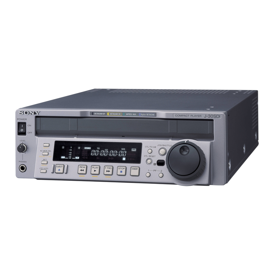
- Page 1 COMPACT PLAYER J-10 J-10SDI J-30 J-30SDI OPERATION MANUAL 1st Edition (J-30/30SDI) (J-30/30SDI) [English]...
-
Page 2: Important Safety Instructions
WARNING To prevent fire or shock hazard, do not expose the unit to rain or moisture. To avoid electrical shock, do not open the cabinet. Refer servicing to qualified personnel only. WARNING THIS APPARATUS MUST BE EARTHED. This symbol is intended to alert the user to the presence of uninsulated “dangerous voltage”... - Page 3 CAUTION Danger of explosion if battery is incorrectly replaced. Replace only with the same or equivalent type recommended by the manufacturer. Dispose of used batteries according to the manufacturer’s instructions. CAUTION The apparatus shall not be exposed to dripping or splashing and no objects filled with liquid, such as vases, shall be placed on the apparatus.
- Page 4 Pour les clients européens Ce produit portant la marque CE est conforme à la fois à la Directive sur la compatibilité électromagnétique (EMC) (89/ 336/CEE) et à la Directive sur les basses tensions (73/23/ CEE) émises par la Commission de la Communauté européenne.
-
Page 5: Table Of Contents
Table of Contents Chapter 1 Overview Chapter 2 Location and Function of Parts Chapter 3 Preparations Chapter 4 Playback Chapter 5 UMID Functions Chapter 6 Essence Marks Chapter 7 Setup Menu 1-1 Before Using ... 1-1 1-2 Features ... 1-2 1-3 Sample System Configuration ... - Page 6 Table of Contents Chapter 8 Maintenance and Inspection Appendix Table of Contents 8-1 Removing a Cassette When Tape Slack Occurs ... 8-1 8-2 Head Cleaning ... 8-1 8-3 Moisture Condensation ... 8-2 8-4 Error Messages ... 8-3 8-5 Digital Hours Meter ... 8-4 Specifications ...
-
Page 7: Overview
1-1 Before Using When using this unit for the first time, set the number of scan lines to the NTSC (525 scan lines, field frequency 60 Hz) system setting or to the PAL (625 scan lines, field frequency 50 Hz) system setting according to the operating environment in which the unit will be used. -
Page 8: Features
1-2 Features The J-10/10SDI/30/30SDI (also referred to simply as the unit(s) in this manual) are compact players based on the -inch tape format. They play tapes recorded in conventional Betacam/ Betacam SP format. Notes • Since the unit does not have a dynamic tracking function, the tape may not replay correctly if the recording pattern on the tape are disturbed. -
Page 9: Specifications
This unit can output digital video/audio signals in DV format compatible with i.LINK from the DV output connector. is a trademark of Sony Corporation and indicates that this product is in agreement with IEEE 1394-1995 specifications and their revisions. Chapter 1 Overview... -
Page 10: Sample System Configuration
1-3 Sample System Configuration Example for the J-10/10SDI Betacam SX camcorder Digital cassette J-10/10SDI EXT SYNC Reference video signal generator SDI (J-10SDI) RS-422A Server SDI (J-10SDI) S video/analog composite/ analog component (J-10) Computer Note Editing through this unit is not recommended. Chapter 1 Overview Betacam SP camcorder Analog cassette... - Page 11 Example for the J-30/30SDI MPEG IMX camcorder Betacam SX camcorder Digital cassette J-30/30SDI EXT SYNC Reference video signal generator SDI (J-30SDI) RS-422A Server SDI (J-30SDI) S video/analog composite/ analog component (J-30) Computer Note Editing through this unit is not recommended. Digital Betacam MPEG IMX cassette cassette...
-
Page 12: Location And Function Of Parts
2-1 Control Panel 1 Carrying handle 2 POWER switch 6 PHONES jack and control knob 1 Carrying handle Use this handle to carry the unit or to stand the unit vertically. Location and Function of Parts Display section (See page 2-2) 3 Cassette compartment Tape transport control section (See page 2-7) -
Page 13: Display Section
2-1 Control Panel 3 Cassette compartment Insert an S or L cassette. 4 Remote control detector Receives the infrared signal from the supplied Remote Commander. For details on the Remote Commander, see section 4-3 “Using the Remote Commander” on page 4-6. 5 PF (programmable function)-1/2 buttons When using the Betacam SX or MPEG IMX format and settting this unit into noiseless mode, use these... - Page 14 2 SET/MENU button Use this button for setup menu operations and settings. Press the SET/MENU button while holding down the SHIFT button to display the contents of the setup menu items on the FL display. When the setting is finished, press only the SET/MENU button to fix the settings and return to the normal display.
- Page 15 2-1 Control Panel Press this button while holding down the SHIFT button to function the DOLBY C NR button. The DOLBY C NR indicator lights in the display section. When you are using an oxide tape, it switches the Dolby NR C-type system for analog audio on or off. When you are using a metal tape, the Dolby C NR system is automatically switched on, regardless of the setting of this switch.
- Page 16 Audio monitor display area Time data display area Audio monitor display area • L/R audio level meter Indicates the audio levels of the 2 optionally selected channels making up L/R (Left/Right). • L/R audio channel display Indicates the optionally selected channel numbers. Time data display area Normally this displays a CTL count, time code value, or user bit value according to the selection of the CTL/...
-
Page 17: Search Control Section
2-1 Control Panel Tape transport indicator area • Tape transport indicator When you press each button in the tape transport control section, the corresponding indicators light. m: REW (rewind) indicator B: PLAY indicator When AUTO TRACKING (the automatic tape loading function) is in operation, this indicator flashes. -
Page 18: Tape Transport Control Section
• If the unit carries out reverse playback in the shuttle mode at –0.5 times or less normal speed for 20 consecutive minutes, the reel motor heat protection circuit automatically functions and the unit enters still mode. 2-1-3 Tape Transport Control Section 1 EJECT button 2 REW button... -
Page 19: Connector Panel
3 REMOTE IN (9P) connector (RS-422A serial interface, 9-pin) Controls the unit remotely from an external device equipped with the Sony 9-pin remote control function. 4 EXT SYNC (external synchronization) input connector Inputs the reference video signal. However, on this unit, use this for frame synchronization only, not for color subcarrier synchronization. - Page 20 • The i.LINK (DV) output of this unit is used to provide materials to a computer on which non- linear editing software is installed. You can use a Sony VTR equiped with an i.LINK (DV) connector (DVCAM series of VTRs for example) with this unit, though, the auto dubbing function and editing function will not be available.
-
Page 21: Connector Panel Of The J-10Sdi/30Sdi
3 REMOTE IN (9P) connector (RS-422A serial interface, 9-pin) Controls the unit remotely from an external device equipped with the Sony 9-pin remote control function. 4 EXT SYNC (external synchronization) input connector Inputs the reference video signal. However, on this unit, use this for frame synchronization only, not for color subcarrier synchronization. - Page 22 • The i.LINK (DV) output of this unit is used to provide materials to a computer on which non- linear editing software is installed. You can use a Sony VTR equiped with an i.LINK (DV) connector (DVCAM series of VTRs for example) with this unit, though, the auto dubbing function and editing function will not be available.
-
Page 23: Preparations
3-1 Installation You can install this unit horizontally as well as vertically. However, it is necessary to use the supplied vertical installation stands to prepare the unit for vertical installation as shown in the figure. Notes • When you install this unit vertically, be sure that the handle faces up. -
Page 24: Cassettes
3-2 Cassettes Cassette types This unit uses the following -inch tape width cassettes: • Digital Betacam cassette (J-30/30SDI only) • MPEG IMX cassette (J-30/30SDI only) • Betacam SX cassette • Betacam SP cassette • Betacam cassette • UVW cassette Inserting and ejecting cassettes Insert or eject a cassette while the unit is powered on. -
Page 25: Playback
TRACKING ON). You can turn auto-tracking off. For details on how to change the setting, contact your nearest Sony dealer. While this unit is pulling the tape in, the PLAY button indicator B flashes. When using the Dolby C NR system When using an analog Betacam cassette, you can use Dolby C NR for audio playback. -
Page 26: Playback In Jog Mode
4-1 Playback Procedures 4-1-2 Playback in Jog Mode In jog mode, the JOG dial controls the playback speed based the speed at which the dial is turned. The playback speed range is ±1 times normal speed. Use the following procedure to carry out playback in jog mode. -
Page 27: Noiseless Playback Function And Frame Step Playback Function
Turn the SHUTTLE dial to the angle corresponding to the desired playback speed. Playback in shuttle mode starts. Return the SHUTTLE dial to the center indent position or press the STOP button to cancel shuttle mode playback. It is possible to make pressing the JOG/SHUTTLE button to switching between JOG and SHUTTLE mode. - Page 28 4-1 Playback Procedures To perform frame step playback Put the unit into noiseless mode and press the PF-1 or PF-2 button. When you are using the Betacam SX format, each press of the PF-1 button steps 2 frames back, and each press of the PF-2 button steps 2 frames forward.
-
Page 29: Superimposed Character Information
4-2 Superimposed Character Information 1 Types of time data Time data 2 Drop frame mark of time data 4 Operation mode When basic menu item 005 of the setup menu DISPLAY INFORMATION SELECT is set as anything other than OFF, the video signal output from the COMPOSITE (SUPER) output connector, SDI (SUPER) output connector (for J-10SDI/30SDI only) or DV connector contains superimposed character... -
Page 30: Using The Remote Commander
4-3 Using the Remote Commander 4-1 Playback Procedures Pull off the transparent film covering the battery parts. 4-3-1 How to Change the Lithium Battery Pull out the lithium battery case. Pull the battery case toward you while releasing the lock by plucking it with your fingernail. Set lithium battery in the case so that the + symbol on the battery is facing you. -
Page 31: Operating The Remote Commander
Turn the JOG/SHUTTLE dial to change the setting from “OFF” to “ON” while holding down the JOG/ SHUTTLE button, and then release the JOG/ SHUTTLE button. Time data display area Monitor screen REMOTE INTERFACE 213:WIRELESS-on Items without are omitted. (ON flashes while the JOG/SHUTTLE button is being pressed.) Press the SET/MENU button. -
Page 32: Operation Via Computer (With The Jz-1 Software)
4-4 Operation via Computer (With the JZ-1 Software) 4-1 Playback Procedures The following operations will be available when using the unit connected to a computer with the optional JZ- 1 software installed. • Controlling basic operations such as play, fast forward, rewind, stop, jog playback, and shuttle playback via the computer •... -
Page 33: Umid Functions
5-1 Overview of UMID Functions The UMID (Unique Material Identifier) is a type of meta-data in video and audio materials. It has been internationally standardized in SMPTE Standard 330M. This unit supports generation of UMIDs recorded in the Digital Betacam or MPEG IMX format. -
Page 34: Umid Output And Display
5-2 UMID Output and Display This section explains how to output and display UMIDs. 5-2-1 UMID Output Settings You can choose to output UMIDs or not from the SDI or SDI (SUPER) output connector, and select either Basic UMID or Extended UMID when you choose to output UMIDs. -
Page 35: Essence Marks
Chapter Essence Marks 6-1 Overview of Essence Mark Functions An essence mark uses a term value dictionary item as defined in the SMPTE RP210A Metadata Dictionary to express and transfer points such as recording start points and edit point candidates in up to 32 bytes of data. -
Page 36: Essence Mark Output
6-2 Essence Mark Output 5-2 Menu Operations When playing back a tape, essence marks recorder on the tape can be output to SDI signals. Information such as shot marks recorded on the tape can also be converted into essence marks and output. Selecting whether to output essence marks You can select whether or not to output essence marks... -
Page 37: Setup Menu
7-1 Menu System Configuration The principal setup operations required before operating this unit can be carried out using setup menus. The menu system of this unit is comprised of a basic menu and an extended menu. • Basic menu This menu is used to make the following settings: –... -
Page 38: Menu Operations
7-2 Menu Operations 7-2 Menu Operations This section describes the basic menu displays and how to change the settings. For information about how to use basic menu item 013, see “Switching between 525/625 line systems (basic menu item 013)” on page 7-4, and for information about how to operate items B01 to B12, see “Menu bank operations (basic menu items B01 to B12)”... - Page 39 Changing a menu item setting value To change the setting value of the currently displayed menu item, use the following procedure. Holding down the JOG/SHUTTLE button, turn the JOG/SHUTTLE dial. The setting value changes at a rate based on the SHUTTLE dial position or on the JOG dial rotation rate.
- Page 40 7-2 Menu Operations Switching between 525/625 line systems (basic menu item 013) Using the following procedure, you can set basic menu item 013, 525/625 SYSTEM SELECT, to ON, and then switch between 525 (NTSC) and 625 (PAL). (The following is the procedure example of switching from a 525 (NTSC) system to a 625 (PAL) system.) Select basic menu item 013 and display it.
- Page 41 Holding down the JOG/SHUTTLE button, turn the JOG/SHUTTLE dial to change the setting from 525 to 625. The displays change as follows. Time data display area Monitor screen 525/625 SYSTEM SELECT Push SET button!! To cancel the 525/625 setting operation Holding down the SHIFT button, press the SET/ MENU button the required number of times to exit from the menu.
- Page 42 7-2 Menu Operations Extended menu operations You can operate the extended menu in the same way as you operate the basic menu. For details of basic menu operations, see page 7-2. Note To access the extended menu, it is required to set MENU GRADE, basic menu item 099, to ENHAN.
-
Page 43: Basic Menu
7-3 Basic Menu The basic menu contains the following items. In the “Settings” column of the table, the factory Item number Item name CHARACTER H- POSITION a), b) CHARACTER V- POSITION DISPLAY INFORMATION SELECT TAPE TIMER DISPLAY CHARACTER TYPE CHARACTER V-SIZE a) When setting items 002, 003, 009 and 011 watch the monitor screen, and adjust to the required state. - Page 44 7-3 Basic Menu Item number Item name CONDITION DISPLAY ON VIDEO MONITOR (The channel status can be displayed only when the CHARACTER V-SIZE is set to 1.) 525/625 SYSTEM SELECT DROP-FRAME MODE SELECT (When operating in 525 mode) PF2 KEY SELECT MENU CHARACTER TYPE NOISELESS PB MODE...
- Page 45 Item number Item name SDI OUT CHARACTER (J-10SDI/30SDI only) i.LINK CHARACTER Item number Item name MENU GRADE RECALL BANK 1 RECALL BANK 2 SAVE BANK 1 SAVE BANK 2 RESET SETUP Settings Select whether or not to superimpose the type of characters over the video signal (overlap display) output from the SDI (SUPER) connectors.
-
Page 46: Extended Menu
7-4 Extended Menu 7-4 Extended Menu The extended menu contains the following items. In the “Settings” column of the table, the factory default settings are indicated by an enclosing box. Item number Item name SELECTION FOR JOG/ SHUTTLE DIAL ENABLE MAXIMUM TAPE SPEED AUDIO MUTING TIME REFERENCE SYSTEM... - Page 47 Item number Item name STILL TIMER UMID OUTPUT (J-30SDI only) ESSENCE MARK TAPE OUTPUT (J-30SDI only) SHOT MARK ESSENCE MARK CONVERT (J-10SDI/30SDI only) ESSENCE MARK VANC LINE (J-10SDI/30SDI only) INTERNAL VIDEO SIGNAL GENERATOR VIDEO SETUP REFERENCE LEVEL (When operating in 525 mode) VIDEO GAIN CONTROL CHROMA GAIN...
- Page 48 7-4 Extended Menu Item number Item name SYSTEM PHASE SYNC Y/C DELAY DIGITAL AUDIO MUTE IN SHUTTLE MODE INTERNAL AUDIO SIGNAL GENERATOR i.LINK AUDIO OUTPUT SELECT VIDEO OUTPUT DATA (J-10SDI/30SDI only) IMX NOISELESS PB SELECT (J-30/30SDI only) a) Audio signals are muted if you select the channel unavailable for the format you are using.
-
Page 49: Maintenance And Inspection
See the maintenance manual for details. 8-2 Head Cleaning To clean the video heads and audio heads, always use the special-purpose Sony BCT-HD12CL cleaning cassette. Follow the instructions with the cleaning cassette carefully, as inappropriate use of the cleaning cassette can damage the heads. -
Page 50: Moisture Condensation
8-3 Moisture Condensation 8-1 Removing a Cassette When Tape Slack Occurs When the unit is suddenly moved from a cold to a warm location, or used in a very humid place, moisture from the air can condense on the head-drum. This is called moisture condensation. -
Page 51: Error Messages
8-4 Error Messages CODE MESSAGE ERRORS REEL TROUBLE Detected “tape slack” during threading or unthreading. REEL TROUBLE Detected “tape slack” or “tape break” during search, fast-forward, or rewind. REEL TROUBLE Detected “tape slack,” “tape break,” or “reel rock in the S-side or T-side” during playback. REEL TROUBLE Detected abnormal tape speed during fast-forward or rewind. -
Page 52: Digital Hours Meter
8-5 Digital Hours Meter 8-1 Removing a Cassette When Tape Slack Occurs The digital hours meter can display nine items of information, in corresponding display modes, about the operational history of the unit. Use it as a guide in scheduling periodic maintenance. Display modes of the digital hours meter The digital hours meter has the following nine modes. -
Page 53: Appendix
Specifications General Power requirements 100 to 240 VAC, 50/60 Hz Power consumption 55 W Rated current 0.55 A Peak inrush current (1) Power ON, current probe method: 40 A (240 V), 10 A (100 V) (2) Hot switching inrush current, measured in accordance with European standard EN55103-1: 15 A (230 V) Operating temperature... -
Page 54: Specifications
Specifications Jog mode Still to ±1 times normal playback speed Servo lock time (from standby) 1.5 second or less Load/unload time 7 seconds or less Cassette types Digital Betacam cassette (J-30/ 30SDI) MPEG IMX cassette (J-30/30SDI) Betacam SX cassette Betacam SP cassette Betacam cassette UVW cassette Digital video system... - Page 55 Remote connectors RS232C D-sub 9-pin, male, Sony 9-pin Remote Interface REMOTE IN (9P) D-sub 9-pin, female, Sony 9-pin Remote Interface Input connector EXT SYNC BNC (1), Frame lock Input/output connectors of J-10SDI/30SDI Output connectors COMPOSITE (SUPER) BNC (1), Phono jack (1), including character superimposition 1.0 Vp-p, 75 , Sync negative...
- Page 56 The material contained in this manual consists of information that is the property of Sony Corporation and is intended solely for use by the purchasers of the equipment described in this manual. Sony Corporation expressly prohibits the duplication of any...
- Page 57 Sony Corporation J-10/10SDI/ B & P Company 30/30SDI (SY) 3-826-997-01(1) 2004...