Sony Walkman WM-EX170 Service Manual
Hide thumbs
Also See for Walkman WM-EX170:
- Operating instructions (2 pages) ,
- Operating instructions (2 pages)
Table of Contents
Advertisement
Quick Links
WM-EX170/EX172
SERVICE MANUAL
Manufactured under license from Dolby Laboratories
Licensing Corporation.
"DOLBY" and the double-D symbol a are trademarks
of Dolby Laboratories Licensing Corporation.
MICROFILM
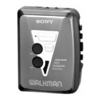
Photo : WM-EX172
SPECIFICATIONS
• Power requirements
3V DC batteries R6 (AA) × 2 / External DC 3V power sources
• Dimensions
88.5 × 111.5 × 37.6 mm
× 4
× 1
1
1
1
(3
/
/
/
inches) (w / h/ d) incl. projecting parts and controls
2
2
2
• Mass
EX170 : Approx. 125 g (4.5 oz) / Approx. 185 g (6.6 oz) incl.
batteries and a cassette
EX172 : Approx. 130 g (4.6 oz) / Approx. 190g (6.8 oz) incl.
batteries and a cassette
• Supplied accessories
Stereo headphones or Stereo earphones (1) / Belt clip (1)
Design and specifications are subject to change without notice.
Canadian Model
Model Name Using Similar Mechanism
Tape Transport Mechanism Type
CASSETTE PLAYER
WM-EX170
AEP Model
E Model
WM-EX170/172
NEW
MT-WMEX170-114
Advertisement
Table of Contents

Related Manuals for Sony Walkman WM-EX170


Summary of Contents for Sony Walkman WM-EX170
- Page 1 WM-EX170/EX172 SERVICE MANUAL Canadian Model WM-EX170 AEP Model E Model WM-EX170/172 Photo : WM-EX172 Manufactured under license from Dolby Laboratories Model Name Using Similar Mechanism Licensing Corporation. Tape Transport Mechanism Type MT-WMEX170-114 “DOLBY” and the double-D symbol a are trademarks of Dolby Laboratories Licensing Corporation.
-
Page 2: Table Of Contents
TABLE OF CONTENTS Flexible Circuit Board Repairing GENERAL ······································································ 2 • Keep the temperature of the soldering iron aroud 270˚ C during repairing. DISASSEMBLY • Do not touch the soldering iron on the same conductor of the 2-1. Cabinet (Front) Assy ·························································· 3 circuit board (within 3 times). -
Page 3: Disassembly
SECTION 2 DISASSEMBLY • This set can be disassembled in the order shown below. 2-1. CABINET (FRONT) ASSY 2-2. MAIN BOARD 2-4. MECHANISM DECK 2-5. BELT, MOTOR (REEL/CAPSTAN) 2-3. CASSETTE LID Note : Follow the disassembly procedure in the numerical order given. 2-1. -
Page 4: Main Board
2-2. MAIN BOARD 3 Remove the four solders. 4 Screw (M1.4), toothed lock (WH) 2 Flexible board (CN302) 6 MAIN board 5 Two claws 1 Head flexible board (CN301) 2-3. CASSETTE LID 2 Insert a precision screwdriver (1.4 mm flat-blade) vertically into portion A to release the 5 Spring (torsion) hinge plate. -
Page 5: Mechanism Deck
2-4. MECHANISM DECK 2 Remove the mechanism deck in the direction of the arrow. 1 Insert the precision screwdriver (1.4 mm flat-blabe) in to the slit and release two claws. 2-5. BELT, MOTOR (REEL/CAPSTAN) 2 Two screw [screw (M1.4), special head] 3 Motor (reel/capstan) 1 Belt —... -
Page 6: Mechanical Adjustment
SECTION 3 SECTION 4 MECHANICAL ADJUSTMENT ELECTRICAL ADJUSTMENT PRECAUTION PRECAUTION Clean the following parts with a denatured-alcahol-moistened Specified voltage : 3.0V sweb : Switch position Playback head Pinch roller DOLBY NR switch : OFF (EX172 MODEL) Rubber belt Capstan AVLS switch : NORM Demagnetize the playback head using a demagnetizer. -
Page 7: Diagrams
WM-EX170/EX172 SECTION 5 DIAGRAMS 5-1. BLOCK DIAGRAM MAIN BOARD EX172 MODEL EX170 MODEL MEGA BASS UNIT MEGA BASS UNIT S352 S351 S351 RV351 RV352 DOLBY NR MEGA BASS MEGA BASS HIGH ON – OFF OFF – ON OFF – ON... -
Page 8: Printed Wiring Board (Ex170 Model)
WM-EX170/EX172 5-2. PRINTED WIRING BOARD (EX170 MODEL) • Semiconductor Location MEGA BASS UNIT Ref. No. Location M901 REEL/CAPSTAN D150 MOTOR IC301 IC601 E-10 DRY BATTERY SIZE "AA" (IEC DESIGNATION R6) 2PCS, 3V MAIN BOARD EXCEPT E,9E J302 E,9E MODEL AVLS... -
Page 9: Schematic Diagram (Ex170 Model)
WM-EX170/EX172 5-3. SCHEMATIC DIAGRAM (EX170 MODEL) Note on Schematic Diagram: • All capacitors are in µF unless otherwise noted. pF: µµF • Voltages are taken with a VOM (Input impedance 10 MΩ). 50 WV or less are not indicated except for electrolytics Voltage variations may be noted due to normal produc- and tantalums. -
Page 10: Printed Wiring Board (Ex172 Model)
WM-EX170/EX172 5-4. PRINTED WIRING BOARD (EX172 MODEL) MEGA BASS UNIT • Semiconductor Location RV351 Ref. No. Location HIGH D150 RV352 M901 IC301 REEL/CAPSTAN IC331 MOTOR IC601 E-10 S351 MEGA BASS DRY BATTERY SIZE "AA" S352 (IEC DESIGNATION R6) DOLBY NR... -
Page 11: Schematic Diagram (Ex172 Model)
WM-EX170/EX172 5-5. SCHEMATIC DIAGRAM (EX172 MODEL) Note on Schematic Diagram: • All capacitors are in µF unless otherwise noted. pF: µµF Voltage variations may be noted due to normal produc- 50 WV or less are not indicated except for electrolytics tion tolerances. -
Page 12: Ic Block Diagrams
5-6. IC BLOCK DIAGRAMS IC331 NJM2185V VEXT OUTA DETA – Weight BIAS Circuit – Ach BLOCK Bch BLOCK (same Ach) IREF VREF OUTB DETB IC601 LB1979V POWER SUPPLY OSCILLATOR CURRENT DETECT CIRCUIT BIAS REFERENCE SPEED VOLTAGE DETECT REFERENCE VOLTAGE FOR SPEED CONTROL OUTPUT WAVEFORM DETECT... -
Page 13: Exploded Views
SECTION 6 EXPLODED VIEWS NOTE: • The mechanical parts with no reference number : Central and South America. • -XX, -X mean standardized parts, so they may have some differences from the original one. in the exploded views are not supplied. : Country of origin is not shown. -
Page 14: Main Board Section
6-2. MAIN BOARD SECTION MT-WMEX170-114 Ref. No. Part No. Description Remarks Ref. No. Part No. Description Remarks 3-015-285-01 SCREW (M1.4),TOOTHED LOCK (WH) 3-019-950-01 TERMINAL (+),BATTERY A-3021-030-A MAIN BOARD, COMPLETE(EX170:E,9E) 3-019-944-01 BUTTON (STOP) A-3021-008-A MAIN BOARD, COMPLETE(EX170:CND,AEP,EE) 3-019-943-01 BUTTON (REW) A-3021-040-A MAIN BOARD, COMPLETE(EX172:E,6E,9E) 3-019-941-01 BUTTON (PLAY) A-3021-041-A MAIN BOARD, COMPLETE(EX172:FR) 3-019-942-01 BUTTON (FF) -
Page 15: Mechanism Section-1 (Mt-Wmex170-114)
6-3. MECHANISM SECTION-1 (MT-WMEX170-114) HP901 M901 Ref. No. Part No. Description Remarks Ref. No. Part No. Description Remarks 3-013-560-11 BELT 3-920-996-01 SPRING (PINCH N) 3-703-816-31 SCREW (M1.4), SPECIAL HEAD M901 1-763-073-11 MOTOR 3-019-776-01 GEAR (REEL-S) HP901 1-500-517-11 HEAD, MAGNETIC (PLAYBACK) 3-703-816-73 SCREW (M1.4), SPECIAL HEAD X-3369-749-1 PINCH LEVER (N) ASSY —... -
Page 16: Mechanism Section-2 (Mt-Wmex170-114)
6-4. MECHANISM SECTION-2 (MT-WMEX170-114) Ref. No. Part No. Description Remarks Ref. No. Part No. Description Remarks 3-921-797-01 WASHER 3-921-335-01 WASHER, LEVER 3-921-003-01 BEARING 3-920-990-01 SPRING (UD), COMPRESSION 3-938-628-01 SPRING (PLAY-CP) 3-019-774-01 GEAR (BS) 3-019-773-01 GEAR (AS) X-3369-747-1 WHEEL ASSY (SP), CAPSTAN X-3374-598-1 CLUTCH ASSY (S) 3-019-775-01 GEAR (DS) 3-022-093-01 SPRING (FR-S) -
Page 17: Electrical Parts List
SECTION 7 MAIN ELECTRICAL PARTS LIST NOTE: • Items marked “*” are not stocked since they • COILS are seldom required for routine service. Some uH: µH When indicating parts by reference number, delay should be anticipated when ordering these •... - Page 18 MAIN Ref. No. Part No. Description Remarks Ref. No. Part No. Description Remarks C323 1-163-009-11 CERAMIC CHIP 0.001uF JR313 1-216-296-91 SHORT C324 1-163-009-11 CERAMIC CHIP 0.001uF JR314 1-216-296-91 SHORT (EX170) JR315 1-216-296-91 SHORT C324 1-163-038-91 CERAMIC CHIP 0.1uF JR316 1-216-296-91 SHORT 0 (EX172) (EX172) JR317...
- Page 19 WM-EX170/EX172 MAIN Ref. No. Part No. Description Remarks Ref. No. Part No. Description Remarks R306 1-216-077-00 METAL CHIP 1/10W ACCESSORIES & PACKING MATERIALS (EX170) ******************************* R306 1-216-057-00 METAL CHIP 2.2K 1/10W (EX172) 1-505-521-11 HEADPHONES (MDR-023)(EXCEPT E,6E,9E) R309 1-216-113-00 METAL CHIP...