
Related Manuals for Sony HDCU3100


Summary of Contents for Sony HDCU3100
- Page 1 4-738-876-12 (1) Camera Control Unit Operating Instructions Before operating the unit, please read this manual thoroughly and retain it for future reference. HDCU3100 HDCU3170 © 2018 Sony Corporation...
-
Page 2: Table Of Contents
Status Display Screen ...........13 Menu Settings ............15 Changing Menu Item Settings ........15 Menu Tree ..............17 Menu List ...............21 Appendix ..............47 Precautions ..............47 Digital Triax Transmission (HDCU3170) .......47 Error Messages .............47 Specifications ............48 HDCU3100/HDCU3170 ..........48 HKCU-FB30 ..............49 HKCU-SFP30 ..............49 HKCU-SM30 ..............50... -
Page 3: Overview
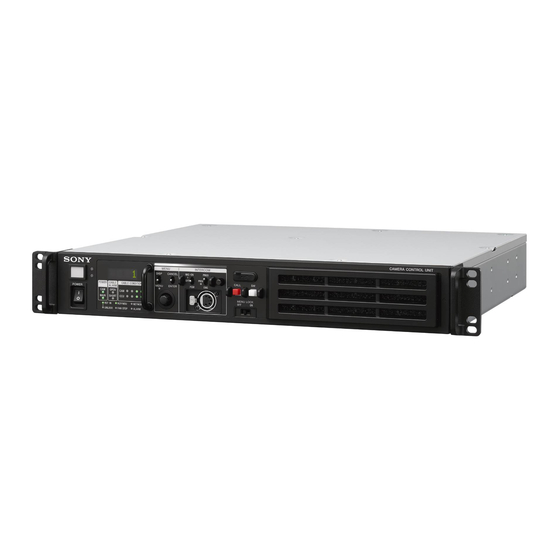
Overview The HDCU3100 Camera Control Unit connects to an HDC3500 Color Camera, HDC3100 Fiber Color Camera, or HDC2000-series or HSC300RF/100RF HD Color Camera, with an optical fiber cable, and carries out signal processing, provides an interface with external equipment, and supplies power to the camera. -
Page 4: System Configuration
System Configuration Note Production of some of the peripherals and related devices shown in the figures may have been discontinued. For advice on choosing devices, please contact your Sony representative or dealer. Connection example (optical fiber transmission) HDVF-EL75/L750/L770 Viewfinder HDVF-200... - Page 5 Connection example (digital triax transmission) HDVF-EL75/L750/L770 Viewfinder HDVF-200 HDVF-EL20 BKW-401 Viewfinder HDVF-EL30 Rotation Bracket Viewfinder Lens HDC3500 Color Camera (for ENG/EFP) HDC3170 Triax Color Camera Sync signal input USB flash drive Return video input CAC-6 Intercom microphone input VCT-14 Return Video Selector Tripod Adaptor 2K Video Intercom Headset...
- Page 6 SNMP Manager IP switch Ember+ software a) Set the signal transfer rate according to the connected camera using the following menu in the HDCU3100/HDCU3170. SYSTEM CONFIG <CAMERA I/F> (page 21) b) Signal transfer up to a maximum of 2 km is possible. However, the actual transfer distance may vary depending on the system configuration of the cameras and the type of optical fiber cables used.
- Page 7 HDC2000 series: HDC2000/2580/2500/2400/1700 b) Attach the HKCU-SM30 Single Mode Fiber Connector Kit. c) Configure the transmission type using the following menu item on the HDCU3100. Set SYSTEM CONFIG t <CAMERA I/F> t CABLE TYPE to SINGLE-MODE FIBER. d) Signal transfer up to a maximum of 10 km is possible. However, the actual transfer distance may vary depending on the system configuration of the...
-
Page 8: Location And Function Of Parts
OPEN: Lights up when a camera is not connected to the CAMERA FIBER connector on the rear panel of this unit Note via an optical fiber cable (HDCU3100) or to the CAMERA TRIAX connector via a triax cable (HDCU3170). Power is Do not pull the guard bar with excessive force. - Page 9 n Assignable button • CANCEL/ENTER lever In setup menu mode, used to cancel and enter settings. You can set a function for this button via the CCU menu. • Control knob (rotary encoder) o Filter cover In status screen mode, used to change the displayed page. In Press the filter cover in the direction of the arrow while pulling setup menu mode, used to move the cursor on a page and to it to remove it.
-
Page 10: Rear Panel
MSU-1000 series Master Setup Unit. c Option kit mounting port For details on the setup menu, contact a Sony service or sales One of the following option kits can be attached. representative. • HKCU-SFP30 ST-2110 Interface Kit •... - Page 11 Refer also to the Master Setup Unit manual. m - AC IN (AC power input) connector For details on how to select the signal, contact a Sony service or sales representative. Use the specified AC power cord to connect to an AC power supply.
-
Page 12: Option Kits
Option Kits This unit is an option kit that can be installed in the option kit mounting port k on the rear of the HDCU3100 Camera Note Control Unit or in the option kit mounting port c on the rear of the HDCU3170, and supports single mode fiber transmission. -
Page 13: Status Display
Camera settings Status Display HDC3500 HJ22eX7.6B F:4.7 The CCU system status can be monitored using a video monitor connected to the CHARACTER, SDI OUT 3, or SDI OUT 4 connector. Note To use the SDI OUT 3 or SDI OUT 4 connector, set SYSTEM CONFIG t <OUTPUT FORMAT1>... - Page 14 IP-OUT connectors System status * Sy s t e m S ta t us * 0 1 / 0 6 Ca m e r a F or m at : 10 8 0 / 5 9 . 9 4 P Ca m e r a C ab l e : Co n n e c t e d C a b l e T yp e...
-
Page 15: Menu Settings
Warning display Menu Settings * Al a r m * 0 6 / 0 6 CC U : P S F A N S T O P CC U : G E N L O C K E R R O R The CCU system and peripheral settings can be checked and modified using a video monitor connected to the CHARACTER, SDI OUT 3, or SDI OUT 4 connector. - Page 16 Press the CONTROL knob. Menu name Description AUDIO/INTERCOM Audio- and intercom-related The question mark (?) changes back to the pointer (,), settings and the item setting is registered. MAINTENANCE CCU configuration settings Repeat steps 1 to 3 to change other settings on the same FILE CCU file-related settings page.
-
Page 17: Menu Tree
Menu Tree SYSTEM CONFIG menu OUTPUT FORMAT2 SDI-I/O1 (S08) MONITOR Note FORMAT OETF Items marked with “a)” are not available on the HDCU3170 in COLOR triax transmission mode. SDI-I/O2 MONITOR FORMAT CAMERA I/F CABLE TYPE OETF (S01) FIBER TRANSMIT RATE COLOR OPTICAL SIGNAL SDI-I/O3... - Page 18 VIDEO/MONITOR menu AUDIO/INTERCOM menu Note MIC GAIN CAM MIC GAIN Items marked with “a)” are not available on the HDCU3170 in (A01) triax transmission mode. AUDIO OUT DELAY (A02) AES/EBU OUT ANALOG OUT COLOR BAR 4K/HD-BAR SELECT CH1 : LEVEL (V01) MF-CB CH1 : ADJUST...
- Page 19 MAINTENANCE menu NETWORK menu Note IP ADDRESS PORT Items marked with “a)” are not available on the HDCU3170 in (N01) DHCP IP ADDRESS triax transmission mode. SUBNET MASK DEFAULT GATEWAY TRUNK/PROMPTER TRUNK LINE MAC ADDRESS (M01) CHANNEL MODE LINK SPEED INTERFACE 25G FEC PROMPTER...
- Page 20 DIAGNOSIS menu MULTICAST MULTICAST ADDRESS ADDRESS 4 (N08) INTERCOM OUT LAN1 IP ADDRESS BOARD STATUS PORT (D01) INTERCOM OUT LAN2 INTERCOM IN LAN1 POWER ON HOUR METER IP ADDRESS HOUR METER PORT SERIAL NUMBER MODEL NAME SRC IP (D02) SERIAL NUMBER INTERCOM IN LAN2 VERSION APPLICATION...
-
Page 21: Menu List
Specifies the cable type used for connecting the COAX(HDCE), SINGLE-MODE camera. FIBER, TRIAX CAMERA CABLE FIBER CAMERA CABLE: Select when using the HDCU3100 or when using the HDCU3170 with HKCU-FB30 installed. TRIAX CAMERA CABLE: Select when using the HDCU3170. SINGLE-MODE FIBER: Selectable only when the HKCU-SM30 is installed. - Page 22 SYSTEM CONFIG Page name Item Set value Description Page No. <VIDEO I/O> SDI-I/O 1 Sets SDI I/O 1. IN, OUT Selects input or output. SIGNAL When OUT is selected in I/O: Sets the signal function. (SDI-OUT) When IN is selected in I/O: (SDI-RET) SDI-I/O 2 Sets SDI I/O 2.
- Page 23 SYSTEM CONFIG Page name Item Set value Description Page No. <GENLOCK> REFERENCE NOT DETECTED, EXT IN, 1080/ Signal input of the REFERENCE IN connector. 59.94I, 1080/23.98PsF, 720/ (Display only) 59.94P, 1080/50I, 1080/24PsF, 720/50P LOCK STATUS When HD or SD is selected in Lock status of the external reference signal.
- Page 24 SYSTEM CONFIG Page name Item Set value Description Page No. <MULTI FORMAT> SYSTEM 1.001(525), 1.000(625) Selects the operating frequency of the system. CAMERA FORMAT When 1.001(525) is selected in Selects the system format. SYSTEM: Only 1080/59.94P and 1080/50P are displayed when 1080/59.94P (4K/HDR), 1080/ using HDCU3170.
- Page 25 SYSTEM CONFIG Page name Item Set value Description Page No. <HDR> HDR MODE OFF, LIVE HDR OFF: Normal shooting operation. LIVE HDR: Used for LIVE HDR shooting. Note When LIVE HDR is selected, camera paint functions can be used for both HDR output and SDR output. However, some paint functions are not supported for HDR output.
- Page 26 SYSTEM CONFIG Page name Item Set value Description Page No. <OUTPUT FORMAT1> SDI-OUT3 Sets the output for the SDI OUT 3 connector. MONITOR C, M Sets whether to add characters to the output signal. C: Characters are not added. M: Characters are added. FORMAT See “Formats settable for the SDI Sets the output signal format for the SDI OUT 3...
- Page 27 SYSTEM CONFIG Page name Item Set value Description Page No. <OUTPUT FORMAT2> SDI-I/O1 Sets the output for the SDI I/O 1 connector. MONITOR Sets whether to add characters to the output signal. C: Characters are not added. Note This is fixed to C. FORMAT See “Formats settable for the SDI Sets the output signal format for the SDI I/O 1...
- Page 28 SYSTEM CONFIG Page name Item Set value Description Page No. <OUTPUT FORMAT2> SDI-I/O4 Sets the output for the SDI I/O 4 connector. MONITOR Sets whether to add characters to the output signal. C: Characters are not added. Note This is fixed to C. FORMAT See “Formats settable for the SDI Sets the output signal format for the SDI I/O 4...
- Page 29 SYSTEM CONFIG Page name Item Set value Description Page No. <OUTPUT FORMAT3> IP-OUT3 Sets the IP OUT3 connector output. MONITOR C, M Sets whether to add characters to the output signal. Displayed only when C: Characters are not added. HKCU-UHD30 is installed. M: Characters are added.
- Page 30 SYSTEM CONFIG Page name Item Set value Description Page No. <RETURN FORMAT3> IP-RET Sets the format of the return signal to be input on the LAN connectors. IP-RET1,2 1080/59.94P, 1080/50P, 1080/59.94I(PsF), 1080/50I(PsF) IP-RET3 1080/59.94I(PsF), 1080/50I(PsF) Formats settable for RETURN FORMAT SYSTEM CONFIG t HDC3500/3100 HSC300RF/100RF...
- Page 31 Formats settable for the SDI OUT / SDI I/O connectors SYSTEM CONFIG t HDC3500/3100 HSC300RF/100RF HDC3170 <MULTI FORMAT> page HDC2000 series HDC3500 with HKC-TR37 t CAMERA FORMAT attached settings (When SYSTEM CONFIG t (When SYSTEM CONFIG t (When SYSTEM CONFIG t <CAMERA I/F>...
- Page 32 SYSTEM CONFIG t HDC3500/3100 HSC300RF/100RF HDC3170 <MULTI FORMAT> page HDC2000 series HDC3500 with HKC-TR37 t CAMERA FORMAT attached settings (When SYSTEM CONFIG t (When SYSTEM CONFIG t (When SYSTEM CONFIG t <CAMERA I/F> t CABLE TYPE is <CAMERA I/F> t CABLE TYPE is <CAMERA I/F>...
- Page 33 VIDEO/MONITOR menu Note Items marked with “a)” are not available on the HDCU3170 in triax transmission mode. VIDEO/MONITOR Page name Item Set value Description Page No. <COLOR BAR> 4K/HD-BAR SELECT BAR 16:9(100%), BAR 16:9(75%), Selects the color bars of 4K output/HD output. SMPTE 16:9(BLACK), SMPTE 16:9(-I/Q), BAR 4:3(100%), BAR 4:3(75%), SMPTE 4:3(BLACK),...
- Page 34 VIDEO/MONITOR Page name Item Set value Description Page No. <MONITOR> CHARACTER LEVEL 1, 2, 3, 4, 5 Sets the brightness of text in menus, etc. LEVEL GATE OFF, 1&2, 1, 2, (---) Sets level gate display. OFF: Level gate is not displayed. 1: Displays level gate 1.
- Page 35 VIDEO/MONITOR Page name Item Set value Description Page No. <DISPLAY> MESSAGE ALL, WARNING, OFF Sets the display of messages for the camera auto setup operation status, warnings that occur in the system, etc. Sets the items to be ALL: Displays all messages. displayed on the camera setting status page of the WARNING: Displays system warning messages and...
- Page 36 AUDIO/INTERCOM Page name Item Set value Description Page No. <INTERCOM> INTERCOM CH 1CH(PROD), 2CH(PROD&ENG) Selects the intercom channel number to be used. PRODUCER CLEAR COM, 4WIRE, RTS Sets the producer line intercom system. INTERFACE SIDETONE –99 to 99 0 Sets the side tone cancel level. (Setting is possible CANCEL when CLEAR COM or RTS) TERMINATION...
- Page 37 AUDIO/INTERCOM Page name Item Set value Description Page No. <IP AUDIO> AUDIO OUT FORMAT L24/48kHz/1ms/2ch, L24/48kHz/ Sets the audio format. 1ms/4ch, L24/48kHz/1ms/8ch, Displayed only when L24/48kHz/0.125ms/2ch, L24/ HKCU-SFP30 is installed. 48kHz/0.125ms/4ch, L24/48kHz/ 0.125ms/8ch, L24/48kHz/ 0.125ms/16ch CH ORDER MIC1, MIC2, AES/EBU1, AES/ Displays the channel order.
- Page 38 MAINTENANCE menu Note Items marked with “a)” are not available on the HDCU3170 in triax transmission mode. MAINTENANCE Page name Item Set value Description Page No. <TRUNK/PROMPTER> TRUNK LINE CHANNEL MODE When <CAMERA I/F> t CABLE Sets the number of channels to be used. TYPE is FIBER CAMERA CABLE and FIBER TRANSMIT RATE is HIGH: 2CH(MAX 75Kbps),...
- Page 39 MAINTENANCE Page name Item Set value Description Page No. <MENU SETTINGS> PAGE RESUME ON, OFF Turns the menu mode resume page display function ON/OFF. ALARM JUMP ON, OFF Turns the error-related page display function ON/ OFF for when an error occurs while in menu mode. CAMERA MENU OFF, ON Displays the Camera menu.
- Page 40 Saves the CCU file to the internal memory. EXPORT Exports the CCU file to the USB flash drive. The path for the USB flash drive is “/MSSONY/PRO/ CAMERA/HDCU3100.” IMPORT Imports the CCU file from the USB flash drive. The path for the USB flash drive is “/MSSONY/PRO/ CAMERA/HDCU3100.”...
- Page 41 NETWORK Page name Item Set value Description Page No. <CNS SETTINGS> CNS MODE LEGACY, BRIDGE, MCS Sets the communication mode. MCS MODE CLIENT Indicates that the unit is the client when MCS mode is selected. (Display only) CCU NO When MCS is selected in CNS Sets the CCU number.
- Page 42 NETWORK Page name Item Set value Description Page No. <IP LIVE> IP LIVE SYSTEM MANAGER PORT DISABLE, LAN1&LAN2 Sets the IP Live System Manager (LSM). Displayed only when DISABLE: Do not communicated with LSM. HKCU-SFP30 is installed. LAN1&LAN2: Redundancy communication with LAN-1 and LAN-2.
- Page 43 NETWORK Page name Item Set value Description Page No. <MULTICAST ADDRESS MULTICAST AUTO, MANUAL Displays the MULTICAST ADDRESS setting of the 3> ADDRESS <MULTICAST SETTING> page. AUDIO OUT LAN1 Displayed only when IP ADDRESS 224.0.0.1 to 239.255.255.255 Displays the destination IP address. HKCU-SFP30 is installed.
- Page 44 ENABLE, DISABLE Enables/disables SNMP V1. ENABLE ENABLE, DISABLE Enables/disables SNMP V2C. V1/V2C RO COMMUNITY sony Displays the ReadOnly community name (ASCII code, up to 32 characters). ALLOW HOST ANY, SPECIFIC Sets the hosts that can be connected. ANY: Allow access from all IP addresses.
- Page 45 NETWORK Page name Item Set value Description Page No. <PING> PORT LAN-COM Selects the PING transmission destination port. IP ADDRESS 0.0.0.0 to 255.255.255.255 Sets the IP address for the PING transmission destination port. PING PING transmission. (Execute via EXEC.) STATISTICS Displays the PING execution results.
- Page 46 DIAGNOSIS Page name Item Display Description Page No. <FAN STATUS> PS FAN OK, STOP Displays the power supply unit fan operation status. REAR FAN OK, STOP Displays the rear panel fan operation status. FRONT FAN1 OK, STOP Displays the front panel fan 1 operation status. FRONT FAN2 OK, STOP Displays the front panel fan 2 operation status.
-
Page 47: Appendix
Digital Triax Transmission (HDCU3170) Appendix A powerful error-correction function is incorporated for the transmission between the camera and CCU. However, if an error occurs on long-distance transmission because of Precautions external noise or for some other reason, the compensation by interpolation that partially uses the previous picture may If the unit is suddenly taken from a cold to a warm location, or operate. -
Page 48: Specifications
CCU:FORCE LEGACY FORCE LEGACY is set for CNS MODE Mass HDCU3100: Approx. 7.3 kg (16 lb 1.5 oz) CCU:10FIELD-ID ERROR 10-field ID is not detected even HDCU3170: Approx. 8.1 kg (17 lb 14 oz) though the 10F BB setting is On Dimensions (Unit: mm (inches)) CCU:SET DATE&TIME... -
Page 49: Hkcu-Fb30
SFP+/SFP28 transceiver module) Operating Instructions (CD-ROM) (1) For information about the supported SFP+ Optional accessories and SFP28 transceiver modules (e.g. OTM-10GSR1), contact your Sony sales or HKCU-SFP30 ST-2110 Interface Kit service representative. HKCU-SM30 Single Mode Fiber Connector Kit Supplied accessories... -
Page 50: Hkcu-Sm30
To meet the requirements of the software copyright holders, HKCU-SM30 Sony is obligated to inform you of the content of these licenses. For the content of these licenses, see the PDF files in the General “License” folder of the supplied CD-ROM.