Table of Contents
Advertisement
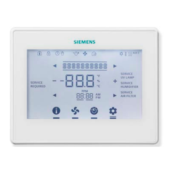
RDY2000 Commercial
Room Thermostat
Figure 1. RDY2000 Thermostat.
Product Specifications
System Compatibility
Conventional
Up to 3 Heating/3 Cooling stages
Heat Pumps
Up to 4 Heating/2 Cooling stages
Electrical Characteristics
Power Supply
24 Vac +/-20%, Class 2, 4A max.
Power Usage
4 VA (maximum)
Output Relay
Pilot duty, 1A max. per output, 4A
Ratings
max total
Ambient Limitations
Operating
23°F to 122°F (-5°C to 50°C)
Temperature
Storage/Shipping
-13°F to 158°F (-25°C to 70°C)
Temperature
Relative Humidity
Up to 95% (non-condensing)
Enclosure
Rating
NEMA 1
NOTE: The RDY2000 is not battery-powered. It
requires 24 Vac power from the HVAC
equipment at terminals RH/RC and C.
Product Number
RDY2000
Caution Notations
CAUTION:
Item Number 129-905, Rev. EA
Para accede al documento en Español, escanee el código QR que se encuentra en la parte trasera del termostato.
Equipment damage or loss of
data may occur if you do not
follow the procedures as
specified.
Installation Instructions
Required Tools
•
No. 1 Phillips screwdriver
•
1/8" flat-blade screwdriver
•
Drill with 1/8" drill bit
Expected Installation Time
15 minutes
CAUTION:
The RDY2000 is an advanced controller
designed to be installed by professional
HVAC technicians. Installation by non-
qualified personnel may result in degraded
system efficiency, occupant discomfort, or
equipment damage.
Prerequisites
•
All work must be performed in accordance
with applicable codes and standards.
•
Use 18 gauge thermostat wire for equipment
connections.
•
22 gauge shielded cable is recommended
for remote sensor wiring. Do not exceed 150
feet.
•
To replace an existing thermostat, verify if
24 Vac is present between the RH/RC and
C terminals.
•
Turn off power to the HVAC equipment
before attempting to remove the existing
thermostat.
•
Record wiring connections to existing
thermostat terminals.
•
Remove the existing thermostat before
proceeding.
Installation
1.
Install the thermostat base plate.
a. Feed the existing wires through the opening
in the base plate.
b. Secure the base plate to the mounting
surface using supplied hardware.
Document No. 129-905
March 26, 2015
Page 1 of 18
Advertisement
Table of Contents

Related Manuals for Siemens RDY2000


Summary of Contents for Siemens RDY2000
-
Page 1: Installation Instructions
C terminals. Rating NEMA 1 • Turn off power to the HVAC equipment NOTE: The RDY2000 is not battery-powered. It before attempting to remove the existing requires 24 Vac power from the HVAC thermostat. equipment at terminals RH/RC and C. -
Page 2: Thermostat Setup
Enables Scheduler, Time/Date, and tabs at the top and rotating the thermostat Installer Set Up configuration. Also downward until it is securely seated on the base Settings enables access to service reminder plate. and fault messages. Page 2 of 18 Siemens Industry, Inc. - Page 3 Cool Mode cooling mode. The system is actively in Heat Mode heating mode. Each segment Heating/Cooling represents one stage of Stages heating or cooling. Auxiliary heating stage: Auxiliary AUX=Stage 1: Aux Heating 2=Stage 2 Siemens Industry, Inc. Page 3 of 18...
-
Page 4: Wiring Diagrams
Document No. 129-905 Installation Instructions March 26, 2015 Wiring Diagrams Figure 4. Wiring Schematic, Conventional System. Page 4 of 18 Siemens Industry, Inc. - Page 5 Document No. 129-905 Installation Instructions March 26, 2015 Figure 5. Wiring Schematic, Heat Pump. Figure 6. Wiring Schematic, Aux Output 3. Siemens Industry, Inc. Page 5 of 18...
-
Page 6: Setup Wizard
Use the left [] and right [] arrows to access the different setpoints, and the + and – icons to adjust the setpoints. Touch the center of the screen to exit Setpoint Programming. Page 6 of 18 Siemens Industry, Inc. -
Page 7: Maintenance
Touch the center of the Home screen to access the room temperature screen. Press the Settings icon [ ] once and LOCKED displays. ] for 5 Press and hold the Settings icon [ seconds; PASSWORD displays. Siemens Industry, Inc. Page 7 of 18... - Page 8 Y = Auto adjust for Daylight Savings Time Daylight Savings Time Daylight P112 DAYLT SAVE N = Does not auto adjust for Daylight adjustment is based on Savings Savings Time USA schedule. * Included in Set-up Wizard Page 8 of 18 Siemens Industry, Inc.
- Page 9 12 = 12-hour format P212 Clock Format CLOCK 24 = 24-hour format Number of seconds that backlight P213 Backlight LIGHT 0 to 99 seconds stays on after screen is touched. 0 = Always off. Siemens Industry, Inc. Page 9 of 18...
- Page 10 8 = Occupancy (DI) approved for use with the 9 = Fault RDY2000. Only appears if P309 = 1/2/3/4/5. Temperature 0 = Type 2 Thermistor P310 TMP IN 3 Input 3 Type 1 = 0-10V Siemens Industry, Inc. Page 10 of 18...
- Page 11 P320 Humidity IND HMDTY regardless of whether there No = Humidification/dehumidification Control is a need for heating or relays are only energized if cooling. heating or cooling relay is energized. Siemens Industry, Inc. Page 11 of 18...
- Page 12 5. The new Expert Level password can be used to and return the unit to the Home screen. enter the full Expert Level set-up menu where both the Expert Level and Installer Level passwords can now be set to new values. Siemens Industry, Inc. Page 12 of 18...
- Page 13 Heating will begin when temperature 1°F (0.5°C) to 1°F P511 Heating Deadband HT DEADBND falls below lower point of deadband and ceases 5°F (4.0°C) (0.5°C) when temperature rises above upper port of deadband. Siemens Industry, Inc. Page 13 of 18...
- Page 14 99:99 Auxiliary Sequences • Humidity Setpoint: User adjustable to desired The RDY2000 primary sequences are designed to level in humidification mode. control single and multi-stage heating/cooling systems to Sensors: Onboard humidity sensor or optional remote maintain a user-selected temperature setpoint.
- Page 15 This function requires a schedule to be Air Quality output relay will be de-energized and configured. the fan relay shall revert to normal operation. Siemens Industry, Inc. Page 15 of 18...
- Page 16 Wake Evng Night Setpoint Heat Setpoint Cool 6:00 11:00 1:00 10:00 8:00 11:00 1:00 10:00 8:00 11:00 1:00 10:00 Time NOTE: Parameter 107 = 3; Parameter 108 = 4; Parameter 109 = F Siemens Industry, Inc. Page 16 of 18...
-
Page 17: Federal Communications Commission Notice
--Consult the dealer or an experienced radio/TV technician for help. Modifications This device complies with Part 15 of the FCC rules and IC rules. Changes or modifications not expressly approved by Siemens Industry Inc. could void the user’s authority to operate the equipment. - Page 18 Stage Differential - Heating Conv. = 1°F (0.5°C); HP = 2°F (1°C) P509 Heating Minimum Off Time P510 Heating Minimum On Time 5 (10 if heat pump) P511 Heating Deadband 1°F (0.5°C) P911 Expert Password 99:99 Siemens Industry, Inc. Page 18 of 18...