Table of Contents
Advertisement
Driver Install Guide Specification
Driver Install Guide Specification
1.
Model Description
MODEL
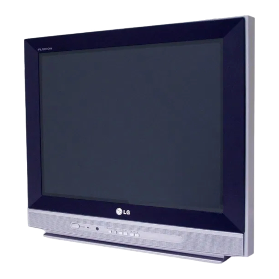
21FJ4AB-TH
SUFFIX
KDRLCEY
2.
Printing Specification
1. Trim Size (Format) :
2. Printing Colors
• Cover :
2 Colors (Black and Pantone 207C)
• Inside :
1 Color (Black)
3. Stock (Paper)
• Cover :
Uncoated paper 100 g/㎡
• Inside :
Uncoated paper 100 g/㎡
4. Printing Method :
5. Bindery :
6. Language :
7. Number of pages
• This part contain Eco-hazardous substances (Pb, Cd, Hg, Cr6+, PBB, PBDE, etc.)
within LG standard level, Details should be followed Eco-SCM management
standard[LG(56)-A-2524].
NOTE
• Especially, Part should be followed and controlled the following specification.
(1) Eco-hazardous substances test report should be submitted when Part certification
test and First Mass Production.
(2) Especially, Don't use or contain lead(Pb) and cadmium(Cd) in ink.
3.
Changes
10
9
8
7
6
5
4
3
2
1
REV.
SIGNATURE
MM/DD/YY
NO.
BRAND
Product Name
215mm x 280 mm
Saddle stitch
English
: 28
pages
CHANGE NO.
LG
SVC Manual
CHANGE
담 당
관 리 자
KIM S H
KANG K S
06.12.22
06.12.22
MFL31479115
Part No.
CONTENTS
Advertisement
Table of Contents

Related Manuals for LG 21FJ4AB/RB


Summary of Contents for LG 21FJ4AB/RB
- Page 1 7. Number of pages : 28 pages • This part contain Eco-hazardous substances (Pb, Cd, Hg, Cr6+, PBB, PBDE, etc.) within LG standard level, Details should be followed Eco-SCM management standard[LG(56)-A-2524]. NOTE • Especially, Part should be followed and controlled the following specification.
-
Page 2: Schematic Diagram
Pagination sheet P/NO . MFL31479115 Total pages : 28 pages Back Front Cover Front Back Cover Inside Inside Cover Cover 3854VA0196B-S1 (EN) (EN) Schematic diagram P/N : 3854VA0196B-S1 Fold 1 Fold 2 MAIN Fold 3 3854VA0196B-S1 2005.8.16 Fold 4 Punching spec unit : mm 7 x 5 COLOR TV... -
Page 3: Service Manual
COLOR TV SERVICE MANUAL CHASSIS : MC-059B MODEL: 21FJ4AB/RB MODEL: 21FJ4AB/RB-TH CAUTION BEFORE SERVICING THE CHASSIS, READ THE SAFETY PRECAUTIONS IN THIS MANUAL. -
Page 4: Table Of Contents
CONTENTS CONTENTS ....................2 SAFETY PRECAUTIONS................3 DESCRIPTION OF CONTROLS ..............4 SPECIFICATIONS ..................6 ADJUSTMENT ...................8 PRINTED CIRCUIT BOARD ..............13 TROUBLE SHOOTING ................14 BLOCK DIAGRAM ...................18 EXPLODED VIEW ..................20 EXPLODED VIEW PARTS LIST ..............21 REPLACEMENT PARTS LIST..............22 - 2 -... -
Page 5: Safety Precautions
SAFETY PRECAUTIONS IMPORTANT SAFETY NOTICE Many electrical and mechanical parts in this chassis have special safety-related characteristics. These parts are identified by in the Schematic Diagram and Replacement Parts List. It is essential that these special safety parts should be replaced with the same components as recommended in this manual to prevent X-RADIATION, Shock, Fire, or other Hazards. -
Page 6: Description Of Controls
DESCRIPTION OF CONTROLS All the functions can be controlled with the remote control handset. Some functions can also be adjusted with the buttons on the front panel of the set. Remote control handset Before you use the remote control handset, please install the bat- teries. - Page 7 10. MUTE switches the sound on or off. 11. TV/AV selects TV or AV mode. switches the set on from standby. 12. I/II/ (option) selects the language during dual language broadcast. (option) selects the sound output. 13. LIST POWER MUTE displays the programme table.
-
Page 8: Specifications
SPECIFICATIONS Note : Specification and others are subject to change without notice for improvement. Scope 4) Specification and performance of each parts are followed each drawing and specification by part number in This specification can be applied to all the television related to accordance with BOM. - Page 9 Front Local Key Power, Vol( ), PR( ), MENU, OK 7EA/ Front Turbo-Picture, Sound Option Remocon LG Code (NEC) Channel Auto prog. System/ Storage/ Normal/ Turbo Manual Storage/ System/ Channel/ Fine/ Search/ Name Prog. edit Copy/ Move/ Delete/ Skip Favorite...
-
Page 10: Adjustment
(When adhering DY, use the electric driver of which turning force is lower than 10Kg/Cm) <Fig. 2> 3-2. Adjustment Preparation 1) Input LG standard signal into 75Ω antenna terminal (or <Fig. 2> PAL-B/G 05CH) 2) Connect the digital multi-meter to terminal(with Hole/ 5-2. -
Page 11: White Balance Adjustment
(4) Dynamic Convergence (DYC) Adjustment (*In case there is excess RED color, adjust it using the VOLUME - key of the remote control until the RED color 1) Vertical Line Adjustment : Adjust by moving DY right and disappear.) left Color temperature : 12000°K 2) Horizontal Line Adjustment : Adjust by moving DY up X Coordinate : 270±8... - Page 12 8. SUB-BRIGHTNESS Adjustment 11. Instrument setting data Prior to this adjustment, the White balance adjustment (automatic adjustment) should be finished. <TABLE 2> VIDEO IC EEPROM Speed Delay 8-1. Adjustment Preparation SLave ADD 1) Receive the PAL B/G 5CH signal into RF mode regardless of channel.
- Page 13 <TABLE 1> Menu Adjustment Range Initial setting Remark VP 0 RF AGC RF AGC Delay 0 ~ 63 Necessary VP 1 H POS H PHASE 0 ~ 31 Necessary VP 2 V POS V Shift (V POSI) 0 ~ 15 Necessary VP 3 V SIZE...
- Page 14 Menu Adjustment Range Initial setting Remark 0 ~ 3 Unnecessary VP 54 Y TH Y TH VP 55 Y GAIN Y Gain 0 ~ 3 Unnecessary VP 56 R WIDTH R width 0 ~ 3 Unnecessary VP 57 R OFFSET R offset 0 ~ 3 Unnecessary...
-
Page 15: Printed Circuit Board
PRINTED CIRCUIT BOARD MAIN - 13 -... -
Page 16: Trouble Shooting
TROUBLE SHOOTING 1. TV FUNCTIONAL 2. TU / IF SECTION 3. VIDEO PROCESSING In case of influx NOISE - R/C is not operate Maneuver defectiveness Maneuver defectiveness Maneuver defectiveness - 14 -... - Page 17 4. SMPS PRIMARY SECTION 5. SMPS SECONDARY SECTION - 15 -...
- Page 18 6. VERTICAL SECTION 7. HORIZONTAL SECTION - 16 -...
- Page 19 8. SOUND PROCESSING SECTION 9. CPT DRIVE SECTION - 17 -...
-
Page 20: Block Diagram
BLOCK DIAGRAM - 18 -... - Page 21 MEMO - 19 -...
-
Page 22: Exploded View
EXPLODED VIEW Option - 20 -... -
Page 23: Exploded View Parts List
The components identified by mark critical for safety. EXPLODED VIEW PARTS LIST Replace only with part number specified. LOCA. NO PARTS No. DESCRIPTIONS 6334921001A CPT,Bare A51QDJ420X A0MLYG 21INCH FLAT 4/3 16KHZ 6334V21009B CPT,Bare A51QDJ420X(G) 21INCH FLAT 4/3 16KHZ 6335921011A CPT,ITC A51QDJ420X 21(0.2G) 21INCH FLAT +0.5G 4/3 16KHZ 6150Z-1228Y 6400VA0018G Speaker,Full Range JF SPK 5W/10W BARIUM 5W 8OHM 80DB 400HZ 71X41mM 6140VC2007E... -
Page 24: Replacement Parts List
REPLACEMENT PARTS LIST For Capacitor & Resistors, the CC, CX, CK, CN : Ceramic RD : Carbon Film charactors at 2nd and 3rd digit CQ : Polyestor RS : Metal Oxide Film in the P/No. means as follows; CE : Electrolytic RN : Metal Film RF : Fusible LOCA. - Page 25 For Capacitor & Resistors, CC, CX, CK, CN : Ceramic RD : Carbon Film the charactors at 2nd and 3rd CQ : Polyestor RS : Metal Oxide Film digit in the P/No. means as CE : Electrolytic RN : Metal Film follows;...
- Page 26 For Capacitor & Resistors, CC, CX, CK, CN : Ceramic RD : Carbon Film the charactors at 2nd and 3rd CQ : Polyestor RS : Metal Oxide Film digit in the P/No. means as CE : Electrolytic RN : Metal Film follows;...
- Page 27 For Capacitor & Resistors, CC, CX, CK, CN : Ceramic RD : Carbon Film the charactors at 2nd and 3rd CQ : Polyestor RS : Metal Oxide Film digit in the P/No. means as CE : Electrolytic RN : Metal Film follows;...
- Page 28 P/NO: 3854VA0196B - S1 2005.8.16...
- Page 29 SVC. SHEET : 3854VA0196B-S...
- Page 30 Dec., 2006 P/NO : MFL31479115 Printed in Korea...