Table of Contents
Advertisement
Advertisement
Table of Contents

Related Manuals for LG 21FS2CLX


Summary of Contents for LG 21FS2CLX
-
Page 1: Service Manual
COLOR TV SERVICE MANUAL CHASSIS : CW62B MODEL: 21FS2CLX/21FS2BLX MODEL: 21FS2CLX-ZV/21FS2BLX-ZV CAUTION BEFORE SERVICING THE CHASSIS, READ THE SAFETY PRECAUTIONS IN THIS MANUAL. Oct, 2006 P/NO : MFL31616408 b Printed in China... -
Page 2: Table Of Contents
CONTENTS Contents ....................2 Safety Precautions..................3 Control Descriptions ................4 Specifications....................7 Adjustment Instructions................8 SVC Remocon ..................13 Trouble Shooting ..................14 Printed circuit board................17 Block Diagram..................19 Exploded View..................19 Exploded View Parts List ...............21 Replacement Parts List ................22 SVC. Sheet....................- 2 -... -
Page 3: Safety Precautions
SAFETY PRECAUTIONS IMPORTANT SAFETY NOTICE Many electrical and mechanical parts in this chassis have special safety-related characteristics. These parts are identified by in the Schematic Diagram and Replacement Parts List. It is essential that these special safety parts should be replaced with the same components as recommended in this manual to prevent X-RADIATION, Shock, Fire, or other Hazards. -
Page 4: Control Descriptions
DESCRIPTION OF CONTROLS All the functions can be controlled with the remote control handset. Some functions can also be adjusted with the buttons on the front panel of the set. Remote control handset Before you use the remote control handset, please install the bat- teries. - Page 5 8. FAVOURITE selects a favorite programme. 9. EYE/ (option) switches the eye function on or off. 10. MUTE switches the sound on or off. 11. TV/AV selects TV or AV mode. switches the set on from standby. exits the Teletext mode (option) . 12.
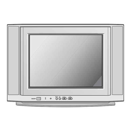
- Page 6 1. MAIN POWER (ON/OFF) switches the set on or off. 2. POWER/STANDBY INDICATOR illuminates brightly when the set is in standby 2 3 4 mode. dims when the set is switched on. 3. REMOTE CONTROL SENSOR Note : Only use the supplied remote control handset.
-
Page 7: Specifications
3 @ @ @ @ @ @ @ @ 5 h V 4 @ @ @ @ @ @ 0 Y h I 4 @ @ 0 M h e 1) performance : Follow the Standard of LG TV test parts,based upon P/N of B.O.M 2) Standards of Etc. requirement 5) Warm up TV set for more than 20min. -
Page 8: Adjustment Instructions
HEAT RUN adjusting DY. to the adjustment. (6) Signal: Received, the standard color signal.(65dB±1dB uV) Convergence Magnet 6Pole 4 Degaussing LG standard signal means the digital pattern (PAL_EU 05CH,NTSC_US 13CH). STC Pre-Adjustment ¢‚ 15 ~ 20mm PURITY Adjustment 3. Focus adjustment Let the screen Standard condition. -
Page 9: Screen Voltage Adjustment
(3) Widen two tabs of 4pole Magnet with equal angles and <Table 3> White Balance Initial Data accord red,blue vertical lines at the center of screen. 1. IC PARAMETER (4) With keeping angle of "c.clause",rotate tab and accord Name Maker Algorithm red/blue,green vertical lines at the center of screen. - Page 10 (3) VL (Vertical Linearity) (11) H ANGLE Adjust so that the boundary line between upper and lower Adjust the vertical slope half is in accord with geometric horizontal center of the (12) S CORRECT (S CORRECTION) CPT(PAL : E5ch., NTSC : US-13.). Adjust the receive Patter, keep the lattice's range (4) VA (Vertical Amplitude) same(Top/Center/Bottom)
- Page 11 9. SVC DEFAULT DATA [Table 7] SERVICE 4 (manage DATA by EEPROM MASTER) ITEM Description N-EU Refer WHITE STRETCH [Table 5] SERVICE 1 BLACK STRETCH CW62B BLACK STRATCH DEPTH ITEM DESCRIPTION N-EU DYNAMIC SKIN CONTROL VIDEO DEPENDENT CORING ACG take over PEAKING FREQUENCY DELAY Red Gain RATION POSITIVE/...
- Page 12 <Tabel 11> PSM MODE DATA SETTING (PAL) OPTION DATA BOM example ? W & ? h e ? ? W & @ @ ) X ? h ? W & @ L h e ? ? W & @ @ @ @ @ @ ) X ? g ? W &...
-
Page 13: Svc Remocon
SVC REMOCON - 13 -... -
Page 14: Trouble Shooting
TROUBLE SHOOTING 1. RF-STEREO MODEL 1) PICTURE OK / NO SOUND Selected correct system in menu Check the waveform IF 1 of TU101 Check/ Replace TU101 or Input signal Check the voltage at pin 3, 9, 16, 43, Check the waveform at pin 4, 5 of IC11 Check/ Replace IC11 86, 88, 90 of UOCIII Check the waveform at pin 4, 12 of... - Page 15 3) No Raster (2/2) Check the B + at D829 cathode Normal Abnormal OPEN Check Fuse of AC line Is the voltage each pin voltage of IC11 Check/ Replace Fuse Check the in/out of r e g u l a t o r ( I C 8 2 2 , Check pin 73 of Check the voltage of IC823, IC824)
- Page 16 4) No Picture/ No Sound Is any OSD displayed? Check IC11 pin 83, Check receiving system in MENU 84, 85 (R, G, B out) & execute Auto - Program Does the auto - Program operate properly Store on manual -program MENU Check the waveform Check IC11 pin 83, Check SMPS Trans...
-
Page 17: Printed Circuit Board
PRINTED CIRCUIT BOARD MAIN - 17 -... - Page 18 SIDE A/V - 18 -...
-
Page 19: Block Diagram
BLOCK DIAGRAM - 19 -... -
Page 20: Exploded View
EXPLODED VIEW - 20 -... -
Page 21: Exploded View Parts List
Cover Assembly 21FS2CG-TS MC059C 21” SY SET 3809900167H Cover Assembly 21FS2CLD-TV CW62B 21”SY LGESY-IR EBR33392703 PCB Assembly, Main MAIN M.I CW62B 21FS2CLX-ZV QUHLLCP EBR33392708 PCB Assembly, Main MAIN M.I CW62B 21FS2CLX-ZV QUZLLCP EBR33392713 PCB Assembly, Main MAIN M.I CW62B 21FS2CLX-ZV QDRLLBK EBR33932903 PCB Assembly, Main MAIN M.I CW62B 21FX5RLX-ZV KDRLLBK... -
Page 22: Replacement Parts List
REPLACEMENT PARTS LIST For Capacitor & Resistors, CC, CX, CK, CN : Ceramic RD : Carbon Film the characters at 2nd and 3rd CQ : Polyester RS : Metal Oxide Film digit in the P/No. means as CE : Electrolytic RN : Metal Film follows;... - Page 23 For Capacitor & Resistors, CC, CX, CK, CN : Ceramic RD : Carbon Film the characters at 2nd and 3rd CQ : Polyester RS : Metal Oxide Film digit in the P/No. means as CE : Electrolytic RN : Metal Film follows;...
- Page 24 For Capacitor & Resistors, CC, CX, CK, CN : Ceramic RD : Carbon Film the characters at 2nd and 3rd CQ : Polyester RS : Metal Oxide Film digit in the P/No. means as CE : Electrolytic RN : Metal Film follows;...
- Page 25 For Capacitor & Resistors, CC, CX, CK, CN : Ceramic RD : Carbon Film the characters at 2nd and 3rd CQ : Polyester RS : Metal Oxide Film digit in the P/No. means as CE : Electrolytic RN : Metal Film follows;...
- Page 26 For Capacitor & Resistors, CC, CX, CK, CN : Ceramic RD : Carbon Film the characters at 2nd and 3rd CQ : Polyester RS : Metal Oxide Film digit in the P/No. means as CE : Electrolytic RN : Metal Film follows;...
- Page 27 RD-96T1J4K70 4.7KOHM 5% 1/6W 3.2X1.8MM - MFL30441111 Manual EU MK/REG HU/BU/EN 30036801/2/3/4 R851 0RD8202F609 RD-96T1J82K0 82KOHM 5% 1/6W 3.2X1.8MM - MFL30441112 Manual USER CW62B LG EU PL 017B R852 0RD1003F609 RD-96T1J100K 100KOHM 5% 1/6W 3.2X1.8MM - MFL30441113 Manual USER CW62B LG EU RO R853 0RD1001F609 RD-96T1J1K00 1KOHM 5% 1/6W 3.2X1.8MM 5.0...
- Page 28 P/No : EBY31683801 2006.08.22...
-
Page 29: Svc. Sheet
SVC. SHEET : EBY31683801-S...