Table of Contents
Advertisement
SIMATIC HMI HMI device OP 73micro, TP 177micro (WinCC flexible)
SIMATIC HMI
HMI device
OP 73micro, TP 177micro
(WinCC flexible)
Operating Instructions
Order No. 6AV6691-1DF01-0AB0
09/2007
A5E01006740-02
Introduction
______________
Overview
Safety instructions and
______________
general notes
______________
Planning use
______________
Mounting and connection
Operator control components
______________
and LEDs
Configuring the operating
______________
system
Preparing and backing up a
______________
project
______________
Operating a project
______________
Operating alarms
______________
Maintenance and servicing
______________
Specifications
______________
Appendix
______________
Abbreviations
1
2
3
4
5
6
7
8
9
10
11
A
B
Advertisement
Table of Contents

Related Manuals for Siemens SIMATIC HMI OP 73micro


Summary of Contents for Siemens SIMATIC HMI OP 73micro
- Page 1 Introduction SIMATIC HMI HMI device OP 73micro, TP 177micro (WinCC flexible) ______________ Overview Safety instructions and ______________ general notes SIMATIC HMI ______________ Planning use HMI device OP 73micro, TP 177micro ______________ Mounting and connection (WinCC flexible) Operator control components ______________ and LEDs Operating Instructions Configuring the operating...
- Page 2 Trademarks All names identified by ® are registered trademarks of the Siemens AG. The remaining trademarks in this publication may be trademarks whose use by third parties for their own purposes could violate the rights of the owner.
-
Page 3: Introduction
Introduction Purpose of the operating instructions This operating instruction manual provides information based on the requirements defined by DIN 8418 for mechanical engineering documentation. This information relates to the device, its place of use, transport, storage, installation, use and maintenance. These operating instructions are intended for: ●... - Page 4 Introduction Position in the information landscape These operating instructions form part of the SIMATIC HMI documentation. The following information provides you with an overview of the SIMATIC HMI information landscape. User manuals ● WinCC flexible Micro: Describes basic principles of configuration using the WinCC flexible Micro Engineering System.
- Page 5 Online availability Technical documentation on SIMATIC products and SIMATIC systems is available in PDF format in various languages at the following addresses: ● SIMATIC Guide Technische Dokumentation in Deutsch: "http://www.ad.siemens.de/simatic/portal/html_00/techdoku.htm" ● SIMATIC Guide for Technical Documentation in English: "http://www.ad.siemens.de/simatic/portal/html_76/techdoku.htm" Conventions Configuration and runtime software differ with regard to their names as follows: ●...
- Page 6 Introduction Registered trademarks Names labeled with a ® symbol are registered trademarks of the Siemens AG. Other names used in this documentation may be trademarks, the use of which by third parties for their own purposes could violate the rights of the owner.
-
Page 7: Table Of Contents
Table of contents Introduction..............................3 Overview..............................11 Product overview .........................11 Design of the OP 73micro HMI device..................12 Design of the TP 177micro HMI device ..................13 Accessories..........................13 Miscellaneous ..........................14 Range of HMI software functions....................14 Communication with PLCs......................16 Safety instructions and general notes ...................... 17 Safety instructions........................17 Standards, Certificates and Approvals ..................18 Notes about usage........................20... - Page 8 Table of contents Mounting and connecting the TP 177micro ................48 4.3.1 Mounting the HMI device ......................48 4.3.2 Connecting the HMI device ......................49 4.3.2.1 Interfaces ............................ 50 4.3.2.2 Connecting the equipotential bonding circuit ................50 4.3.2.3 Connecting the PLC ........................53 4.3.2.4 Connecting the configuration computer ..................
- Page 9 Table of contents 7.1.3 Data Transfer Options........................92 Transfer............................92 7.2.1 Overview ............................92 7.2.2 Starting transfer..........................93 7.2.3 Testing a project ..........................94 Backup and restore........................95 7.3.1 Overview of backup and restoring ....................95 7.3.2 Resetting to Factory Settings for Backup and Restore..............96 7.3.3 Backup and Restore via WinCC flexible ..................96 7.3.4 Backup and Restore via ProSave ....................98 Updating the operating system ....................100...
- Page 10 Table of contents Maintenance and servicing ........................137 10.1 Maintenance and service ......................137 10.1.1 Cleaning screen ........................138 10.1.2 Protective membrane ........................ 138 10.2 Servicing and spare parts ......................139 Specifications ............................141 11.1 Dimensional drawings ....................... 141 11.1.1 Dimensional drawings, OP 73micro..................
-
Page 11: Overview
Overview Product overview Micro Panels OP 73micro and TP 177micro – particularly suitable for SIMATIC S7-200 Our new Micro Panels are tailored to applications with SIMATIC S7-200 Micro PLC and provide operating and monitoring functions for small-scale machines and plants. Short configuration and commissioning times, and their configuration in WinCC flexible form highlights of these panels. -
Page 12: Design Of The Op 73Micro Hmi Device
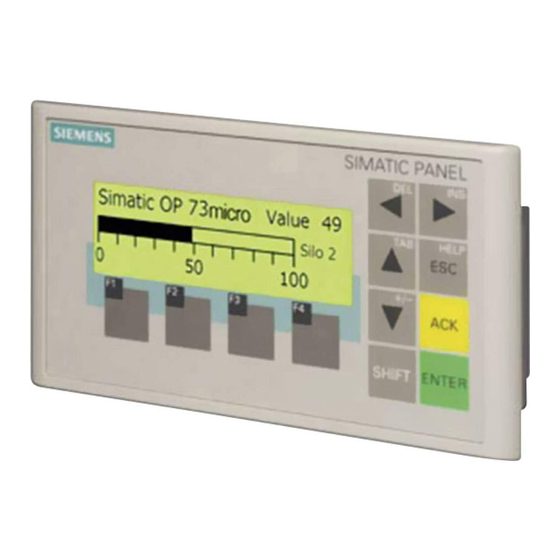
Overview 1.2 Design of the OP 73micro HMI device Design of the OP 73micro HMI device Views of the HMI device Figure 1-1 Front and side view ① Display ② Membrane keyboard ③ Clamping recess ④ Mounting seal Figure 1-2 Bottom view OP 73micro, TP 177micro (WinCC flexible) Operating Instructions, 09/2007, 6AV6691-1DF01-0AB0... -
Page 13: Design Of The Tp 177Micro Hmi Device
Overview 1.3 Design of the TP 177micro HMI device Design of the TP 177micro HMI device Views of the HMI device Figure 1-3 Front view and side view ① Construction-related opening – not a slot for a memory card ② Mounting seal ③... -
Page 14: Miscellaneous
PC-PPI adapter For the conversion from RS 232 to RS 485, order the PC-PPI adapter, Order No. 6ES7 901- 3CB30-0XA0, from Siemens AG. You need the PC-PPI adapter, for example, to update the operating system or to transfer project data. - Page 15 Overview 1.6 Range of HMI software functions Tags, values and lists Table 1-2 Range of functions for tags, values and lists Object Specification OP 73micro TP 177micro Tags Number Limit-value monitoring Input Input/Output Linear Scaling Input/Output Text lists Number Screens Table 1-3 Range of functions for screens Object...
-
Page 16: Communication With Plcs
Interconnection OP 73micro TP 177micro Number for MPI/PROFIBUS DP Siemens PLCs The following table shows the Siemens PLCs and protocols or profiles that can be used. Protocol / profile OP 73micro TP 177micro S7-200 If you require a baud rate of 9.6 Kbps, use the "DP" profile in WinCC flexible. -
Page 17: Safety Instructions And General Notes
Safety instructions and general notes Safety instructions Working on the cabinet WARNING Open equipment The HMI device is an open equipment. This means that the HMI device may only be installed in cubicles or cabinets, whereby the device can be operated from the front panel. Access to the cubicle or cabinet in which the HMI device is installed should only be possible by means of a key or tool and for personnel who have received instruction or are authorized. -
Page 18: Standards, Certificates And Approvals
● 94/9/EG "Equipment and protective systems intended for use in potentially explosive atmospheres" (ATEX). EC declaration of conformity The EC declarations of conformity are kept available for the responsible authorities at the following address: Siemens Aktiengesellschaft Automation & Drives A&D AS RD ST PLC PO Box 1963 D-92209 Amberg UL certification Underwriters Laboratories Inc. - Page 19 Safety instructions and general notes 2.2 Standards, Certificates and Approvals Underwriters Laboratories Inc. conforming to ● UL 508 (Industrial Control Equipment) ● CSA C22.2 No. 142, (Process Control Equipment) ● UL 1604 (Hazardous Location) ● CSA-213 (Hazardous Location) Approved for use in ●...
-
Page 20: Notes About Usage
Safety instructions and general notes 2.3 Notes about usage IEC 61131 The HMI device fulfills the requirements and criteria conforming to IEC 61131-2, Programmable Logic PLCs, Part 2: Operating resource requirements and tests. Notes about usage Use in industry The HMI device is designed for industrial use. The following standards are met: ●... - Page 21 Safety instructions and general notes 2.3 Notes about usage Potentially explosive atmosphere, Zone 2 Potentially explosive atmospheres are organized by zones. The zones are classified according to the probability of the presence of an explosive atmosphere. Zone Risk of explosion Example Infrequent and brief development Areas around flanged pipe joints with flat...
- Page 22 Maintenance Defective HMI devices must be returned to the manufacturer for repair. Repair may only be carried out by the manufacturer at his site. Location of the manufacturer: Siemens AG Automation & Drives Werner-von-Siemens-Straße 50 92224 Amberg Germany...
-
Page 23: Electromagnetic Compatibility
Safety instructions and general notes 2.4 Electromagnetic compatibility Electromagnetic compatibility Introduction The HMI device fulfills requirements of the EMC Directive of the domestic European market and other requirements. EMC-compliant installation of HMI devices An EMC-compliant installation of the HMI device and the use of interference-proof cables form the basis of trouble-free operation. - Page 24 Safety instructions and general notes 2.4 Electromagnetic compatibility Sinusoidal interference The table below shows the EMC properties of the modules with respect to sinusoidal interference. A requirement for this is that the HMI device meets the specifications and directives regarding electrical installation. Table 2-2 Sinusoidal interference Sinusoidal interference Test values...
-
Page 25: Transport And Storage Conditions
Safety instructions and general notes 2.5 Transport and storage conditions Transport and storage conditions Mechanical and climatic transport and storage conditions The transport and storage conditions of this HMI device exceed requirements conforming to IEC 61131-2. The following specifications apply to the transport and storage of an HMI device in its original packing. - Page 26 Safety instructions and general notes 2.5 Transport and storage conditions OP 73micro, TP 177micro (WinCC flexible) Operating Instructions, 09/2007, 6AV6691-1DF01-0AB0...
-
Page 27: Planning Use
Planning use Mounting information Mechanical and climatic conditions of use The HMI device is intended for installation in weatherproof permanent locations. The conditions of use are compliant with requirements to DIN IEC 60721-3-3: ● Class 3M3 (mechanical requirements) ● Class 3K3 (climatic requirements) Use with additional measures Examples of applications where the use of the HMI device requires additional measures: ●... - Page 28 Planning use 3.1 Mounting information Reduction of vibration If the HMI device is subjected to greater shocks or vibrations, you must take appropriate measures to reduce acceleration or amplitudes. We recommend fitting the HMI device to vibration-absorbent material (on metal shock absorbers, for example).
- Page 29 Planning use 3.1 Mounting information Climatic ambient conditions The HMI device may be used under the following climatic ambient conditions: Table 3-3 Climatic ambient conditions Ambient conditions Permissible range Remarks Temperature See the "Mounting positions and type of fixation" section Vertical mounting •...
-
Page 30: Mounting The Op 73Micro
Planning use 3.2 Mounting the OP 73micro Mounting the OP 73micro 3.2.1 Mounting positions and fixation Mounting position The HMI device is designed for mounting in racks, switch cabinets, switchboards and consoles. In the following, all of these mounting options are referred to by the general term "cabinet."... -
Page 31: Preparing For Mounting
Planning use 3.2 Mounting the OP 73micro Type of fixation Spring clamps are provided for mounting the device. Hook the clamps into the recesses of the HMI device. The overall HMI device dimensions are not exceeded by this. Figure 3-2 View of a mounting clamp ①... - Page 32 Planning use 3.2 Mounting the OP 73micro Maintaining clearances The HMI device must be installed with sufficient clearance: Figure 3-4 Clearance around the OP 73micro At least 10 mm clearance is required at the rear. NOTICE Ensure that the maximum ambient temperature is not exceeded when mounting the device in a cabinet and especially in a closed enclosure.
-
Page 33: Mounting The Tp 177Micro
Planning use 3.3 Mounting the TP 177micro Mounting the TP 177micro 3.3.1 Mounting positions and fixation Mounting position The HMI device is designed for mounting in racks, cabinets, control boards and consoles. In the following, all of these mounting options are referred to by the general term "cabinet." The HMI device is self-ventilated and approved for vertical and inclined mounting in stationary cabinets. - Page 34 Planning use 3.3 Mounting the TP 177micro Horizontal mounting When mounted horizontally, the cable inlets are located at the bottom. Vertical mounting When mounted vertically, the cable inlets are on the right. Type of fixation Spring clamps are provided for mounting the device. Hook the clamps into the recesses of the HMI device.
-
Page 35: Preparing For Mounting
Planning use 3.3 Mounting the TP 177micro 3.3.2 Preparing for mounting Select the HMI device mounting location What to observe when selecting the mounting location: ● Position the HMI device so that it is not subjected to direct sunlight. ● Position the HMI device to provide an ergonomic position for the operator and select a suitable mounting height. - Page 36 Planning use 3.3 Mounting the TP 177micro Maintaining clearances The following clearance is required around the HMI device in order to its ensure self- ventilation: Figure 3-8 Clearance around the HMI device At least 10 mm clearance is required at the rear. NOTICE Ensure that the maximum ambient temperature is not exceeded when mounting the device in a cabinet and especially in a closed enclosure.
-
Page 37: Information On Insulation Tests, Protection Class And Degree Of Protection
Planning use 3.4 Information on insulation tests, protection class and degree of protection Information on insulation tests, protection class and degree of protection Test voltages Insulation strength is demonstrated in the type test with the following test voltages conforming to IEC 61131-2: Table 3-4 Test voltages Circuits with a nominal voltage of U... -
Page 38: Nominal Voltages
Planning use 3.5 Nominal voltages Nominal voltages The following table shows the permitted nominal voltage and the corresponding tolerance range. Table 3-5 Permitted nominal voltages Nominal voltage Tolerance range +24 V DC 20.4 V to 28.8 V (–15%, +20%) OP 73micro, TP 177micro (WinCC flexible) Operating Instructions, 09/2007, 6AV6691-1DF01-0AB0... -
Page 39: Mounting And Connection
Check the package contents for visible signs of transport damage and for completeness. NOTICE Do not install parts damaged during shipment. In the case of damaged parts, contact your Siemens representative. Keep the supplied documentation in a safe place. The documentation belongs to the HMI device and is required for subsequent commissioning. -
Page 40: Connecting The Hmi Device
Mounting and connection 4.2 Mounting and connecting the OP 73micro Proceed as follows: 1. Check that the mounting seal is fitted on the HMI device. Do not install the mounting seal turned inside out. This may cause leaks in the mounting cut-out. -
Page 41: Interfaces
Mounting and connection 4.2 Mounting and connecting the OP 73micro NOTICE Connection sequence Always follow the correct sequence for connecting the HMI device. Failure to do so may result in damage to the HMI device. Connecting the cables When connecting the cables, ensure that you do not bend any of the contact pins. Secure the connectors with screws. -
Page 42: Connecting The Equipotential Bonding Circuit
Mounting and connection 4.2 Mounting and connecting the OP 73micro 4.2.2.2 Connecting the equipotential bonding circuit Potential differences Differences in potential between spatially separated system parts can lead to high equalizing currents over the data cables and therefore to the destruction of their interfaces. This situation may arise if the cable shielding is terminated at both ends and grounded at different system parts. - Page 43 Mounting and connection 4.2 Mounting and connecting the OP 73micro Wiring diagram Figure 4-3 Installing the equipotential circuit ① Chassis ground terminal on the HMI device (example) ② Equipotential bonding conductor cross-section: 4 mm ③ Cabinet ④ Equipotential bonding conductor cross-section: min. 16 mm ⑤...
-
Page 44: Connecting The Plc
Mounting and connection 4.2 Mounting and connecting the OP 73micro 4.2.2.3 Connecting the PLC Wiring diagram The following diagram illustrates the connection between the HMI device and PLC. S7-200 Figure 4-4 Connection to the PLC The interfaces are described in the Specifications section. Note when connecting NOTICE Always use the approved cables to connect a SIMATIC S7 PLC. - Page 45 Mounting and connection 4.2 Mounting and connecting the OP 73micro See also Interfaces (Page 41) Wiring diagram The figure below illustrates the connection between the power supply and the HMI device. Figure 4-6 Connecting the power supply The interfaces are described in the Specifications section. Note when connecting The power terminal block is included in the assembly kit and is designed for conductors with a maximum cross-section of 1.5 mm...
-
Page 46: Switching On Power And Testing The Hmi Device
Mounting and connection 4.2 Mounting and connecting the OP 73micro Polarity reversal protection The HMI device is equipped with a polarity reversal protection circuit. Connecting the power supply CAUTION Ensure safe electrical insulation of the power supply. Always use power supply modules that conform to IEC 364-4-41 or HD 384.04.41 (VDE 0100, Part 410). - Page 47 Mounting and connection 4.2 Mounting and connecting the OP 73micro The HMI device automatically sets transfer mode during initial startup if it does no contain any project data yet. The following dialog appears: Transfer Connecting to host. Figure 4-10 "Transfer" dialog HELP 3.
-
Page 48: Mounting And Connecting The Tp 177Micro
Mounting and connection 4.3 Mounting and connecting the TP 177micro Mounting and connecting the TP 177micro 4.3.1 Mounting the HMI device Requirements Four mounting clamps from the kit are needed to mount the the HMI device. The mounting seal must be available on the HMI device. If the mounting seal is damaged, order a replacement seal. -
Page 49: Connecting The Hmi Device
Mounting and connection 4.3 Mounting and connecting the TP 177micro NOTICE Check the fit of the mounting seal on the front. The mounting seal must not protrude from the HMI device. Otherwise, repeat steps 1 to 4. 4.3.2 Connecting the HMI device Requirements The HMI device must be mounted according to the specifications of these operating instructions. -
Page 50: Interfaces
Mounting and connection 4.3 Mounting and connecting the TP 177micro 4.3.2.1 Interfaces The figure below shows the interfaces of the HMI device. Figure 4-12 Interfaces of the HMI device ① Chassis ground terminal ② Power supply connector ③ RS 485 interface (IF 1B) See also Power supply (Page 146) RS 485 (IF 1B) on TP 177micro (Page 147) - Page 51 Mounting and connection 4.3 Mounting and connecting the TP 177micro General requirements of equipotential bonding Potential differences must be reduced by means of equipotential bonding in order to ensure trouble-free operation of the relevant components of the electronic system. The following must therefore be observed when installing the equipotential bonding circuit: ●...
-
Page 52: Wiring Diagram
Mounting and connection 4.3 Mounting and connecting the TP 177micro Wiring diagram Figure 4-13 Installing the equipotential circuit ① Chassis ground terminal on the HMI device (example) ② Equipotential bonding conductor cross-section: 4 mm ③ Cabinet ④ Equipotential bonding conductor cross-section: min. 16 mm ⑤... -
Page 53: Connecting The Plc
Mounting and connection 4.3 Mounting and connecting the TP 177micro 4.3.2.3 Connecting the PLC Wiring diagram The following diagram illustrates the connection between the HMI device and PLC. S7-200 RS 485 Figure 4-14 Connecting the PLC The interfaces are described in the Specifications section. Note when connecting NOTICE Always use the approved cables to connect a SIMATIC S7 PLC. - Page 54 Mounting and connection 4.3 Mounting and connecting the TP 177micro See also Interfaces (Page 50) Wiring diagram The figure below illustrates the connection between the power supply and the HMI device. Figure 4-16 Connecting the power supply Note when connecting The power terminal block is included in the assembly kit and is designed for conductors with a maximum cross-section of 1.5 mm Connecting the terminal block...
-
Page 55: Switching On Power And Testing The Hmi Device
Mounting and connection 4.3 Mounting and connecting the TP 177micro Connecting the power supply CAUTION Ensure safe electrical insulation of the power supply. Always use power supply modules that conform to IEC 364-4-41 or HD 384.04.41 (VDE 0100, Part 410). Always use power supply modules that comply to SELV (Safety Extra-Low Voltage) and PELV (Protective Extra Low Voltage) standards. - Page 56 Mounting and connection 4.3 Mounting and connecting the TP 177micro The HMI device automatically switches to "Transfer" mode during initial startup if no project is already loaded on the device. The following dialog appears: Figure 4-19 "Transfer" dialog 3. Touch "Cancel" to stop the transfer. Result The Loader appears again.
-
Page 57: Communication With S7-200
Mounting and connection 4.4 Communication with S7-200 Communication with S7-200 Introduction This section is intended for configuration engineers of the HMI device. The following chapter contains information necessary for configuring: ● Connection options to the PLC ● Communication using WinCC flexible 4.4.1 Topologies Introduction... -
Page 58: Communication In The Network
Mounting and connection 4.4 Communication with S7-200 4.4.1.2 Communication in the network Introduction A network consists of several nodes which are connected to the same bus cable and communicate with each other. All nodes are assigned a unique network address. Which devices communicate with each other is defined when the devices are configured. - Page 59 Mounting and connection 4.4 Communication with S7-200 Several HMI devices on one S7-200 An S7-200 PLC supports the connection of up to three HMI devices per CPU interface. The DP interface of a CPU215-2DP supports the connection of up to five HMI devices. Configuration example: Figure 4-22 Three HMI devices on one S7-200...
-
Page 60: Configuration Instructions
Mounting and connection 4.4 Communication with S7-200 4.4.1.3 Configuration instructions Please observe the following configuration instructions: Note For a first-generation SIMATIC S7-200 (CPU 214, 215, 216), use the connection at Port 1 for communication via MPI/PROFIBUS DP. When using a CPU 214, set a baud rate of 9.6 Kbps. -
Page 61: Configuring Protocol Parameters
Mounting and connection 4.4 Communication with S7-200 4.4.2.1 Configuring protocol parameters Parameters to be set To set the parameters, double-click "Communication ▶ Connections" in the WinCC flexible project screen of the HMI device. From the "Communications driver" column of the working area, select the value "SIMATIC S7-200."... - Page 62 Mounting and connection 4.4 Communication with S7-200 ● "Baudrate" Set the data baud rate for the network here. The baud rate is determined by the slowest HMI device connected to the network. Possible baud rates for the HMI devices OP 73micro and TP 177micro: –...
-
Page 63: User Data Areas
Mounting and connection 4.4 Communication with S7-200 4.4.3 User data areas 4.4.3.1 Communication between HMI device and controller Communication principle The HMI device and the S7–200 controller communicate using ● tags and ● user data areas Tags The controller and the HMI device exchange data using process values. During configuration, tags are created pointing to addresses in the PLC. -
Page 64: Time Synchronization Via Area Pointer
Mounting and connection 4.4 Communication with S7-200 4.4.3.3 Time synchronization via area pointer Introduction When the "Date/Time PLC" area pointer is configured, the HMI device reads the date and time cyclically from the PLC. The position of the "Date/Time PLC" user data area is defined in the area pointer. - Page 65 Mounting and connection 4.4 Communication with S7-200 ● Comment This is where you can save a comment which describes the use of the area pointer, for example. Function The PLC describes the data area of the "Date/Time PLC" area pointer. All specifications are coded in BCD format.
-
Page 66: Mechanism Of Error Alarm Acknowledgment
Mounting and connection 4.4 Communication with S7-200 4.4.3.4 Mechanism of error alarm acknowledgment Introduction Alarms indicate the process and plant states on the HMI device. Alarms are configured in WinCC flexible. Each alarm is assigned an alarm bit in the PLC. Each alarm bit must be a tag or tag element which is configured in WinCC flexible. - Page 67 Mounting and connection 4.4 Communication with S7-200 Acknowledgment on the HMI device The PLC can only detect an error alarm acknowledgment at the HMI device if the "Read acknowledgment tag" bit is configured. The HMI device sets the "Read acknowledgment tag" bit in the PLC after it has acknowledged an alarm.
- Page 68 Mounting and connection 4.4 Communication with S7-200 OP 73micro, TP 177micro (WinCC flexible) Operating Instructions, 09/2007, 6AV6691-1DF01-0AB0...
-
Page 69: Operator Control Components And Leds
Operator control components and LEDs Front side operator control components and indicators on the OP 73micro Figure 5-1 Operator control components and LEDs ① Soft keys ② System keys – control keys Standard input device at the HMI device is the keyboard. This is basically composed of two key groups: ●... -
Page 70: Front Side Operator Control Components And Leds On The Tp 177Micro
Operator control components and LEDs 5.2 Front side operator control components and LEDs on the TP 177micro See also Design of the OP 73micro HMI device (Page 12) Front side operator control components and LEDs on the TP 177micro Figure 5-2 Operator control components ①... -
Page 71: Configuring The Operating System
Configuring the operating system Configuring the operating system for the OP 73micro 6.1.1 Overview Loader The figure below shows the Loader. It appears briefly when the HMI device starts up. Loader Transfer Start Info/Settings Figure 6-1 Loader The Loader menu commands have the following functions: ●... -
Page 72: Info/Settings" Menu
Configuring the operating system 6.1 Configuring the operating system for the OP 73micro Editing dialog entries Button Action Selects the previous or next list entry. +/– The selected list entry is accepted. ENTER HELP You can undo your input as long you have not yet confirmed the selected list entry with ENTER See also... - Page 73 Configuring the operating system 6.1 Configuring the operating system for the OP 73micro Password protection You can protect the "Logon/Settings" menu from unauthorized access by assigning a password. This prevents inadvertent wrong operation and increases security for the plant or machine security because access to the settings is denied.
-
Page 74: Setting Screen Contrast
Configuring the operating system 6.1 Configuring the operating system for the OP 73micro 6.1.2.2 Setting screen contrast Requirements "Info/Settings ▶ Contrast" was selected from the Loader menu. Principle Contrast Press Up/Down to change contrast. Figure 6-4 "Contrast" dialog This dialog is used to adjust the contrast and therefore indirectly controls screen brightness. NOTICE Screen contrast The screen contrast can be increased and reduced within a wide range. -
Page 75: Viewing Information About The Version Of The Hmi Device Image
Configuring the operating system 6.1 Configuring the operating system for the OP 73micro 6.1.2.4 Viewing information about the version of the HMI device image Requirements "Info/Settings ▶ Version Info" was selected from the Loader menu. Principle Version Info 01.00.00.00_05.08 BL 0.17/2004-xx-xx Figure 6-6 "Version Info"... -
Page 76: Setting The Delay
Configuring the operating system 6.1 Configuring the operating system for the OP 73micro Procedure Proceed as follows: 1. Close the project. 2. Open the "Logon/Settings" menu. 3. Edit the settings. 4. Close the "Logon/Settings" menu. 6.1.3.2 Setting the delay Requirements "Info/Settings ▶... -
Page 77: Assigning, Editing And Deleting Passwords
Configuring the operating system 6.1 Configuring the operating system for the OP 73micro 6.1.3.4 Assigning, editing and deleting passwords Introduction To restrict access to the "Settings" menu to specific members of staff, define a password in the "Password" dialog. Requirements ●... - Page 78 Configuring the operating system 6.1 Configuring the operating system for the OP 73micro Result ● The "Settings" menu opens. ● The "Settings" menu is password protected. Procedure – Deleting a password Proceed as follows: ENTER 1. Press – do not enter any other characters. The "Confirmation"...
-
Page 79: Configure The Data Channel
Configuring the operating system 6.1 Configuring the operating system for the OP 73micro 6.1.3.5 Configure the data channel Introduction By disabling a data channel, you can protect the HMI device from unintentional overwriting of project data and of the HMI device image. Requirements "Info/Settings ▶... -
Page 80: Configuring The Operating System For The Tp 177Micro
Configuring the operating system 6.2 Configuring the operating system for the TP 177micro Configuring the operating system for the TP 177micro 6.2.1 Overview Loader The figure below shows the Loader. It appears briefly when the HMI device starts up. Figure 6-14 HMI device Loader The Loader buttons have the following functions: ●... -
Page 81: Control Panel
Configuring the operating system 6.2 Configuring the operating system for the TP 177micro See also Switching on power and testing the HMI device (Page 55) 6.2.2 Control Panel 6.2.2.1 Overview Control Panel of the HMI device The HMI device Control Panel can be used to modify the following HMI device settings: ●... -
Page 82: Changing Screen Settings
Configuring the operating system 6.2 Configuring the operating system for the TP 177micro General Procedure Proceed as follows to change settings in the Control Panel: 1. You must exit the project before changing settings in the Control Panel. Use the relevant operator control object provided in the project. - Page 83 Configuring the operating system 6.2 Configuring the operating system for the TP 177micro 2. The "Contrast" group contains the "UP" and "DOWN" buttons. To adjust the screen contrast: – Touch the "UP" button to increase screen contrast. – Touch the "DOWN" button to reduce screen contrast. 3.
-
Page 84: Displaying Information About The Hmi Device
Configuring the operating system 6.2 Configuring the operating system for the TP 177micro 6.2.2.3 Displaying information about the HMI device Requirements You have touched the "OP" icon on the Control Panel. Procedure Proceed as follows: 1. Open the "OP Properties" dialog and select the "Device" tab. Figure 6-17 "OP Properties"... -
Page 85: Calibrating The Touch Screen
Configuring the operating system 6.2 Configuring the operating system for the TP 177micro 6.2.2.4 Calibrating the touch screen Introduction Depending on the mounting position and viewing angle, it is possible that parallax may occur when operating the HMI device. In order to prevent any operating errors as a result, calibrate the screen again in the startup phase or during runtime. -
Page 86: Changing The Password Setting For The Control Panel
Configuring the operating system 6.2 Configuring the operating system for the TP 177micro 6.2.2.5 Changing the password setting for the Control Panel Requirements "Password" icon in the Control Panel has been touched. The "Password Properties" dialog is shown. Figure 6-19 "Password Properties"... -
Page 87: Setting The Screen Saver
Configuring the operating system 6.2 Configuring the operating system for the TP 177micro Procedure – Deleting a password Proceed as follows: 1. Delete the entries for "Password" and "Confirm Password". 2. Close the dialog with Result Password protection for the Control Panel menu is revoked. See also Overview (Page 80) 6.2.2.6... -
Page 88: Configure The Data Channel
Configuring the operating system 6.2 Configuring the operating system for the TP 177micro NOTICE Activating the Screen Saver You should always activate the screen saver. Otherwise, the screen contents may leave a burn-in effect in the background if they appear too long. This effect is reversible, however. -
Page 89: Preparing And Backing Up A Project
Preparing and backing up a project Overview Configuration and process management phases HMI devices can be used to operate and monitor tasks in process and production automation. The plant screens on the HMI devices are used to provide a clearer overview of active processes. -
Page 90: Setting The Operating Mode
Preparing and backing up a project 7.1 Overview Transferring the project to the HMI device The following can be performed to transfer a project to an HMI device: ● Transfer the project from the configuration computer ● Restore the project from a PC using ProSave In this case, an archived project is transferred from a PC to the HMI device. -
Page 91: Reusing Existing Projects
Preparing and backing up a project 7.1 Overview "Transfer" mode In this mode, you can transfer a project from the configuration computer to the HMI device or backup and restore HMI device data, for example. The following options are available for setting "Transfer" mode on the HMI device: ●... -
Page 92: Data Transfer Options
Preparing and backing up a project 7.2 Transfer 7.1.3 Data Transfer Options Overview The following table shows the options for transferring data between the configuration computer and OP 73micro or TP 177micro. Type Type OP 73micro TP 177micro Backup Serial (with reset to factory setting) Serial Restore Serial (with reset to factory setting) -
Page 93: Starting Transfer
Preparing and backing up a project 7.2 Transfer 7.2.2 Starting transfer Introduction You can set "Transfer" mode manually on the HMI device using a configured operator control object and during ongoing operation. Requirements ● The *.hmi project is opened in WinCC flexible. ●... -
Page 94: Testing A Project
Preparing and backing up a project 7.2 Transfer 7.2.3 Testing a project Introduction There are two options on the HMI device testing a project: ● Offline testing of the project Offline testing means that communication between the HMI device and PLC is down while the test is being carried out. -
Page 95: Backup And Restore
Preparing and backing up a project 7.3 Backup and restore Backup and restore 7.3.1 Overview of backup and restoring Introduction Data located on the HMI device can be backed up using a PC external to the HMI device and can be restored from it. The following data in the internal Flash memory can be backed up and restored: ●... -
Page 96: Resetting To Factory Settings For Backup And Restore
Preparing and backing up a project 7.3 Backup and restore 7.3.2 Resetting to Factory Settings for Backup and Restore Reset to factory setting In ProSave or WinCC flexible, you can perform a restore with or without resetting to factory settings. ●... - Page 97 Preparing and backing up a project 7.3 Backup and restore 5. In WinCC flexible, select the menu command "Project ▶ Transfer ▶ Backup". The "Backup Settings" dialog opens. 6. Select the data to be backed up. 7. Select a destination folder and a file name for the *.psb backup file. 8.
-
Page 98: Backup And Restore Via Prosave
Preparing and backing up a project 7.3 Backup and restore See also Configure the data channel (Page 88) Configure the data channel (Page 79) Setting the operating mode (Page 90) Overview of backup and restoring (Page 95) Data Transfer Options (Page 92) 7.3.4 Backup and Restore via ProSave Introduction... - Page 99 Preparing and backing up a project 7.3 Backup and restore Procedure - restore Proceed as follows: 1. When restoring with reset to factory setting only: Switch off power to the HMI device. 2. From the Windows Start menu, run ProSave on the PC. 3.
-
Page 100: Updating The Operating System
Preparing and backing up a project 7.4 Updating the operating system Updating the operating system 7.4.1 Overview Overview A compatibility conflict may occur when transferring a project to the HMI device. This is caused by different versions of the engineering software and the HMI device image. The configuration computer cancels the transfer and triggers an alarm to indicate a compatibility conflict. -
Page 101: Updating The Operating System Using Wincc Flexible
Preparing and backing up a project 7.4 Updating the operating system 7.4.2 Updating the operating system using WinCC flexible Requirements ● The HMI device is connected to a configuration computer. ● No project is open in WinCC flexible. Procedure Proceed as follows: 1. -
Page 102: Updating The Operating System In Prosave
Preparing and backing up a project 7.4 Updating the operating system 7.4.3 Updating the operating system in ProSave Requirements ● The HMI device is connected to a PC on which ProSave is installed. Procedure Proceed as follows: 1. Switch off power to the HMI device. 2. -
Page 103: Operating A Project
Operating a project Operating a project on OP 73micro 8.1.1 Overview Soft keys with global function assignment A soft key with global function assignment always triggers the same action on the HMI device or in the PLC, regardless of the current screen. An example of such an action is the activation of a screen. - Page 104 Operating a project 8.1 Operating a project on OP 73micro System keys The system keys (control keys) are used for operator input on the HMI device. Table 8-1 Overview of control keys Function Action Moving the cursor Activates the next field in horizontal direction Activates the next field in vertical direction +/–...
-
Page 105: Setting The Project Language
Operating a project 8.1 Operating a project on OP 73micro 8.1.2 Setting the project language Introduction The HMI device supports multilingual projects. You need to configure a corresponding operator control object which lets you change the language setting on the HMI device during runtime. - Page 106 Operating a project 8.1 Operating a project on OP 73micro Numerical values Enter the characters of numerical values using the system keyboard. Press to edit any ENTER character of the value with the help of the cursor keys. You can delete a value from the field by pressing SHIFT Formats for the visualization of numerical values You can enter values in numerical input fields based on the following formats:...
-
Page 107: Entering And Editing Numerical And Alphanumerical Values
Operating a project 8.1 Operating a project on OP 73micro 8.1.3.2 Entering and Editing Numerical and Alphanumerical Values Requirement An IO field has been enabled with or using the cursor keys. SHIFT Navigating in fields Table 8-3 Overview of control keys for navigating in fields Action The previous or following character is marked. - Page 108 Operating a project 8.1 Operating a project on OP 73micro Procedure – editing specific characters of a value Proceed as follows: ENTER 1. Press 2. Select the relevant character with +/– 3. Replace the character with 4. Press ENTER This confirms your entries. To cancel the entry, press Call sequence of the characters When you initially enter a value in an alphanumerical input field, the letter "A"...
- Page 109 Operating a project 8.1 Operating a project on OP 73micro Procedure – inserting characters ENTER 1. Press 2. Move the cursor to the required position. 3. Press to insert a space character. SHIFT The characters already entered move one position to the right from the cursor position. If the characters are right aligned: The characters already entered move one position to the left from the cursor position.
-
Page 110: Entering And Editing Symbolic Values
Operating a project 8.1 Operating a project on OP 73micro Example for alphanumerical input Activate the the input box. The following table shows the keys you need to press to enter "OP 73": Instruction Display Press 1 x to begin input ENTER Keep pressing until "O"... -
Page 111: Entering And Modifying Date And Time
Operating a project 8.1 Operating a project on OP 73micro Procedure Proceed as follows: ENTER 1. Enable the selection list with This enables the selection list which contains the configured symbolic entries. +/– 2. Select an entry with 3. Save or cancel the entry. 8.1.3.4 Entering and modifying date and time Requirements... -
Page 112: Viewing Infotext
Operating a project 8.1 Operating a project on OP 73micro 8.1.3.5 Viewing infotext Introduction The configuration engineer uses infotext to provide additional information and operating instructions with respect to screens and operable screen objects. An infotext may contain information on the value to be set in an IO field, for example. Enter temperature setpoint for Tank_1 (Range 40 to 80 °C) -
Page 113: Project Security
Operating a project 8.1 Operating a project on OP 73micro 8.1.4 Project security Overview Operation of a project can be protected by the configuration engineer by implementing a security system. If operator control objects protected by a password are operated, the HMI device requests the entry of a password. -
Page 114: Close The Project
Operating a project 8.1 Operating a project on OP 73micro Password The password and logoff timeout values are coded in a list and saved to non-volatile memory on the HMI device. Note Depending on the transfer settings, changes to the password list are overwritten when the project is transferred again. -
Page 115: Operating A Project On Tp 177Micro
Operating a project 8.2 Operating a project on TP 177micro Operating a project on TP 177micro 8.2.1 Overview Operating touch objects Touch objects represent touch-sensitive operator control objects on the HMI device screen such as buttons, IO fields and alarm windows. Touch objects are basically operated in the same way as conventional keys. -
Page 116: Setting The Project Language
Operating a project 8.2 Operating a project on TP 177micro The configuration engineer defines the appearance of a selected field, for example, its line width and color for the focus. ● Invisible buttons The focus for invisible buttons is not identified after selection by default. The configuration engineer may, however, configure invisible buttons so that their outline appears when touched. -
Page 117: Entries And Help Within A Project
Operating a project 8.2 Operating a project on TP 177micro 8.2.3 Entries and help within a project 8.2.3.1 Overview Procedure Values are entered in the project input fields. The values are transferred from the input fields to the PLC. Proceed as follows: 1. -
Page 118: Entering And Editing Numerical Values
Operating a project 8.2 Operating a project on TP 177micro Limit value test of numerical values Tags can be assigned limit values. The current limit values are indicated in the numerical screen keyboard. If an alarm window has been configured, a system alarm is automatically output to indicate any violation of the configured input value limits. - Page 119 Operating a project 8.2 Operating a project on TP 177micro Procedure You can enter numerical and hexadecimal values character by character using the numerical screen keyboard Proceed as follows: 1. Touch the relevant IO field on the screen. The numerical screen keyboard opens and displays the current value. 2.
-
Page 120: Entering And Editing Alphanumerical Values
Operating a project 8.2 Operating a project on TP 177micro 8.2.3.3 Entering and editing alphanumerical values Alphanumerical screen keyboard When you touch an IO field on the HMI device touch screen, the alphanumerical screen keyboard appears. The keyboard is automatically hidden again when input is complete. Figure 8-5 Alphanumerical screen keyboard, standard layer The layout of the screen keyboard for a vertically mounted HMI device differs slightly from... -
Page 121: Entering And Editing Symbolic Values
Operating a project 8.2 Operating a project on TP 177micro – Use the key to toggle between the Shift layer and standard layer of the keyboard. When you toggle the layer, the key labels on the screen keyboard change. – Select to view the infotext of the IO field. -
Page 122: Entering And Modifying Date And Time
Operating a project 8.2 Operating a project on TP 177micro Procedure Set symbolic values with the help of the symbolic screen keyboard. Proceed as follows: 1. Touch the relevant IO field on the screen. The symbolic screen keyboard opens and displays the current value. 2. -
Page 123: Viewing Infotext
Operating a project 8.2 Operating a project on TP 177micro 8.2.3.6 Viewing infotext Purpose The configuration engineer uses infotext to provide additional information and operating instructions with respect to screens and operable screen objects. Infotext can provide information on the value to be entered in an IO field, for example. Figure 8-7 Infotext for an IO field, example Infotext for input objects... -
Page 124: Project Security
Operating a project 8.2 Operating a project on TP 177micro 8.2.4 Project security Overview Operation of a project can be protected by the configuration engineer by implementing a security system. If operator control objects protected by a password are operated, the HMI device requests the entry of a password. -
Page 125: Close The Project
Operating a project 8.2 Operating a project on TP 177micro 8.2.5 Close the project. Procedure Proceed as follows: 1. Use the corresponding operator control object to close the project. Wait for the Loader to open after you closed the project. 2. -
Page 126: Operating The Trend View
Operating a project 8.2 Operating a project on TP 177micro Value Table The trend values can be read from the value table, if this is configured. Ruler The exact trend values can be read from the ruler, if this is configured. 8.2.6.2 Operating the Trend View Value Table... -
Page 127: Operating Alarms
Operating alarms Overview Alarms Alarms indicate events and states on the HMI device which have occurred in the system, in the process or on the HMI device itself. A status is reported when it is received. An alarm could trigger one of the following alarm events: ●... -
Page 128: Operating Alarms On The Op 73Micro
Operating alarms 9.2 Operating alarms on the OP 73micro Alarm classes Alarms are assigned to various alarm classes: ● Error Alarms in this class must always be acknowledged. Alarms normally indicate critical errors within the plant such as "Motor temperature too high". ●... - Page 129 Operating alarms 9.2 Operating alarms on the OP 73micro Operator control components Functions of the HMI device keys in the alarm view: Button Function Show an alarm infotext HELP SHIFT Edit alarm ENTER Acknowledge alarm Show the full text of the selected alarm in a separate window, the alarm text window.
- Page 130 Operating alarms 9.2 Operating alarms on the OP 73micro Viewing long alarm text The alarm text window can be used to view infotexts which can not be output in full length in the alarm view. 1. Select the alarm using the cursor keys. 2.
-
Page 131: Acknowledging An Alarm
Operating alarms 9.2 Operating alarms on the OP 73micro 9.2.2 Acknowledging an Alarm Requirements ● The alarm to be acknowledged is shown in the alarm window or in the alarm view. ● Either the alarm window or the alarm view is enabled. ●... -
Page 132: Operating Alarms On The Tp 177Micro
Operating alarms 9.3 Operating alarms on the TP 177micro Result The system executes the additional functions of the alarm. You may find additional information on this in your plant documentation. Note When you edit an unacknowledged alarm, it is acknowledged automatically. See also Displaying alarms (Page 128) Operating alarms on the TP 177micro... - Page 133 Operating alarms 9.3 Operating alarms on the TP 177micro Operator control components Functions of the alarm view buttons: Button Function Displays an alarm infotext Edits an alarm Acknowledges an alarm Displays the full text of the selected alarm in a separate window, the alarm text window If necessary, you can scroll in the alarm text window.
-
Page 134: Acknowledging An Alarm
Operating alarms 9.3 Operating alarms on the TP 177micro Alarm indicator The alarm indicator is a graphical symbol that shows current errors or errors which need to be acknowledged, depending on the configuration. Figure 9-3 Alarm indicator with three queued alarms The alarm indicator flashes as long as alarms are queued for acknowledgment. -
Page 135: Editing An Alarm
Operating alarms 9.3 Operating alarms on the TP 177micro 9.3.3 Editing an Alarm Introduction The configuration engineer can assign additional functions to each alarm. These functions are executed when the alarm is processed. Requirements ● The alarm to be edited is indicated in the alarm window or in the alarm view. ●... - Page 136 Operating alarms 9.3 Operating alarms on the TP 177micro OP 73micro, TP 177micro (WinCC flexible) Operating Instructions, 09/2007, 6AV6691-1DF01-0AB0...
-
Page 137: Maintenance And Servicing
Maintenance and servicing 10.1 Maintenance and service Scope of maintenance The HMI device is designed for maintenance-free operation. Despite this, the touch screen or keyboard membrane and the display must be cleaned regularly. Preparation CAUTION Faulty operation Always switch off the HMI device before cleaning it. This will ensure that you do not trigger unintended functions when you touch the keys. -
Page 138: Cleaning Screen
Protective membrane A protective membrane is available for the HMI device touch screens. The relevant ordering information is provided in the Siemens Catalog ST 80. The protective membrane is not included in the HMI device package. The self-adhesive membrane prevents the screen from being scratched and soiled. The mat surface of the membrane reduces reflections under unfavorable lighting conditions. -
Page 139: Servicing And Spare Parts
A service pack can be ordered for servicing purposes. It contains the following spare parts: ● Mounting seal ● Mounting clamps ● Terminal block (twin block) The service pack can be ordered from your Siemens representative. OP 73micro, TP 177micro (WinCC flexible) Operating Instructions, 09/2007, 6AV6691-1DF01-0AB0... - Page 140 Maintenance and servicing 10.2 Servicing and spare parts OP 73micro, TP 177micro (WinCC flexible) Operating Instructions, 09/2007, 6AV6691-1DF01-0AB0...
-
Page 141: Specifications
Specifications 11.1 Dimensional drawings 11.1.1 Dimensional drawings, OP 73micro Figure 11-1 Overall dimensions of the HMI device OP 73micro, TP 177micro (WinCC flexible) Operating Instructions, 09/2007, 6AV6691-1DF01-0AB0... -
Page 142: Dimensional Drawings, Tp 177Micro
Specifications 11.1 Dimensional drawings 11.1.2 Dimensional drawings, TP 177micro Figure 11-2 Overall dimensions of the HMI device OP 73micro, TP 177micro (WinCC flexible) Operating Instructions, 09/2007, 6AV6691-1DF01-0AB0... -
Page 143: Specifications
Specifications 11.2 Specifications 11.2 Specifications 11.2.1 Specifications of the OP 73micro Housing Weight without packing Approx. 250 g Display Type LCD STN Display area, active 79.98 mm x 23.98 mm (3") Resolution 160 x 48 pixels Colors, displayable Contrast control Back-lighting LED green Half Brightness Life, typical... -
Page 144: Specifications Of The Tp 177Micro
Specifications 11.2 Specifications See also Standards, Certificates and Approvals (Page 18) Electromagnetic compatibility (Page 23) Transport and storage conditions (Page 25) Mounting information (Page 27) Mounting positions and fixation (Page 30) Information on insulation tests, protection class and degree of protection (Page 37) 11.2.2 Specifications of the TP 177micro Enclosure... - Page 145 Specifications 11.2 Specifications Power supply Nominal voltage +24 V DC Range, permissible 20.4 V to 28.8 V (–15%, +20%) Transients, maximum permissible 35 V (500 msec) Time between two transients, minimum 50 s Current consumption at nominal power Typical Approx. 240 mA •...
-
Page 146: Description Of Interfaces
Specifications 11.3 Description of interfaces 11.3 Description of interfaces 11.3.1 Power supply Plug connector, 2-pin Figure 11-3 Power supply pin assignment Assignment +24 V DC GND 24 V 11.3.2 RS485 (IF 1B) on OP 73micro Sub-d socket, 9-pin, with screw lock Figure 11-4 RS485 interface pin-out Assignment... -
Page 147: Rs 485 (If 1B) On Tp 177Micro
Specifications 11.3 Description of interfaces 11.3.3 RS 485 (IF 1B) on TP 177micro Sub-d socket, 9-pin, with screw lock Figure 11-5 RS 485 interface pin assignment Assignment n. c. GND 24 V Data channel B (+) GND 5 V +5 V DC +24 V DC, out (max. - Page 148 Specifications 11.3 Description of interfaces OP 73micro, TP 177micro (WinCC flexible) Operating Instructions, 09/2007, 6AV6691-1DF01-0AB0...
-
Page 149: Appendix
Appendix ESD Directives What does ESD mean? All electronic modules are equipped with highly integrated modules or components. Based on their design, these electronic components are highly sensitive to overvoltage and thus to discharge of static electricity. These electronic components are therefore specially identified as ESD. - Page 150 Appendix A.1 ESD Directives Electrostatic charge CAUTION Electrostatic charge ESDs may be destroyed by voltages well below the perception threshold of persons Voltages of this kind develop when a component or an assembly is touched by a person who is not grounded against static electricity. Usually, it is unlikely that damage to an ESD as a result of overvoltage is detected immediately but may become apparent only after a longer period of operation.
-
Page 151: System Alarms
Appendix A.2 System alarms Protective measures against discharge of static electricity CAUTION Grounding measures When working with electrostatic sensitive devices, make sure that the person, the workplace and the packaging are properly grounded. This helps to avoid electrostatic charge. As a rule, only touch the ESD if this is unavoidable. Example: for maintenance. When you touch modules, make sure that you do not touch the pins on the modules or the PCB tracks. - Page 152 Appendix A.2 System alarms Meaning of the system alarms Number Effect/cause Remedy 10000 The print job could not be started or was canceled Check the printer settings, cable connections and the due to an unknown error. Faulty printer setup. Or: power supply.
- Page 153 Appendix A.2 System alarms Number Effect/cause Remedy 40011 The system function could not be executed since Check the parameter types in the configuration. the parameters could not be converted to a common tag type. 50000 The HMI device is receiving data faster than it is capable of processing.
- Page 154 Appendix A.2 System alarms Number Effect/cause Remedy 70015 The system time could not be read because Windows rejects the reading function. 70016 An attempt was made to select a screen by means Check the screen number in the function or job with the of a system function or job.
- Page 155 Appendix A.2 System alarms Number Effect/cause Remedy 70032 The object configured with this number in the tab Check the number of the tab order and correct it if order is not available in the selected screen. necessary. The screen changes but the focus is set to the first object.
- Page 156 Appendix A.2 System alarms Number Effect/cause Remedy 80003 The copying process for logging was not successful. In this case, it is advisable to check any subsequent system alarms, too. 80006 Since logging is not possible, this causes a In the case of databases, check if the corresponding data permanent loss of the functionality.
- Page 157 Appendix A.2 System alarms Number Effect/cause Remedy 80022 An attempt was made to start a sequence log, In the project, check which is not a sequence log, from a log using the if the "StartSequenceLog" system function was • system function "StartSequenceLog". No sequence properly configured log file is created.
- Page 158 Appendix A.2 System alarms Number Effect/cause Remedy 80034 An error has occurred in the initialization of the No action is necessary. However, it is recommended to logs. An attempt has been made to create the save the backup files or delete them in order to make the tables as a backup.
- Page 159 Appendix A.2 System alarms Number Effect/cause Remedy 130005 The file is read only. The operation is canceled. Check if access has been made to the correct file. Edit the file attributes if necessary. 130006 Access to file failed. The operation is canceled. Check, for example, if the correct file is being accessed •...
- Page 160 Appendix A.2 System alarms Number Effect/cause Remedy 140007 Tag are not updated or written because the bus Check the user-defined bus profile. profile is incorrect (see %1). Check the connection and if the controller is switched on. The following parameter could not be written to the Check the parameter definitions in the Control Panel registry:: using "Set PG/PC interface".
- Page 161 Appendix A.2 System alarms Number Effect/cause Remedy 140016 The hardware does not support the configured Change the interrupt number. interrupt. 140017 The set interrupt is in use by another driver. Change the interrupt number. 140018 The consistency check was disabled by SIMOTION Enable the consistency check with SIMOTION Scout and Scout.
- Page 162 Appendix A.2 System alarms Number Effect/cause Remedy 160014 Only one OPC server project can be started on a Do not start a second project with OPC server PC/MP. An alarm is output when an attempt is functionality on the computer. made to start a second project.
- Page 163 Appendix A.2 System alarms Number Effect/cause Remedy 190007 The tag value is not modified because the Set online mode or reconnect to the controller. connection to the controller is interrupted or the tag is offline. 190008 The threshold values configured for the tag have Observe the configured or current threshold values of the been violated, for example, by tag.
- Page 164 Appendix A.2 System alarms Number Effect/cause Remedy 190102 The area pointer is updated after the cause of the last error state has been eliminated (return to normal operation). Parameter type and no.: See alarm 190100. 200000 Coordination is not executed because the address Change the address or set up the address in the configured in the controller does not exist/is not set.
- Page 165 Appendix A.2 System alarms Number Effect/cause Remedy 210004 It is possible that the job buffer will not be processed. 210005 A control request with an illegal number was Check the controller program. initiated. 210006 An error occurred while attempting to execute the Check the parameters of the control request.
- Page 166 Appendix A.2 System alarms Number Effect/cause Remedy 230100 During navigation in the web browser, the system Navigate to another page. returned a message which may be of interest to the user. The web browser continues to run but may not (fully) show the new page.
- Page 167 Appendix A.2 System alarms Number Effect/cause Remedy 230303 The remote server is not running on the addressed Check the configured server address. computer. Check if the remote server is running on the target Wrong server address. computer. The attempt to connect failed 230304 The remote server on the addressed computer is Use a compatible remote server.
- Page 168 Appendix A.2 System alarms Number Effect/cause Remedy 260001 The logged on user does not have sufficient Log on to the system as a user with sufficient authorization to execute the protected functions on authorization. the system. 260002 This alarm is triggered by the system function "TrackUserChange".
- Page 169 Appendix A.2 System alarms Number Effect/cause Remedy 280003 The connection used requires a function block in Check if the controller. the cable is plugged in • The function block has not responded. the controller is OK • the correct port is used •...
- Page 170 Appendix A.2 System alarms Number Effect/cause Remedy 290007 There is a difference between the source and target Insert the specified data recipe tag in the source structure of the recipe currently being processed. structure. The target structure contains an additional data recipe tag which is not available in the source structure.
- Page 171 Appendix A.2 System alarms Number Effect/cause Remedy 290025 Message reporting that the download of data Check in the configuration whether: records from the PLC to the HMI device was The tag addresses are configured in the controller • canceled due to an error. The recipe number exists •...
- Page 172 Appendix A.2 System alarms Number Effect/cause Remedy 290054 Message reporting that the import of data records was completed. 290055 Message reporting that the import of data records Ensure that the structure of the data records at the was canceled due to an error. storage location and the current recipe structure on the HMI device are identical.
- Page 173 Appendix A.2 System alarms Number Effect/cause Remedy 290073 An action (e.g. saving a data record) failed due to an unknown error. The error corresponds to the status alarm IDS_OUT_CMD_EXE_ERR in the large recipe view. 290074 While saving, it was detected that a data record Overwrite the data record, change the data record with the specified number already exists but under number or cancel the action.
- Page 174 Appendix A.2 System alarms Number Effect/cause Remedy 320009 The diagnostic data stored in the configuration are Download the project to the HMI device again. not synchronized with those in the PLC. The diagnostic screens can be operated as usual. ProAgent may be unable to show all diagnostic texts.
-
Page 175: Abbreviations
Abbreviations Central Processing Unit Comma Separated Values Clear To Send Direct Current Data Carrier Detect Dual-in-Line (electronic chip housing design) Distributed I/O Data Source Name Data Set Ready Data Terminal Ready Electromagnetic Compatibility European standard Engineering System Electrostatic Discharge, the components and modules endangered by such Electrostatic Sensitive Device Ground... - Page 176 Abbreviations Receive Data SELV Safety Extra Low Voltage Service pack Super Twisted Nematic Sub-D Subminiature D (plug) Tabulator TCP/IP Transmission Control Protocol/Internet Protocol Thin Film Transistor Transmit Data Underwriter’s Laboratory OP 73micro, TP 177micro (WinCC flexible) Operating Instructions, 09/2007, 6AV6691-1DF01-0AB0...
-
Page 177: Glossary
Glossary Acknowledge Acknowledging an alarm confirms that you have noted it. Controller of the SIMATIC S5 series such as the AG S5-115U, for example Alarm logging Output of user-specific alarms to a printer, in parallel to their output to the HMI device screen. - Page 178 Glossary AS 511 Protocol of the programming device interface of a SIMATIC S5 controller Boot loader Used to start the operating system. Automatically started when the HMI device is switched on. A start screen appears during startup. After the operating system has been loaded, the Loader opens.
- Page 179 Glossary Field Area reserved in configured screens for the input and output of values. Flash memory Non-volatile memory with EEPROM chips, used as mobile storage medium or as memory module installed permanently on the motherboard. Half brightness lifetime Time period until the brightness degrades to 50% of its original value. The specified value is dependent on the operating temperature.
- Page 180 Glossary Process visualization Visualization of processes from the areas of production, logistics and services in text-based and graphics format. Configured plant screens allow operator intervention in active plant processes by means of the input and output data. Project Result of a configuration using an engineering software. The project normally contains several screens with embedded system-specific objects, basic settings and alarms.
- Page 181 Glossary Source file File from which various project files can be created, depending on the configuration. The source file is not transferred and remains on the configuration computer. The file name extension of a source file is *.hmi. Refer to Source file, compressed and Project file.
- Page 182 Glossary "Transfer" mode HMI device operating mode, set to transfer an executable project from the configuration computer to the HMI device. OP 73micro, TP 177micro (WinCC flexible) Operating Instructions, 09/2007, 6AV6691-1DF01-0AB0...
-
Page 183: Index
Index Using WinCC flexible, 96 Backup, 92 Bottom view, 13 Bottom view of OP 73micro, 12 Accessories, 13 Accessory kit, 13 Acknowledging Alarm, 131, 134 Error alarm, 134 Calibrating Addressing Touch screen, 85 HMI device, 62 Call sequence S7-200, 62 Characters, 108 Alarm, 14, 127 Calling... - Page 184 Index Configuring Bootloader, 46 Operating system, 80 Dialog entries Configuring communication Editing, 72 Software requirements, 60 Display, 143, 144 Configuring the data channel, OP 73micro, 79 Display format, 106 Connecting Configuration computer, 53 Connection sequence, 40, 49 Equipotential bonding, 42, 51 EC declaration of conformity, 18 HMI device, 40, 49 Electrostatic charge, 150...
- Page 185 Index Help indicator, 112 Labeling High frequency radiation, 17 Approvals, 18 HMI device EC declaration of conformity, 18 Bottom view, 13 Labels Connecting, 40, 49 Explosion protection, 20 EMC-compliant installation, 23 Language Fixation, 31 Setting, 105, 116 Front view, 13 LEDs, 69 Initial startup, 90 Limit value test, 106, 118...
- Page 186 Protocol parameters Operation feedback, 115 SIMATIC S7, 61 Operation with key combinations, 103 Protocols Operator control components, 69, 70 Siemens PLC, 16 Optical feedback, 115 Overall dimensions, 142 OP 73micro, 141 OP 73micro, TP 177micro (WinCC flexible) Operating Instructions, 09/2007, 6AV6691-1DF01-0AB0...
- Page 187 Screen saver, 76 Alarms, 14 Settings, 75 Infotext, 15 Side view, 13 Screens, 15 Side view of OP 73micro, 12 Tags, values, lists, 15 Siemens PLC Recommissioning Protocols, 16 HMI device, 90 SIMATIC S7 Registered trademarks, 6 Communication partners, 62 Representatives, 6...
- Page 188 Index Time, 106 Entering, 122 Conditions, 27 Touch screen In industry, 20 Calibrating, 85 In residential areas, 20 Note, 70 In the potentially explosive atmosphere, 20 TP 070 projects, 91 With additional measures, 27 Training center, 6 User data Transfer, 91, 92 Backing up/restoring, 114, 124 Cancel, 47, 56 user data areas, 63...