
Related Manuals for ABB VersaRupter


Summary of Contents for ABB VersaRupter
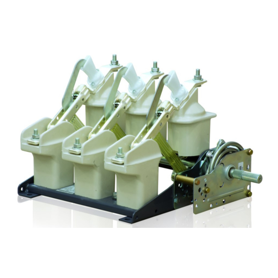
- Page 1 ® VersaRupter MV Indoor Switch 4.76-38 kV, 200-1200 A, 40 & 61 kA Installation, Operations, and Maintenance Manual...
- Page 2 VersaRupter switches allow 100% certainty to determine the position of the main contacts. ABB recommends to verify the position of the main knives before and after each op- eration. ABB recommends installing switches in applications where it is possible to visually check the position of the main knives e.g.
-
Page 3: Table Of Contents
Mounting the NM Motor Operator on K-Mechanism Mounting the NM Motor Operator on A-Mechanism Mounting the NM Motor Operator on Left Side of VersaRupter A-mech Mounting the NM Motor Operator on Left Side of VersaRupter K-mech Installing the Type E Ground Switch on VersaRupter... -
Page 4: Versarupter Mv Indoor Switch | Installation And Operation Manual
Table of Contents Direct Drive Handle Right Side Direct Drive Handle Left Side HE/HM Handles Renewal Parts List Notes VersaRupter MV Indoor Switch | Installation and Operation Manual... -
Page 5: Introduction
For issues not dis- cussed in this instruction bulletin, contact the factory as indicat- ed on the back cover. Never lift the VersaRupter by the switch blades, operating shaft, or insulators; damage and misalignment will occur when lifted by these parts. -
Page 6: Installation And Mounting
Figure 4 WARNING The VersaRupter switch blades move rapidly with great force. Always stay clear of these moving parts to avoid serious bodily injury. The A-mechanism is a stored energy device that can release its energy with great force and speed after a very small rotation of the shaft. - Page 7 If the VersaRupter is equipped with a grounding equipped). For all other handles, engage padlocks or switch, it may be closed after confirming the Ver- key interlocks (if equipped). saRupter is open, Figure 103. VersaRupter MV Indoor Switch | Installation and Operation Manual...
- Page 8 Disengage any padlocks or key interlocks required to 103. operate the VersaRupter (if equipped). If the VersaRupter is equipped with the fuse tripping For HE handles, apply the removable handle on the system, ensure that none of the fuse striker pins have splined shaft of the manual drive, pull the arrestor been activated.
- Page 9 M12 bolts through the mounting holes in the frame. Installation of the VersaRupter Use caution not to deform the base of the VersaRupter during installation. This could lead to the following prob- lems: Increased moment of force on the VersaRupter shaft.
-
Page 10: Mounting And Wiring The Shunt Trip
A-mechanism and mark the hole that will provide the maximum rotation of the white disk if the linkage is pulled. An exam- ple is shown in figure 7. Figure 7 VersaRupter MV Indoor Switch | Installation and Operation Manual... - Page 11 10, to which the coil wires are attached. The plug can be wired separate from the coil and plugged back in to complete the circuit. Figure 10 VersaRupter MV Indoor Switch | Installation and Operation Manual...
-
Page 12: Mounting The Open Fuse Auxiliary Switch
13. Rotate the white disk with your finger and mark the hole directly adjacent to the white roller on the switch as shown in figure 14. Figure 13 Figure 14 VersaRupter MV Indoor Switch | Installation and Operation Manual... - Page 13 Once adjusted properly, secure the switch with a 13 mm socket and Phillips screw driver. Install the cir-clip onto the half-moon shaft to secure the white disk as shown in figure 17. Figure 16 Figure 17 VersaRupter MV Indoor Switch | Installation and Operation Manual...
-
Page 14: Mounting The Open Fuse Auxiliary Switch On Motor Bracket
Rotate the white plastic disc to its maximum rotation and Figure 19 mark the hole adjacent to the white roller on the open fuse auxiliary switch as shown in figure 20. Figure 20 VersaRupter MV Indoor Switch | Installation and Operation Manual... - Page 15 If the setup is correct, secure the white disc with the provided cir-clip onto the half moon shaft. Figure 22 VersaRupter MV Indoor Switch | Installation and Operation Manual...
-
Page 16: Mounting An Open Fuse Auxiliary Switch With A Shunt Trip
Rotate the white disk until it reaches its maximum displacement and mark the hole adjacent to the white roller on the open fuse auxiliary switch as shown in figure 25. Figure 24 Figure 25 VersaRupter MV Indoor Switch | Installation and Operation Manual... - Page 17 28. An audible click should be heard from the switch. If not, relocate the long bolt and nuts to the appropriate hole. Figure 27 Figure 28 VersaRupter MV Indoor Switch | Installation and Operation Manual...
- Page 18 Once adjusted properly, secure the switch with a 13 mm socket and Phillips screw driver. Install the clamp onto the half-moon shaft to secure the white disk to the A-mechanism. Figure 30 VersaRupter MV Indoor Switch | Installation and Operation Manual...
-
Page 19: Mounting The Auxiliary Switch
6 mm Allen key as seen in figure 32. Connect the lever on the auxiliary switch to the lever on the jack shaft and secure it with the provided clamp shown in figure 33. Figure 32 Figure 33 VersaRupter MV Indoor Switch | Installation and Operation Manual... -
Page 20: Installing The Left Hand Shaft Extension
The left hand shaft extension allows for the operation of Figure 34 the VersaRupter from the left side of the switch. The op- erating mechanism is always mounted on the right side of the switch so it is necessary to install a left hand shaft extension if operation from the left side is desired or re- quired. -
Page 21: Mounting The Nm Motor Operator On K-Mechanism
VersaRupter. Further instructions can be found in the manual for the NM motor operator supplied with the motor concerning wiring and other data. Use M8 or 5/16” bolts and hardware to secure mounting bracket and motor. - Page 22 Slide the NM motor onto the splined shaft of the K- Figure 40 mechanism and secure it with bolts, washer, lock washers, and nuts as shown in figure 40. Figure 41 VersaRupter MV Indoor Switch | Installation and Operation Manual...
-
Page 23: Mounting The Nm Motor Operator On A-Mechanism
VersaRupter. Further instructions can be found in the manual for the NM motor operator supplied with the motor concerning wiring and other data. Use M8 or 5/16” bolts and hardware to secure mounting bracket and motor. - Page 24 Slide the NM motor onto the splined shaft of the A- Figure 45 mechanism and secure it with bolts, washer, lock washers, and nuts as shown in figure 45. Figure 46 VersaRupter MV Indoor Switch | Installation and Operation Manual...
-
Page 25: Mounting The Nm Motor Operator On Left Side Of Versarupter A-Mech
Mounting the NM Motor Operator on Left Side of VersaRupter A-mech A left hand shaft extension is supplied if the NM motor is Figure 47 ordered for left side applications. Use M8 or 5/16” bolts and hardware to secure mounting bracket and motor. -
Page 26: Mounting The Nm Motor Operator On Left Side Of Versarupter K-Mech
Mounting the NM Motor Operator on Left Side of VersaRupter K-mech A left hand shaft extension is supplied if the NM motor is Figure 51 ordered for left side applications. Use M8 or 5/16” bolts and hardware to secure mounting bracket and motor. -
Page 27: Installing The Type E Ground Switch On Versarupter
Figure 57 the kit. Secure the Type E grounding switch to the lower por- tion of the VersaRupter frame using a 13 mm socket as shown in figure 57. Close the grounding switch, figure 58, with a remova- ble handle to align the stationary contacts and tighten the bolts using a 19 mm socket securing the stationary contacts. -
Page 28: Installing The Type E Ground Switch On Versarupter Fuse Base
Installing the Type E Ground Switch on VersaRupter Fuse Base The grounding switch allows the lower terminals of the Figure 59 fuse base to be grounded. The grounding switch must be mechanically interlocked with the VersaRupter so that it cannot be closed the same time the VersaRupter is closed. -
Page 29: Installing The Mechanical Interlock
The mechanical interlock spans the distance between the Figure 63 VersaRupter left hand shaft extension and the left shaft of the ground switch. The mechanical interlock may also be installed on the right side of the switch allowing the oper- ating handle to be operated from the left side of the switch. - Page 30 Positively ground the braided ground connection found on the ground switch to the enclosure grounding sys- tem. Figure 67 Note: For A-mech applications, A-mech must be charged in order to close the ground switch. VersaRupter MV Indoor Switch | Installation and Operation Manual...
-
Page 31: Installing The Bottom Mounted Fuse Base With Fuse Tripping
Bases are available to be mounted on either the top (line side) or bottom (load side) of the VersaRupter. The terminals of the switch pro- Figure 69 vide the mounting points for the fuse clips and the optional fuse trip accessories. - Page 32 (3), and place the left side of the release shaft (1) into the hole found on the left side of the Figure 73 VersaRupter frame. Refer to figure 75. Figure 74 Figure 75 VersaRupter MV Indoor Switch | Installation and Operation Manual...
- Page 33 12 mm. If the VersaRupter does not open when adjusted as mentioned above, the adjustment must be repeated. VersaRupter MV Indoor Switch | Installation and Operation Manual...
-
Page 34: Installing The Top Mounted Fuse Base With Fuse Tripping
Bases are available to be mounted on either the top (line side) or bottom (load side) of the VersaRupter. The terminals of the switch pro- vide the mounting points for the fuse clips and the optional Figure 81 fuse trip accessories. - Page 35 (3), and place the left side of the release shaft (1) into the hole found on the left side of the VersaRupter frame. Refer to figure 87. Figure 85 Figure 86 Figure 87 VersaRupter MV Indoor Switch | Installation and Operation Manual...
- Page 36 12 mm. If the VersaRupter does not open when adjusted as mentioned above, the adjustment must be repeated. VersaRupter MV Indoor Switch | Installation and Operation Manual...
-
Page 37: Mounting The He/Hm Operating Handles
Seeger ring. 12. Warning! Always apply the information label supplied with the HE/HM handle during installation. Labels must be close to the body of the handle for proper notification during service. VersaRupter MV Indoor Switch | Installation and Operation Manual... -
Page 38: Installing The Chain Drive Handle
10 times using the handle and make final adjustments to the turnbuckles. If properly ad- justed, the handle should be approximately 3/4” to 7/8” from the handle stop in either position when the switch trips. VersaRupter MV Indoor Switch | Installation and Operation Manual... -
Page 39: Installing The Direct Drive Handle
Installing the Direct Drive Handle Refer to the drawings “Direct Drive Handle Right Side/Left Side” for details. Ensure that the VersaRupter is closed and the handle is in the closed position. Mount the direct drive handle to the switchgear enclo- sure using a 9/16”... -
Page 40: Installing The Back Connect Kit
The back connect bus bar is attached to the Ver- saRupter terminals with the hardware provided with the VersaRupter. The back connect bus bars may be connected to cabling or bus work as needed. For die- lectric purposes, bus boots may be installed at the termination of the back connect bus bar and the field connections. -
Page 41: Installing The K-Mechanism
These operations must be carried out by specialists only! Improper installation may result in serious injury or death. Ensure that the VersaRupter is in the open position. The jack shaft should appear as in figure 95 when Figure 96 looking at it from the right side, where the mechanism will be installed. -
Page 42: Installing The A-Mechanism
Improper installation may result in serious injury or death. Ensure that the VersaRupter is in the open position. The jack shaft should appear as in figure 99 when looking at it from the right side, where the mechanism Figure 100 will be installed. -
Page 43: Service And Maintenance
ISOFLEX TOPAS NCA 52. If the VersaRupter is placed in a very humid and polluted area, which will reduce the track- e. Safe distanced to earthed parts or to other live ing resistance, it is recommended to polish the insulators parts must be kept. - Page 44 Fig- ure 105b. All four contact points on the main contacts must be in touch with the fixed contacts. VersaRupter MV Indoor Switch | Installation and Operation Manual...
-
Page 45: Replacement Of Parts 5-27 Kv
10 mm deep by the self tap- ping screw before mounting. Remove the screw and blow the threaded holes clean. See the procedures on the fol- lowing pages regarding installation. VersaRupter MV Indoor Switch | Installation and Operation Manual... - Page 46 These operations must be carried out by specialists only! Improper installation may result in serious injury or death. Ensure the VersaRupter is in the open position and both operating springs discharged. Remove the cir-clip and washer (2.1) attaching the draw bar to the main shaft. Eccentric bolt does not have to be loosened.
- Page 47 (2.3), shown in figure 113, or by moving the insu- lator (2.4). Eccentric bolt should be torqued to 32 Figure 112 Figure 113 VersaRupter MV Indoor Switch | Installation and Operation Manual...
- Page 48 Replacement of Fixed Contact and Arcing Chamber Ensure the VersaRupter is in the open position and both Figure 114 operating springs discharged. Using a T40 Torx socket, unscrew the two screw (3.1) and lift up the arcing chamber and the thermal disc (3.4 / 600 A) while pressing the main contact (3.5)
- Page 49 “Torque Values for Self Tapping Screws” section. Check correct position of the arcing contacts and test for correct functionality. Grease the contact area with ISOFLEX TOPAS NCA 52. Figure 119 VersaRupter MV Indoor Switch | Installation and Operation Manual...
- Page 50 Remember to mount the piston with piston rod (3.10). For correct torque values see the “Torque Values for Self Tapping Screws” section. Do not forget to install the washer and spring washer for the self tapping screws. VersaRupter MV Indoor Switch | Installation and Operation Manual...
- Page 51 “Replacement of Contact Knife with Draw Bar”. Notes: For correct torque values see the “Torque Values for Self Tapping Screws” section. Do not forget to install the washer and spring washer for the self tapping screws. VersaRupter MV Indoor Switch | Installation and Operation Manual...
- Page 52 Attach the new insulator to the frame by the two self tapping screws (4.3). Attach the fuse clips and contact block to the top of the insulator and secure with screws (4.2). VersaRupter MV Indoor Switch | Installation and Operation Manual...
-
Page 53: Replacement Of Parts 38 Kv
These operations must be carried out by specialists only! Improper installation may result in serious injury or death. Contact Knives Ensure the VersaRupter is open and the A-mechanism is not charged (if equipped). Detach the draw bar from the jack shaft by removing Figure 124 the cir-clip and washer as shown in figure 123. - Page 54 Replacement of Parts 38 kV Draw bars Figure 125 Ensure the VersaRupter is open and the A-mechanism is not charged (if equipped). Remove the bolt found in figure 125. Push the top of the arcing blade such that the draw bar bolt in figure 126 will be exposed and can be pushed out, freeing the upper end of the draw bar.
- Page 55 Improper installation may result in serious injury or death. Replacing the lower insulator Ensure the VersaRupter is open and the A-mechanism is not charged (if equipped). Remove the contact, item 2 in figure 128, from the lower insulator.
- Page 56 Improper installation may result in serious injury or death. Replacing the upper insulator Ensure the VersaRupter is open and remove the operating mechanism from the VersaRupter. Detach all of the draw bars from the jack shaft. Rotate the jack shaft as if the switch was closing.
- Page 57 Replacement of Parts 38 kV Changing the piston Figure 130 Ensure the VersaRupter is closed and remove the operating mechanism from the VersaRupter. Disconnect the lower part of the draw bar from the jackshaft by removing the cir-clip in figure 130.
-
Page 58: Torque Values For Self Tapping Screws
Torque Values for Self Tapping Screws Figure 132 5-27 kV Figure 133 38 kV VersaRupter MV Indoor Switch | Installation and Operation Manual... -
Page 59: Outline
Outline Drawing 8.25 kV : 200/600 A : 40 kA VersaRupter MV Indoor Switch | Installation and Operation Manual... - Page 60 Outline Drawing 8.25 kV : 1200 A : 40 kA VersaRupter MV Indoor Switch | Installation and Operation Manual...
- Page 61 Outline Drawing 15 kV : 200/600 A : 40 kA VersaRupter MV Indoor Switch | Installation and Operation Manual...
- Page 62 Outline Drawing 15 kV : 1200 A : 40 kA VersaRupter MV Indoor Switch | Installation and Operation Manual...
- Page 63 Outline Drawing 15/15.5 kV : 600/1200 A : 61 kA VersaRupter MV Indoor Switch | Installation and Operation Manual...
- Page 64 Outline Drawing 17 kV : 200/600 A : 40 kA VersaRupter MV Indoor Switch | Installation and Operation Manual...
- Page 65 Outline Drawing 17 kV : 1200 A : 40 kA VersaRupter MV Indoor Switch | Installation and Operation Manual...
- Page 66 Outline Drawing 27 kV : 200/600 A : 40 kA VersaRupter MV Indoor Switch | Installation and Operation Manual...
- Page 67 Outline Drawing 27 kV : 1200 A : 40 kA VersaRupter MV Indoor Switch | Installation and Operation Manual...
- Page 68 Outline Drawing 38 kV : 600/800 A VersaRupter MV Indoor Switch | Installation and Operation Manual...
-
Page 69: Back Connect Kit
Back Connect Kit 5 kV : 200 / 600 A : 40 kA VersaRupter MV Indoor Switch | Installation and Operation Manual... - Page 70 Back Connect Kit 15 kV : 200 / 600 A : 40 kA VersaRupter MV Indoor Switch | Installation and Operation Manual...
- Page 71 Back Connect Kit 17 kV : 200 / 600 A : 40 kA VersaRupter MV Indoor Switch | Installation and Operation Manual...
- Page 72 Back Connect Kit 27 kV : 200 / 600 A : 40 kA VersaRupter MV Indoor Switch | Installation and Operation Manual...
- Page 73 Back Connect Kit 15 kV : 600 A : 61 kA VersaRupter MV Indoor Switch | Installation and Operation Manual...
-
Page 74: Auxiliary Switch Kit
Auxiliary Switch Kit VersaRupter MV Indoor Switch | Installation and Operation Manual... -
Page 75: Chain Drive Assembly
Chain Drive Assembly VersaRupter MV Indoor Switch | Installation and Operation Manual... -
Page 76: Left Hand Shaft Extension
Left Hand Shaft Extension VersaRupter MV Indoor Switch | Installation and Operation Manual... -
Page 77: Mechanical Door Interlock
Mechanical Door Interlock VersaRupter MV Indoor Switch | Installation and Operation Manual... -
Page 78: Direct Drive Handle Right Side
Direct Drive Handle Right Side VersaRupter MV Indoor Switch | Installation and Operation Manual... -
Page 79: Direct Drive Handle Left Side
Direct Drive Handle Left Side VersaRupter MV Indoor Switch | Installation and Operation Manual... -
Page 80: He/Hm Handles
HE/HM Handles VersaRupter MV Indoor Switch | Installation and Operation Manual... -
Page 81: Renewal Parts List
2RGA024432A0001 (sprocket), 650107C00 (set screw) Closed and Open indicator labels 2RGA024746P0002 (Closed), 2RGA024746P0001 (Open) Caution labels, English and French 2RGA024120P0001 (English), 2RGA024126P0001 (French) Removable link assembly 576986GRB Offset link assembly 576987GRB Turn buckle 159798301 VersaRupter MV Indoor Switch | Installation and Operation Manual... -
Page 82: Notes
Notes VersaRupter MV Indoor Switch | Installation and Operation Manual... - Page 83 While every effort has been made to assure accuracy, the information Phone: +1 252 827 2121 in this document is subject to change without notice. Customer service : +1 252 827 3251 E-Mail: connie.jenkins@us.abb.com © Copyright 2011 ABB Inc. All rights reserved. www.abb.com/mediumvoltage...