
Related Manuals for ABB ATS022


Summary of Contents for ABB ATS022
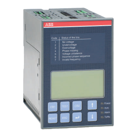
- Page 1 Automatic transfer switch ATS022 Installation and operating instructions 1SDH000760R0002...
-
Page 3: Table Of Contents
Installation ........................21 Automatic transfer switch ATS022, door mounting ..............21 Automatic transfer switch ATS022, DIN-rail mounting ...............22 Connecting ........................23 Power circuit of the automatic transfer switch ATS022 ..............23 Control circuit ..........................23 6.2.1 Control circuit of the automatic transfer switch ATS022 ............24 Technical data ......................... -
Page 4: Introduction
Installation and operating instructions, ATS022 1. Introduction 1. Introduction This manual describes the installation and the basic operation of the automatic transfer switch ATS022 used with circuit breakers. 1.1 Use of symbols Hazardous voltage: warns about a situation where a hazardous voltage may cause physical injury to a person or damage to equipment. -
Page 5: Safety Notes
1.3 Safety notes If there are doubts about safety use, the unit must put out of service. The automatic transfer switch ATS022 must be prevented from operating the circuit breaker before accessing the circuit breakers performing maintenance on circuit breakers or any electrical circuits powered by them... -
Page 6: Explanations Of Abbreviations And Terms
Switching delay, time after which ATS022 sends an opening command to the protection device on the normal line TCE: Close emergency delay, time after which ATS022 sends a closing command to the protection device on the emergency line TBS: Back switching delay, time after which ATS022 sends an opening command to the... -
Page 7: Product Overview
Figure 2.1 Network line - GenSet line B. Network line a – Network line b In case of loss of the main’s network the ATS022 device manages the switching to a second line used as an emergency source. Figure 2.2... -
Page 8: Functions Of Automatic Transfer Switch Ats022
The status of ATS022 can be monitored through the Modbus RTU connection. The ATS022 has a graphic display where the user is able to check the settings and get all the information about status of the ATS022. - Page 9 Installation and operating instructions, ATS022 2. Product overview The device has an external auxiliary power supply possibility for guarantying an uninterrupted power supply for the protection devices in the case where they are not powered through the control circuit. From the display, one can choose whether the N-line is connected or not.
-
Page 10: Description
Installation and operating instructions, ATS022 3. Description 3. Description 3.1 ATS outputs 3.1.1 Opening/closing command to circuit breakers, DO1...DO4 The output relays command the circuit breakers to open and close its releases. The confi guration of the output relays has been designed to allow the command of any type of motor operator through a direct connection. -
Page 11: Cb Withdrawn
A Gen-set alarm prevents switching to the emergency line. In the case of the power supply from the emergency line, when an alarm occurs, ATS022 keeps the line 2 with logic OFF; to enable the logic the alarm must be reset. -
Page 12: Voltage Sensors Input
TBS = Back switching delay, 0...30 s Figure 3.1 Automatic Switching Sequences 3.3 Application scenarios The ATS022 can be used in different installation scenarios: Two transformer incoming lines One transformer incoming line and an emergency generator on the emergency line 1SDH000760R0002, L4106... -
Page 13: Two Transformer Incoming Lines
If Line 1 (= the normal line) comes back, after the set time delay (TBS) the ATS022 sends an opening command to the protection device on the emergency line and the closing command to the protection device on the normal line is executed after a set time delay (TCN). - Page 14 Protection devices do not respond Opening Command During the switching sequence, the ATS022 sends the opening command to the protection device on the normal line. If this is not effectively opened in fi ve seconds, the “Open 1 Failure” alarm is activated and the Alarm LED will be switched ON.
-
Page 15: Transformer On Normal Line And Generator On Emergency Line
Missing of both lines The missing of both lines is indicated by a blinking Power LED. In this case, the ATS022 will be in a power saving state. If both lines are missing more than one minute, the ATS022 will shut down. -
Page 16: Special Scenarios
Two transformers and bus tie (Managing secondary loads): In this scenario, the ATS022 has to be able to control a third protection device used by the bus tie. ATS022 acquires the open/closed status of this device with digital input DI11 and by activating DO11 ATS022 is able to disconnect the secondary loads. -
Page 17: Operating
4. Operating 4. Operating Before using of the automatic transfer switch ATS022, read carefully chapter 1 “Safety notes” in order to avoid malfunctions or dangerous operating conditions. Never open any covers on the product. There may be dangerous external control voltages inside the ATS022 automatic transfer switch even if the voltage is turned off. - Page 18 Installation and operating instructions, ATS022 4. Operating To select the operating line by the automatic transfer switch ATS022 in Manual Mode: a. Push the appropriate CB1 or CB2 key b. When pushing the CB1 key (see the Figure 4.2/k), the circuit breaker CB1 will be in the ON position (the status and the line indication, see the Figure 4.2/l) and the circuit breaker CB2 will be in the...
-
Page 19: Automatic Transfer Switch Ats022 In Automatic Mode
Manual Mode control 4.2 Automatic transfer switch ATS022 in Automatic Mode Selecting the automatic transfer switch ATS022 to the Automatic Mode: a. Make sure that power LED is ON, see the Figure 4.4/j. b. Push the RESET key once /k. -
Page 20: Test Sequence
When pushing the TEST key, the automatic transfer switch (ATS022) enters the test sequence in which it is possible to simulate switching and back-switching sequences step-by-step, by pressing the TEST key. ATS022 must be in MANUAL mode before entering the test sequence. Exiting from test sequence is done by RESET key. -
Page 21: Installation
The automatic transfer switch ATS022 can be mounted on the door or the DIN-rail. 5.1 Automatic transfer switch ATS022, door mounting The automatic transfer switch ATS022 can be mounted on the door with the fastener, see Figure 5.1. Door drilling according to Figure 5.1. -
Page 22: Automatic Transfer Switch Ats022, Din-Rail Mounting
Installation and operating instructions, ATS022 5. Installation 5.2 Automatic transfer switch ATS022, DIN-rail mounting The automatic transfer switch ATS022 can be mounted on the 35 mm DIN-rail, see the Figure 5.2. Door drilling, if needed, according to Figure 5.2. 35mm EN 50022 Ø... -
Page 23: Connecting
Before starting work, make sure that the circuit breaker is de-energised. 6.1 Power circuit of the automatic transfer switch ATS022 Operating and measuring voltage area on 3 phase system Main voltage: 100Vac - 480Vac (±20%) -
Page 24: Control Circuit Of The Automatic Transfer Switch Ats022
Installation and operating instructions, ATS022 6. Connecting 6.2.1 Control circuit of the automatic transfer switch ATS022 LINE 1 LINE 2 ATS022 Command disconnections protection devices Logic enable/ disable not used not used not used Figure 6.2 Control circuit diagram ATS022... - Page 25 6. Connecting Installation and operating instructions, ATS022 Connectors, ATS022 Figure 6.3 Connectors, ATS022 Con- Description Con- Description nector nector X11:1 Normal line LN1: L1 X29:1 X11:2 Normal line LN1: L2 X29.2 not used X11:3 Normal line LN1: L3 X29:3 not used...
-
Page 26: Technical Data
Installation and operating instructions, ATS022 7. Technical data 7. Technical data 7.1 Automatic transfer switch ATS022, power circuits Power circuit Value ATS022 Rated operational voltage U 100 - 480 Vac ±20% Phase - neutral 57.7 - 277 Vac ±20% Rated frequency 50 –... -
Page 27: Using Automatic Transfer Switch Ats022
8.2 Confi guration 8.2.1 Keypad RESET Selecting the automatic transfer switch ATS022 to the manual or automatic mode. An active alarm is set off by pushing the RESET key. TEST key Setting the automatic transfer switch to test sequence in which it is possible to simulate switching and back-switching sequences step-by-step, by pressing the TEST key. -
Page 28: Leds
A green Auto LED signals the automatic or the manual mode. When the automatic transfer switch ATS022 is in automatic mode, the Auto LED is ON. When the device is in manual mode,the Auto LED is OFF. In test sequence the Auto LED is blinking. -
Page 29: Display
Installation and operating instructions, ATS022 8. Using automatic transfer switch ATS022 8.2.3 Display The display is a graphic display with following menu pages: 8.2.3.1 Default page Default page shows the status of the protection devices and the status of two monitored lines and eventually of the generator. - Page 30 Installation and operating instructions, ATS022 8. Using automatic transfer switch ATS022 8.2.3.2 Main Menu page From Default page is entered to Main Menu page by pushing the Enter key. Main Menu page is the main page that allows entering in all the confi guration sub-pages: Figure 8.6...
- Page 31 Installation and operating instructions, ATS022 8. Using automatic transfer switch ATS022 Rated Operational Voltage U Rated Operational Voltage U is the rated voltage of the system. Value is announced as main voltage/ phase voltage, Volts. Factory setting is 400/230 V.
- Page 32 Installation and operating instructions, ATS022 8. Using automatic transfer switch ATS022 Protection Devices User can choose whether protection devices is CBs or CBs + Bus Tie. CBs is the default. Figure 8.11 Protection Devices, CBs is the default LN1: 1...
- Page 33 Installation and operating instructions, ATS022 8. Using automatic transfer switch ATS022 8.2.3.4 Device confi guration In this sub-page you can set the threshold of all monitored parameters and the time delay, see the table 8.3. You can change the password in this subpage. The password consists of four numbers, and is chosen with the arrow and enter keys.
- Page 34 Installation and operating instructions, ATS022 8. Using automatic transfer switch ATS022 Frequency Thresholds User can set frequency thresholds both minimum and maximum values. Factory settings are min -1% and max 1%. Figure 8.17 Frequency Threshold, factory settings: min -1%, max +1%...
- Page 35 Factory settings are Modbus address 1, Modbus Baud Rate 9600, Modbus Stop Bit 1 and Modbus Parity None. Tx/Rx LED indicates data transmission: LED is ON only when data is transmitted from the ATS022. Figure 8.19 Modbus Language Selection In this page it is possible to choose the language.
- Page 36 Installation and operating instructions, ATS022 8. Using automatic transfer switch ATS022 Retype New Password The new password has to be confi rmed by retyping it. After confi rmation, the user is returned to the Device Confi guration menu and on the bottom of the display the message PASSWORD CHANGED is shown.
-
Page 37: Communication Via Modbus
Figure 8.25 Alarm Log: 20 latest alarms, Clear Log will empty the log 8.2.4 Communication via Modbus An RS485 link is used to connect ATS022 with a PC or a PLC over a distance of 500 meters using Modbus protocol: RS485... - Page 38 8. Using automatic transfer switch ATS022 The confi guration of ATS022 can be done only by display and keypad, but the status information of the monitored lines and of the ATS022 can be monitored via Modbus. The following information is available: Func.
-
Page 39: Technical Data Of The Automatic Transfer Switch
In system with rated frequency is 16 2/3 an AUX voltage have to be used; if rated voltage is higher than 100Vac external voltage transformer must be used. Whenever ATS022 is used at low temperatures (lower than -10°C) it is advisable to use an external voltage to avoid any visualization problems on the graphical display. -
Page 40: Troubleshooting
Installation and operating instructions, ATS022 11. Troubleshooting 10. Troubleshooting 10.1 Alarms in ATS022 Alarms are showed with a dedicate message on the display of ATS022. Alarm messages are explained in the table below. Message Fault Action Open 1 Failure The protection device CB1 does not... - Page 41 Installation and operating instructions, ATS022 Notes 1SDH000760R0002, L4106...
- Page 42 Installation and operating instructions, ATS022 Notes 1SDH000760R0002, L4106...
- Page 44 БЦ Diamond Center оф.419 (044) 357-74-47 ABB SACE S.p.A The technical data and dimensions are valid at the time of printing. We reserve the right to An ABB Group company subsequent alterations. L.V. Breakers Via Baioni, 35 24123 Bergamo, Italy Telephone +39 035.395.111...