Table of Contents
Advertisement
Use
Siemens Building Technologies
Landis & Staefa Division
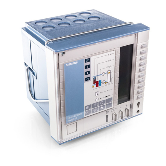
AEROGYR™
Controller
for central air handling
with single-speed or two-speed fans
Compact unit providing control and supervisory functions,
operating voltage AC 24 V, signal voltage DC 0...10 V.
Connection to Landis & Staefa building automation systems by means of
communication cards
In ventilating and air conditioning plants with
• hot water heating coils or electric air heater batteries
• direct expansion cooler batteries or chilled water cooling coils
• recirculated air dampers or heat recovery (HR) equipment
The RWI65.02 is used to:
• Control
– the room-supply air temperature or extract air-supply air temperature (cascade
control) with adjustable minimum and maximum limitations
– the room-supply air temperature or extract air-supply air temperature (cascade
control) with room or extract air-dependent shifting minimum and maximum
limitations (displacement ventilation)
– the supply air temperature
– the CO
/ VOC content of the room air (demand-controlled ventilation)
2
– single- or two-speed fans
– air coolers
– chillers
– HR equipment
– hot water heating coils (with preheating)
– electric air heater batteries (with fan overrun)
– circulators in hot or chilled water circuits (load- or outside temperature-dependent)
– air damper actuators (with recirculated start-up circuit for modulating dampers)
– regulating units in hot and chilled water circuits
3
204
.
RWI65.02
.
SW version 3.3
.
.
CM2N3204E / 05.2001
1/20
Advertisement
Table of Contents

Related Manuals for Siemens RWI65.02


Summary of Contents for Siemens RWI65.02
- Page 1 • hot water heating coils or electric air heater batteries • direct expansion cooler batteries or chilled water cooling coils • recirculated air dampers or heat recovery (HR) equipment The RWI65.02 is used to: • Control – the room-supply air temperature or extract air-supply air temperature (cascade control) with adjustable minimum and maximum limitations –...
- Page 2 1) Optional 2) Consists of operating card 2, operating instructions, and mounting instructions • When ordering the controller, please indicate the type reference RWI65.02. To ensure Ordering the unit is supplied with the correct language version of the instructions, indicate the type reference of the instructions required, e.g., ARG65.44 (for English, Swedish,...
- Page 3 The required mode of control can be selected. Control sequences and The RWI65.02 is a sequence controller with three modulating outputs (Y10 = heating, Y20 = cooling, Y30 = HR) and one switching output (Q13 / Q24 = cooling). It allows for operating action control sequences using both operating actions, for dampers and HR equipment.
- Page 4 Night purging active Room temperature limit (DtPnt 12) Delta (DtPnt 14) N m in (DtPnt 15) Outside temperature limit (DtPnt 13) End of Beginnning of occupancy time occupancy time CM2N3204E / 05.2001 Siemens Building Technologies 4/20 Landis & Staefa Division...
- Page 5 In the case of systems with recirculated air dampers, damper control is activated also. Here, Y30 minimum limitation, recirculated air start-up mode, and the frost protection controller with a higher priority act on the Y30 control signal. Siemens Building Technologies CM2N3204E / 05.2001 Landis & Staefa Division...
- Page 6 Switching the plant via control inputs E7 and E8 The functions of the manual switch on the RWI65.02 (operating level 1, buttons 1 to 4) can be provided by a 4-step rotary switch with two levels. • By the function "Extended operation": When a pulse (of at least 3 s) is fed to E7, the plant is operated at fan speed I;...
- Page 7 (adjustable from 0 to 5 min). • Rundown time When switching down from the second to the first speed, the RWI65.02 deactivates the second speed, and the first speed is activated only when the preset time has elapsed (adjustable from 0 s to 5 min).
- Page 8 "A" are present. For the effects of the fault status signals at the outputs of the RWI65.02, refer to the function flow diagrams on the last page of this data sheet.
- Page 9 Operation The RWI65.02 is operated from four operating levels: information level, setting level, scheduler program level, and commissioning level. Information level When the front door is closed, the display shows the following information:...
- Page 10 Display window with ten lines Function buttons to change the setpoints Configuring the unit The DIL switches for the configuration of the RWI65.02 are located behind the cover. To with DIL switches view or change settings, open the front door and remove the cover.
- Page 11 1) Fan overrun is automatically activated 2) Frost protection controller is automatically activated Communication cards The RWI65.02 can communicate with an active bus device (master) with the aid of AZI65... – the FLN (Floor Level Network) communication card AZI65.01 or –...
- Page 12 Settings The controller is supplied with factory set control functions and parameters. If required, configure the RWI65.02 for various logical functions such as electric heating which is also subject to specific safety regulations. You can change the configuration with the help of the built-in DIL switches.
- Page 13 Q33/Q44 Potential-free relay contact output, to switch fan speed II UP, UN Connections (2...3) for communication LG-Ni1000 Ω sensors = L&S standard Note: Control signal outputs Y20 and Q13/Q24 are available at the same time Siemens Building Technologies CM2N3204E / 05.2001 Landis & Staefa Division 13/20...
- Page 14 G G0 Wiring diagram 4: Measuring part with passive remote setting unit Wiring diagram 5: Measuring part with extract air temperature sensor for limit control (anti-icing protection with HR) CM2N3204E / 05.2001 Siemens Building Technologies 14/20 Landis & Staefa Division...
- Page 15 / VOC sensor with or without ventilation demand processor for demand-controlled ventilation ) (VOC) ) (VOC) Legend for wiring Controller RWI65.02 RVL55 with plug-in module AZY55.60 diagrams 1 to 7 Room or extract air temperature sensor QAA24 / QAM22... Supply air temperature sensor QAM22...
- Page 16 00.00...10.00 mm.ss 00.00 mm.ss Power up start delay 00.00...30.00 mm.ss 00.00 mm.ss − 10...+30 °C HR anti-icing protection Setpoint 1 °C P-band 1...100 K 10 K 00.00...04.00 mm.ss 01.00 mm.ss CM2N3204E / 05.2001 Siemens Building Technologies 16/20 Landis & Staefa Division...
- Page 17 Must be set if the controller is equipped with a communication module. If no communication module is used, the value set has no effect on the RWI65.02 If the RWI65.02 is equipped with the AZI65.3 LPB communication card, the communication address becomes the LPB device number with a range of 0 to 16 and a factory setting of 0.
- Page 18 Risk of frost Water On/delocked when Y10 ≥ 0 % Dark Off/interlocked Off/interlocked when Y10 ≥ 0 % On/delocked Flashing Off/interlocked (switch-off delayed) Dark (Y10 ≥ 0 %) 3204Z05E CM2N3204E / 05.2001 Siemens Building Technologies 18/20 Landis & Staefa Division...
- Page 19 Risk of frost Water On/delocked when Y10 ≥ 0 % Dark Off/interlocked Off/interlocked when Y10 ≥ 0 % On/delocked Flashing Off/interlocked (switch-off delayed) Dark (Y10 ≥ 0 %) 3204Z06E Siemens Building Technologies CM2N3204E / 05.2001 Landis & Staefa Division 19/20...
- Page 20 Dimensions 272,5 13,5 Panel cutout 152,6 Pg 11 17,5 106,5 24 30,3 1999 Siemens Building Technologies Ltd. Dimensions in mm CM2N3204E / 05.2001 Siemens Building Technologies 20/20 Landis & Staefa Division...