
Related Manuals for Yamaha HTR-N5060


Summary of Contents for Yamaha HTR-N5060
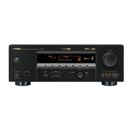
- Page 1 HTR-N5060 AV Receiver Ampli-tuner audio-vidéo OWNER’S MANUAL MODE D’EMPLOI BEDIENUNGSANLEITUNG MANUALE DI ISTRUZIONI MANUAL DE INSTRUCCIONES GEBRUIKSAANWIJZING ИНСТРУКЦИЯ ПО ЭКСПЛУАТАЦИИ...
- Page 2 Install this sound system in a well ventilated, cool, dry, clean YAMAHA will not be held responsible for any damage place – away from direct sunlight, heat sources, vibration, resulting from use of this unit with a voltage other than dust, moisture, and/or cold.
-
Page 3: Table Of Contents
Connecting a CD player, an MD player SET MENU ............66 or a tape deck............21 Using SET MENU........... 68 Connecting a YAMAHA iPod universal dock ..22 1 SOUND MENU............ 69 Connecting the network........... 23 2 INPUT MENU............74 Connecting a multi-format player, an external 3 NET/USB MENU.......... -
Page 4: Features
FEATURES Built-in 6-channel power amplifier Network features Minimum RMS output power LAN port to connect a PC and YAMAHA MCX-2000 or (1 kHz, 0.7% THD, 8 Ω) access the Internet radio via a LAN Front: 110 W + 110 W... -
Page 5: Getting Started
GETTING STARTED GETTING STARTED Supplied accessories Installing batteries in the remote control Check that you received all of the following parts. Remote control AM loop antenna CODE SET TRANSMIT POWER POWER STANDBY POWER SLEEP CD-R MULTI CH IN TUNER DOCK V-AUX SOURCE TV VOL... -
Page 6: Controls And Functions
CONTROLS AND FUNCTIONS CONTROLS AND FUNCTIONS Front panel VOLUME STANDBY l PRESET/TUNING h PRESET/TUNING FM/AM A/B/C/D/E MEMORY TUNING MODE NEXT LEVEL MAN'L/AUTO FM AUTO/MAN'L EDIT INPUT STRAIGHT PROGRAM PHONES SPEAKERS VIDEO AUX INPUT MODE MULTI CH INPUT EFFECT TONE CONTROL BASS/TREBLE VIDEO AUDIO... - Page 7 CONTROLS AND FUNCTIONS 8 MEMORY (MAN’L/AUTO FM) E BASS/TREBLE +/– Stores a preset station in the memory. Hold down this Adjusts the bass/treble balance of the front left and right button for more than 3 seconds to start automatic preset speakers in conjunction with TONE CONTROL tuning (see page 48).
-
Page 8: Remote Control
CONTROLS AND FUNCTIONS Remote control Controlling this unit This section describes the function of each control on the remote control used to control this unit. To operate other Set the component selector switch to AMP to control this components, see “REMOTE CONTROL FEATURES” on unit. - Page 9 D MULTI CH IN PC/MCX Selects the component connected to the MULTI CH Selects a PC server or YAMAHA MCX-2000 as the INPUT jacks as the input source when using an external sub input source of NET/USB. decoder, etc. (see page 38).
-
Page 10: Using The Remote Control
CONTROLS AND FUNCTIONS Controlling the TUNER functions Using the remote control Set the component selector switch to SOURCE and then The remote control transmits a directional infrared ray. press TUNER to select “TUNER” as the input source. Be sure to aim the remote control directly at the remote control sensor on this unit during operation. -
Page 11: Front Panel Display
1 Decoder indicators 6 DOCK indicator The respective indicator lights up when any of the Lights up when you station your iPod in a YAMAHA iPod decoders of this unit functions. universal dock (such as YDS-10 sold separately) connected to the DOCK terminal of this unit 2 ENHANCER indicator (see page 22). - Page 12 CONTROLS AND FUNCTIONS C VOLUME level indicator Indicates the current volume level. D PCM indicator Lights up when this unit is reproducing PCM (Pulse Code Modulation) digital audio signals. E STANDARD indicator Lights up when the “SUR. STANDARD” or “SUR. ENHANCED”...
-
Page 13: Rear Panel
See pages 19 and 21 for connection information. See page 26 for details. 7 DOCK terminal Use to connect a YAMAHA iPod universal dock (such as YDS-10 sold separately) where your iPod can be stationed. See page 22 for connection information. -
Page 14: Connections
Subwoofer (SW) The use of a subwoofer with a built-in amplifier, such as the YAMAHA Active Servo Processing Subwoofer System, is effective not only for reinforcing bass frequencies from any or all channels, but also for high fidelity reproduction of the LFE (low-frequency effect) channel included in Dolby Digital and DTS sources. -
Page 15: Connecting Speakers
CONNECTIONS Connecting speakers Be sure to connect the left channel (L), right channel (R), “+” (red) and “–” (black) properly. If the connections are faulty, no sound will be heard from the speakers, and if the polarity of the speaker connections is incorrect, the sound will be unnatural and lack bass. - Page 16 Connect surround speakers (4, 5) to these terminals. SURROUND BACK terminals Connect a surround back speaker (6) to these terminals. SUBWOOFER OUTPUT jack Connect a subwoofer with a built-in amplifier (7) (such as Speaker layout the YAMAHA Active Servo Processing Subwoofer System) to this jack.
- Page 17 CONNECTIONS Connecting the speaker cable Connecting the banana plug (except Europe model) The banana plug is a single-pole electrical connector Remove approximately 10 mm of insulation widely used to terminate speaker cables. from the end of each speaker cable and then twist the exposed wires of the cable together Banana plug to prevent short circuits.
-
Page 18: Information On Jacks And Cable Plugs
CONNECTIONS Information on jacks and cable plugs Audio jacks and cable plugs Video jacks and cable plugs COMPONENT VIDEO AUDIO DIGITAL AUDIO DIGITAL AUDIO VIDEO S VIDEO COAXIAL OPTICAL (White) (Red) (Orange) (Yellow) (Green) (Blue) (Red) Left and right Coaxial Optical Composite S-video... -
Page 19: Audio And Video Signal Flow
CONNECTIONS Audio and video signal flow Audio signal flow for AUDIO OUT (REC) Input Output AUDIO OUT (REC) DIGITAL AUDIO COAXIAL Digital audio DIGITAL AUDIO OPTICAL Analog audio AUDIO Digital output Analog output Note This unit handles digital and analog signals independently. Thus, audio signals input at the analog jacks are output only at the analog AUDIO OUT (REC) jacks. -
Page 20: Connecting A Tv
CONNECTIONS Connecting a TV Connect your TV to the VIDEO MONITOR OUT jack, the S VIDEO MONITOR OUT jack or the COMPONENT VIDEO MONITOR OUT jacks of this unit. CAUTION Do not connect this unit or other components to the AC power supply until all connections between components are complete. -
Page 21: Connecting A Dvd Player, A Dvd Recorder, A Vcr Or An Stb
CONNECTIONS Connecting a DVD player, a DVD recorder, a VCR or an STB Connect your DVD player, DVD recorder, VCR or STB (set-top box) using the same type of video connections as those made for your TV (see page 18). The cable TV receiver and the satellite receiver are examples of the STB. CAUTION Do not connect this unit or other components to the AC power supply until all connections between components are complete. - Page 22 CONNECTIONS Connecting a DVD recorder or a VCR AUDIO COMPONENT VIDEO VIDEO S VIDEO Component video out DVD recorder or Connecting an STB Cable TV receiver or satellite receiver Component video out AUDIO DIGITAL INPUT DTV/CBL OPTICAL DTV/ DTV/CBL DTV/CBL COMPONENT VIDEO VIDEO S VIDEO...
-
Page 23: Connecting A Cd Player, An Md Player Or A Tape Deck
CONNECTIONS Connecting a CD player, an MD player or a tape deck Connect your CD player, MD player or tape deck via analog and/or digital connections. CAUTION Do not connect this unit or other components to the AC power supply until all connections between components are complete. -
Page 24: Connecting A Yamaha Ipod Universal Dock
DOCK terminal of this unit as long as this unit is turned on. • Depending on the type of iPod, you may need to insert one of the iPod adapters supplied with a YAMAHA iPod universal dock (such as YDS-10 sold separately) into the dock slot before you station your iPod. -
Page 25: Connecting The Network
Configuration Protocol) server function. The following diagram shows a connection example where this unit is connected to one of the LAN ports on a 4-port router. To enjoy music files saved on your PC and YAMAHA MCX-2000 or access the Internet radio, each device must be connected properly in the network. -
Page 26: Connecting A Multi-Format Player, An External Decoder Or A Sound Processor
CONNECTIONS Connecting a multi-format player, Connecting a game console, a an external decoder or a sound video camera or a portable audio processor player This unit is equipped with 6 additional input jacks Use the VIDEO AUX jacks on the front panel to connect a (FRONT L/R, CENTER, SURROUND L/R and game console, a video camera or a portable audio player to SUBWOOFER) for discrete multi-channel input from a... -
Page 27: Connecting The Fm And Am Antennas
If you experience poor reception quality, Insert one of the AM loop antenna lead wires install an outdoor antenna. Consult the nearest authorized YAMAHA dealer or service center about outdoor antennas. into the AM ANT terminal. AM loop antenna... -
Page 28: Connecting The Power Cable
CONNECTIONS Connecting the power cable Once all connections are complete, plug the power cable into the AC wall outlet. (Canada model) AC OUTLETS To the AC wall outlet AC OUTLET(S) (SWITCHED) Australia model ............. 1 outlet Other models ............2 outlets Use these outlet(s) to supply power to any connected components. -
Page 29: Setting The Speaker Impedance
CONNECTIONS Setting the speaker impedance CAUTION Press PROGRAM l / h on the front panel to select “SP IMP.”. If you are to use 6 ohm speakers, set “SP IMP.” to The following display appears in the front panel “6ΩMIN” as follows BEFORE using this unit. 4 display. -
Page 30: Turning On And Off The Power
CONNECTIONS Turning on and off the power When all connections are complete, turn on this unit. STANDBY/ON STANDBY CODE SET TRANSMIT VOLUME POWER POWER STANDBY POWER POWER STANDBY SLEEP CD-R l PRESET/TUNING h MULTI CH IN PRESET/TUNING FM/AM A/B/C/D/E MEMORY TUNING MODE TUNER EDIT... -
Page 31: Basic Setup
BASIC SETUP BASIC SETUP The “BASIC SETUP” feature is a useful way to set up your system quickly and with minimal effort. Notes • Make sure you disconnect your headphones from this unit. • If you wish to configure this unit manually using more precise adjustments, use the detailed parameters in “SOUND MENU” (see page 69). - Page 32 BASIC SETUP Press d to select “SUBWOOFER” and then Press d to select “SETUP” and then j / i to j / i to select the desired setting. select the desired setting. PRESET/CH PRESET/CH ;BASIC SETUP ;BASIC SETUP ROOM: S >M ROOM: S >M .
- Page 33 BASIC SETUP Press j / i to select the desired setting. Press u / d to select a speaker and then j / i to adjust the balance. The selected speaker and the front left speaker (or the ;BASIC SETUP PRESET/CH surround left speaker) output a test tone in turn.
-
Page 34: Playback
PLAYBACK PLAYBACK CAUTION Extreme caution should be exercised when you play back CDs encoded in DTS. If you play back a CD encoded in DTS on a DTS-incompatible CD player, you will only hear some unwanted noise that may damage your speakers. Check whether your CD player supports CDs encoded in DTS. Also, check the sound output level of your CD player before you play back a CD encoded in DTS. - Page 35 PLAYBACK Press PROGRAM l / h on the front panel (or Rotate VOLUME on the front panel (or press VOLUME +/– on the remote control) to adjust press one of the sound field program the volume to the desired output level. selector buttons on the remote control) repeatedly to select the desired sound field VOLUME...
-
Page 36: Using Audio Features
USING AUDIO FEATURES USING AUDIO FEATURES Using SILENT CINEMA Selecting the night listening mode SILENT CINEMA allows you to enjoy multi-channel The night listening modes are designed to improve music or movie sound, including Dolby Digital and DTS listenability at lower volumes or at night. Choose either sources, through ordinary headphones. -
Page 37: Selecting The Input Mode
USING AUDIO FEATURES AUTO Automatically selects input signals in “NIGHT:CINEMA” and “NIGHT:MUSIC” adjustments are the following order: stored independently. (1) Digital signals (2) Analog signals Notes Selects only digital signals encoded in • You cannot use the night listening modes in the following DTS. -
Page 38: Adjusting The Speaker Level
USING AUDIO FEATURES Adjusting the speaker level Press SLEEP on the remote control repeatedly to set the amount of time. You can adjust the output level of each speaker while Each time you press SLEEP, the front panel display listening to a music source. This is also possible when changes as shown below. -
Page 39: Selecting The Compressed Music Enhancer Mode
USING AUDIO FEATURES Selecting the Compressed Music Press j / i on the remote control to adjust the Enhancer mode speaker output level. • Press i to increase the value. • Press j to decrease the value. Compression artifacts (such as the MP3 format) are created by a lossy compression scheme where the audio is Control range: –10 dB to +10 dB resampled to lower the bitrate and to remove sounds that... -
Page 40: Selecting The Multi Ch Input Component
USING AUDIO FEATURES Selecting the MULTI CH INPUT Set the component selector switch to AMP component and then press ENHANCER on the remote control repeatedly to select the desired Use this feature to select the component connected to the Compressed Music Enhancer mode. MULTI CH INPUT jacks (see page 24) as the input The following display appears in the OSD and the source. -
Page 41: Enjoying Multi-Channel Sources In 2-Channel Stereo
USING AUDIO FEATURES Enjoying multi-channel sources in Enjoying pure hi-fi stereo sound 2-channel stereo The “DIRECT STEREO” mode allows sources to bypass the decoders and DSP processors of this unit so that you You can mix down multi-channel sources to 2 channels can enjoy pure hi-fi sound from 2-channel PCM and and enjoy playback in 2-channel stereo. -
Page 42: Using Video Features
USING VIDEO FEATURES USING VIDEO FEATURES Signal format FORMAT Displaying the input source Signal format display. When this unit cannot detect a information digital signal, it automatically switches to analog input. You can display the format, sampling frequency, channel, Display status: Analog, Digital, DolbyD, DTS, MP3, PCM, WMA, --- bit rate and flag data of the current input signal. -
Page 43: Selecting The Osd Mode
USING VIDEO FEATURES Selecting the OSD mode You can display a gray background in the OSD when there is not video signal being input by setting “GRAY BACK” in “OPTION You can display the operating information of this unit on a MENU”... -
Page 44: Enjoying Surround Sound
ENJOYING SURROUND SOUND ENJOYING SURROUND SOUND Decoders Enjoying multi-channel sources in You can select from the following decoders depending on 6.1-channel surround the format of the source you are playing. If you connected a surround back speaker, use this feature Decoder Functions to enjoy 6.1-channel playback for multi-channel sources... -
Page 45: Enjoying 2-Channel Sources In Surround
ENJOYING SURROUND SOUND Enjoying 2-channel sources in SUR. STANDARD Functions surround Dolby Pro Logic processing for any PRO LOGIC sources Signals input from 2-channel sources can also be played back on multi-channels. Dolby Pro Logic II processing for PLII Movie movie sources Set the component selector switch to AMP Dolby Pro Logic II processing for... -
Page 46: Using Virtual Cinema Dsp
ENJOYING SURROUND SOUND Using Virtual CINEMA DSP Virtual CINEMA DSP allows you to enjoy the CINEMA DSP programs without surround speakers. It creates virtual speakers to reproduce the natural sound field. If you set “SUR. L/R SP” NONE” (see page 70), to “... -
Page 47: Recording
RECORDING RECORDING Recording adjustments and other operations are performed from the recording components. Refer to the operating instructions for those components. CAUTION The DTS signal is a digital bitstream. Attempting to digitally record the DTS bitstream will result in noise being recorded. Therefore, if you want to use this unit to record sources encoded in DTS, the following considerations and adjustments need to be made. -
Page 48: Fm/Am Tuning
FM/AM TUNING FM/AM TUNING There are 2 tuning methods: automatic and manual. Automatic tuning is effective when station signals are strong and there is no interference. If the signal from the station you want to select is weak, tune into it manually. You can also use the automatic and manual preset tuning features to store up to 40 stations (A1 to E8: 8 preset station numbers in each of the 5 preset station groups). -
Page 49: Manual Tuning
FM/AM TUNING Manual tuning Press TUNING MODE (AUTO/MAN’L) so that the AUTO indicator disappears from the front If the signal received from the station you want to select is panel display. weak, tune into it manually. TUNING MODE Note DISPLAY AUTO/MAN'L Manually tuning into an FM station automatically switches the tuner to monaural reception to increase the signal quality. -
Page 50: Automatic Preset Tuning
FM/AM TUNING Automatic preset tuning Press and hold MEMORY (MAN’L/AUTO FM) for more than 3 seconds. You can use the automatic preset tuning feature to store The preset station number as well as the MEMORY FM stations with strong signals up to 40 (A1 to E8: 8 and AUTO indicators flashes. -
Page 51: Manual Preset Tuning
FM/AM TUNING Automatic preset tuning options Manual preset tuning You can specify the preset number from which this unit stores FM stations and/or begins tuning toward lower You can also store up to 40 stations (A1 to E8: 8 preset frequencies. -
Page 52: Selecting Preset Stations
FM/AM TUNING Selecting preset stations Press PRESET/TUNING l / h to select a preset station number (1 to 8) while the You can tune into any desired station simply by selecting MEMORY indicator is flashing. the preset station group and number under which it was •... -
Page 53: Exchanging Preset Stations
FM/AM TUNING Exchanging preset stations Press PRESET/TUNING l / h on the front panel (or PRESET/CH u / d on the remote You can exchange the assignments of two preset stations control) to select the desired preset station with each other. The example below describes the number (1 to 8). - Page 54 FM/AM TUNING Select preset station “A5” using A/B/C/D/E and PRESET/TUNING l / h. “A5” and the MEMORY indicator flash in the front panel display. See “Selecting preset stations” on page 50. A/B/C/D/E l PRESET/TUNING h NEXT LEVEL Flashes MD/CD-R pTUNER V-AUX DTV/CBL VOLUME...
-
Page 55: Radio Data System Tuning (Europe Model Only)
RADIO DATA SYSTEM TUNING (EUROPE MODEL ONLY) RADIO DATA SYSTEM TUNING (EUROPE MODEL ONLY) Radio Data System (Europe model only) is a data transmission system used by FM stations in many countries. The Radio Data System function is carried out among the network stations. This unit can receive various Radio Data System data such as PS (program service), PTY (program type), RT (radio text), CT (clock time), and EON (enhanced other networks) when receiving Radio Data System broadcasting stations. -
Page 56: Using The Radio Data System Station Network
RADIO DATA SYSTEM TUNING (EUROPE MODEL ONLY) Using the Radio Data System Press PTY SEEK START on the remote station network control to start searching for all the available Radio Data System preset stations. Use this feature to receive the EON (enhanced other The name of the selected program type flashes and networks) data service of the Radio Data System station the PTY HOLD indicator lights up in the front panel... -
Page 57: Displaying The Radio Data System Information
RADIO DATA SYSTEM TUNING (EUROPE MODEL ONLY) Displaying the Radio Data System Press EON on the remote control repeatedly information to select one of the 4 Radio Data System program types (NEWS, AFFAIRS, INFO or Use this feature to display the 4 types of the Radio Data SPORT). - Page 58 RADIO DATA SYSTEM TUNING (EUROPE MODEL ONLY) Press FREQ/TEXT on the remote control repeatedly to select the desired Radio Data System display mode. FREQ/TEXT Frequency display • Select “PS” to display the name of the Radio Data System program currently being received. •...
-
Page 59: Sound Field Programs
The acoustics in your room could be changed to those of a concert hall, a dance floor, or a room with virtually any size at all. This ability to create sound fields at will is exactly what YAMAHA has done with the digital sound field processor. -
Page 60: Sound Field Program Descriptions
(DSP) chip containing several sound field programs which you can use to enhance your playback experience. The YAMAHA CINEMA DSP modes are compatible with all Dolby Digital, DTS, and Dolby Surround sources. Set “INPUT MODE” to “AUTO” (see page 35) to enable this unit to automatically switch to the appropriate digital decoder according to the input signal. -
Page 61: For Music Sources
SOUND FIELD PROGRAMS Remote control Sound field program Features Sources button MOVIE THEATER CINEMA DSP processing. This program reproduces the extremely wide sound field of a 70-mm movie theater in detail, making both the video and the sound Spectacle field incredibly real. This is ideal for any kind of video source encoded in Dolby Surround, Dolby Digital or DTS, especially large-scale movie productions. -
Page 62: Changing Sound Field Parameter Settings
SOUND FIELD PROGRAMS Changing sound field parameter Turn on the video monitor and then press settings DISPLAY on the remote control. The following display is shown in the OSD. You can enjoy good quality sound with the initial factory settings. Although you do not have to change the initial DISPLAY factory settings, you can change some of the parameters to ON SCREEN... -
Page 63: Sound Field Parameter Descriptions
SOUND FIELD PROGRAMS Sound field parameter descriptions You can adjust the values of certain digital sound field parameters so that the sound fields are recreated accurately in your listening room. Not all of the following parameters are found in every program. To change sound field parameter settings to suit your listening environment, see page 60 for details. - Page 64 SOUND FIELD PROGRAMS Sound field parameter Features ROOM SIZE Room size. Presence, surround, and surround back room sizes. Adjusts the apparent size of the surround sound field. The larger the value, the larger the surround sound field becomes. As the P.ROOM SIZE sound is repeatedly reflected around a room, the larger the hall is, the longer the time between S.ROOM SIZE...
- Page 65 SOUND FIELD PROGRAMS Sound field parameter Features REV.TIME Reverberation time. Adjusts the amount of time taken for the dense, subsequent reverberation sound to decay by 60 dB at 1 kHz. This changes the apparent size of the acoustic environment over an extremely wide range. Set a longer reverberation time for “dead” sources and listening room environments, and a shorter time for “live”...
- Page 66 SOUND FIELD PROGRAMS Sound field parameter Features REV.LEVEL Reverberation level. Adjusts the volume of the reverberation sound. The larger the value, the stronger the reverberation becomes. Control range: 0 to 100% Source sound REV. LEVEL Time 2ch Stereo 2-channel stereo direct. Bypasses the decoders and DSP processors of this unit for pure hi-fi stereo sound when playing 2-channel analog sources.
- Page 67 SOUND FIELD PROGRAMS Sound field parameter Features PRO LOGIC IIx Music Pro Logic IIx Music and Pro Logic II Music panorama. Sends stereo signals to the surround speakers as well as the front speakers for a wraparound effect. PRO LOGIC II Music PANORAMA Choices: OFF, ON PRO LOGIC IIx Music...
-
Page 68: Set Menu
SET MENU SET MENU You can use the following parameters in “SET MENU” to adjust a variety of system settings and customize the way this unit operates. Change the initial settings (indicated in bold under each parameter) to reflect the needs of your listening environment. - Page 69 SET MENU Network and USB menu 3 NET/USB MENU Use this menu to manually adjust the network and USB system parameters. Parameter Features Page A)NETWORK Configures the network settings automatically or manually. B)PLAY STYLE Adjusts the playback style. C)INFORMATION Displays the network system information. Option menu 4 OPTION MENU Use this menu to manually adjust the optional system parameters.
-
Page 70: Using Set Menu
SET MENU Using SET MENU Press u / d to select “MANUAL SETUP”. Use the remote control to access and adjust each PRESET/CH parameter. SET MENU ;BASIC SETUP . ;MANUAL SETUP STEREO MUSIC ENTERTAIN MOVIE SLEEP ENTER . ;SIGNAL INFO CD-R STANDARD SELECT... -
Page 71: Sound Menu
SET MENU 1 SOUND MENU Press u / d repeatedly and then press ENTER to select and enter the desired Use this menu to manually adjust any speaker settings or submenu. compensate for video signal processing delays when using The following display is an example where LCD monitors or projectors. - Page 72 SET MENU Center speaker CENTER SP Surround back speakers SUR. B SP Choices: NONE, SML, LRG Choices: NONE, SML, LRG SUR. B SP CENTER SP NONE >SML NONE >SML • Select “NONE” (none) if you did not connect a surround back speaker. The surround back channel •...
- Page 73 SET MENU CROSSOVER Crossover Speaker level B)SPEAKER LEVEL Use this feature to select a crossover frequency of all the Use this feature to manually balance the speaker levels speakers set to “SML” (or “SMALL”) or to “NONE” in between the front left or surround left speakers and each “SPEAKER SET”...
- Page 74 SET MENU Speaker distance C)SP DISTANCE Center graphic equalizer D)CENTER GEQ Use this feature to manually adjust the distance of each Use this feature to adjust the built-in 5-frequency band speaker and the delay applied to the respective channel. (100Hz, 300Hz, 1kHz, 3kHz and 10kHz) graphic Ideally, each speaker should be the same distance from the equalizer for the center channel so that the tonal quality of main listening position.
- Page 75 SET MENU Dynamic range Audio settings F)DYNAMIC RANGE G)AUDIO SET Use this feature to select the amount of dynamic range Use this feature to adjust the overall audio settings of this compression to be applied to your speakers or unit. headphones.
-
Page 76: Input Menu
SET MENU For OPTICAL INPUT jacks 2, 3 and 4 2 INPUT MENU OPTICAL IN (2) OPTICAL IN (3) Use this menu to reassign the input/output jacks, select the OPTICAL IN (4) input mode or rename the input source. Choices: (2) CD, MD/CD-R, DVD, DTV/CBL, V-AUX, 2 INPUT MENU (3) CD, MD/CD-R, DVD, DTV/CBL, V-AUX, . - Page 77 SET MENU Input mode B)INPUT MODE Press j / i on the remote control to place the Use this feature to set this unit to reset “INPUT MODE” back to “AUTO” (see page 35) regardless of the previous “_” (underscore) under the space or the setting or to recall the last input mode (“AUTO”, “DTS”, character you want to edit.
-
Page 78: Net/Usb Menu
SET MENU Volume trim D)VOLUME TRIM 3 NET/USB MENU Use this feature to adjust the level of the signal input at each jack. This is useful if you want to balance the level of Use this menu to adjust the network and USB system each input source to avoid sudden changes in volume parameters. - Page 79 SET MENU Primary DNS server DNS (P) Playback styles B)PLAY STYLE Secondary DNS server DNS (S) Use this feature to adjust the playback style according to your preference. You can shuffle songs in a random order Use this parameter to specify the IP address of the primary or repeat one specific song or a sequence of songs.
-
Page 80: Option Menu
SET MENU Network information C)INFORMATION 4 OPTION MENU Use this feature to display the network system information. Use this menu to adjust the optional system parameters. C)INFORMATION 4 OPTION MENU MAC ADDRESS XX:XX:XX:XX:XX:XX . A)DISPLAY SET STATUS B)MEMORY GUARD 10BASE-T C)PARAM. - Page 81 SET MENU OSD shift OSD SHIFT Front panel display scroll FL SCROLL Use this feature to adjust the vertical position of the OSD. Use this feature to set whether to display the information Control range: –5 (upward) to +5 (downward) (such as song title or channel name) in the front panel Control step: 1 display in a continuous manner or by the first 14...
- Page 82 SET MENU Parameter initialization C)PARAM. INI Zone set D)MULTI ZONE SET Use this feature to initialize the parameters of each sound Use this feature to specify the location of speakers field program within a sound field program group. When connected to the SPEAKERS B terminals of this unit. you initialize a sound field program group, all of the parameter values within that group revert to their initial D)MULTI ZONE SET...
-
Page 83: Advanced Setup
ADVANCED SETUP ADVANCED SETUP This unit has additional menus that are displayed in the front panel display. The advanced setup menu offers additional operations to adjust and customize the way this unit operates. Change the initial settings (indicated in bold under each parameter) to reflect the needs of your listening environment. - Page 84 Front MENU” is automatically set to “ON” (see page 76) and the If you use two sets (A and registered client ID of this unit on your YAMAHA MCX-2000 B), the impedance of each speaker must be 16 Ω or is cleared (see page 92).
-
Page 85: Remote Control Features
REMOTE CONTROL FEATURES In addition to controlling this unit, the remote control can also operate other audiovisual components made by YAMAHA and other manufacturers. To control your TV or other components, you must set the appropriate remote control code for each input source (see page 85). -
Page 86: Controlling Other Components
REMOTE CONTROL FEATURES Controlling other components Set the component selector switch to SOURCE to control STEREO MUSIC ENTERTAIN MOVIE CODE SET TRANSMIT other components selected with the input selector buttons, STANDBY POWER POWER POWER STANDARD SELECT EXTD SUR. DIRECT ST. or the blank button on the right of MD/CD-R. -
Page 87: Setting The Remote Control Code
You may not be able to operate your YAMAHA component even Notes if a YAMAHA remote control code is initially set as listed above. In this case, try setting other YAMAHA remote control codes. • If the manufacturer of your component has more than one code, try each of them until you find the correct one. -
Page 88: Setting Library Codes
Setting library codes codes Select one of the following codes to set the remote control You can operate multiple YAMAHA receivers or TUNER ID library code for the component you want to amplifiers in the same room with the supplied remote use. -
Page 89: Resetting All Remote Control Codes
REMOTE CONTROL FEATURES Resetting all remote control codes Use this feature to clear all the remote control codes previously set and reset all of them to the initial factory settings. Press CODE SET using a ballpoint pen or a similar object. The TRANSMIT indicator on the remote control flashes twice. -
Page 90: Using Ipod
USING iPod Once you have stationed your iPod in a YAMAHA iPod universal dock (such as YDS-10 sold separately) connected to the DOCK terminal of this unit (see page 22), you can enjoy playback of your iPod using the supplied remote control. - Page 91 USING iPod® Shuffle Shuffle Press DISPLAY on the remote control. Use this feature to set this unit to play songs or albums in a random order. The following display appears in the OSD. Choices: Off, Songs, Albums • Select “Off ” to deactivate this feature. iPod •...
-
Page 92: Using Network/Usb Features
This unit is equipped with network and USB features that allow you to enjoy WAV (PCM format only), MP3 and WMA files saved on your PC, YAMAHA MCX-2000, USB memory device and USB portable audio player or access the Internet radio. - Page 93 USING NETWORK/USB FEATURES The following procedure shows the basic steps to navigate the network and USB menus. See pages 92 and 93 for Press MENU on the remote control to display details about each sub input source. the top NET/USB menu. The following display appears in the OSD.
-
Page 94: Using A Pc Server Or Yamaha Mcx-2000
Notes • YAMAHA MCX-2000 may not be for sale in some locations. • You can connect this unit to up to 4 PC servers and 1 MCX-2000, and each server must be connected to the same subnet as this unit. -
Page 95: Using The Internet Radio
You must register this unit on your YAMAHA MCX-2000 Use this feature to listen to Internet radio stations. This so that this unit can be recognized by your YAMAHA unit uses the vTuner Internet radio station database service MCX-2000. For details, refer to the operation manual particularly customized for this unit, providing over 2000 supplied with your YAMAHA MCX-2000. -
Page 96: Using A Usb Memory Device Or A Usb Portable Audio Player
USING NETWORK/USB FEATURES Using a USB memory device or a USB portable audio player Use this feature to enjoy WAV (PCM format only), MP3 and WMA files saved on your USB memory device or USB portable audio player connected to the USB port on the front panel of this unit. -
Page 97: Resetting The System
RESETTING THE SYSTEM RESETTING THE SYSTEM Use this feature to reset all the parameters of this unit to the initial factory settings. Notes • This procedure completely resets all the parameters of this unit including the “SET MENU” parameters. However, the advanced setup menu parameters will not be initialized. -
Page 98: Troubleshooting
Refer to the table below when this unit does not function properly. If the problem you are experiencing is not listed below or if the instruction below does not help, set this unit to the standby mode, disconnect the power cable, and contact the nearest authorized YAMAHA dealer or service center. General... - Page 99 TROUBLESHOOTING Problem Cause Remedy page The sound suddenly The protection circuitry has been activated Check that the speaker impedance setting is correct. 27, 82 goes off. because of a short circuit, etc. Check that the speaker wires are not touching each —...
- Page 100 TROUBLESHOOTING Problem Cause Remedy page Dolby Digital or DTS The connected component is not set to Make an appropriate setting following the operating — sources cannot be output Dolby Digital or DTS digital instructions for your component. played. (Dolby Digital signals.
- Page 101 TROUBLESHOOTING Tuner Problem Cause Remedy page FM stereo reception is The characteristics of FM stereo Check the antenna connections. noisy. broadcasts may cause this problem Try using a high-quality directional FM — when the transmitter is too far away or antenna.
- Page 102 Disconnected Your iPod was removed from a YAMAHA Station your iPod back in a YAMAHA iPod universal iPod universal dock (such as YDS-10 sold dock (such as YDS-10 sold separately) connected to separately) connected to the DOCK the DOCK terminal of this unit.
- Page 103 TROUBLESHOOTING Network and USB Problem Cause Remedy page The PC server/MCX-2000/ The IP address is not set properly. Set the DHCP server function of the router to ON. Internet radio does not Alternately, perform manual configuration function properly. according to the current operating environment. The network cable is not connected.
- Page 104 TROUBLESHOOTING Status message Cause Remedy page Please wait This unit is in the middle of recognizing This is not a system malfunction. Wait for a — the connection with your network. while. This unit is in the middle of recognizing This is not a system malfunction.
-
Page 105: Glossary
GLOSSARY GLOSSARY Dolby Surround Audio information Dolby Surround uses a 4-channel analog recording system to reproduce realistic and dynamic sound effects: 2 front Dolby Digital left and right channels (stereo), a center channel for dialog Dolby Digital is a digital surround sound system that gives (monaural), and a surround channel for special sound you completely independent multi-channel audio. - Page 106 GLOSSARY LFE 0.1 channel Sampling frequency and number of This channel reproduces low-frequency signals. The quantized bits frequency range of this channel is from 20 Hz to 120 Hz. When digitizing an analog audio signal, the number of This channel is counted as 0.1 because it only enforces a times the signal is sampled per second is called the low-frequency range compared to the full-range sampling frequency, while the degree of fineness when...
-
Page 107: Video Information
SILENT CINEMA color, brightness and synchronization data. A composite video jack on a video component transmits these three YAMAHA has developed a natural, realistic sound effect elements combined. DSP algorithm for headphones. Parameters for headphones have been set for each sound field so that... -
Page 108: Specifications
The source code is also available on a physical media (such as a Component (Y) ............1 Vp-p/75 Ω CD-ROM) at actual cost. ) ..........0.7 Vp-p/75 Ω Contact: AV products division, YAMAHA CORPORATION, Component (P 10-1 Nakazawa-cho, Hamamatsu 430-8650, Japan • Signal to Noise Ratio ..........50 dB or more In principle, the source code is offered for 3 years from the day of •... -
Page 109: Gnu General Public License
GNU GENERAL PUBLIC LICENSE These requirements apply to the modified work as a whole. If identifiable sections of that work are not derived from the Program, and can be reasonably considered Version 2, June 1991 independent and separate works in themselves, then this License, and its terms, do not apply to those sections when you distribute them as separate works. - Page 110 This section is intended to make thoroughly clear what is believed to be a consequence You should also get your employer (if you work as a programmer) or your school, if of the rest of this License. any, to sign a “copyright disclaimer” for the program, if necessary. Here is a sample; alter the names: If the distribution and/or use of the Program is restricted in certain countries either by patents or by copyrighted interfaces, the original copyright holder who...
- Page 111 In other cases, permission to use a particular library in non-free programs enables a You may opt to apply the terms of the ordinary GNU General Public License greater number of people to use a large body of free software. For example, permission instead of this License to a given copy of the Library.
- Page 112 NO WARRANTY It may happen that this requirement contradicts the license restrictions of other proprietary libraries that do not normally accompany the operating system. Such a BECAUSE THE LIBRARY IS LICENSED FREE OF CHARGE, THERE IS NO contradiction means you cannot use both them and the Library together in an executable WARRANTY FOR THE LIBRARY, TO THE EXTENT PERMITTED BY that you distribute.
- Page 113 LIST OF REMOTE CONTROL CODES LISTE DES CODES DE COMMANDE LISTE DER FERNBEDIENUNGSCODES LISTA DEI CODICI DI TELECOMANDO LISTA DE CÓDIGOS DE MANDO A DISTANCIA LIJST MET AFSTANDSBEDIENINGSCODES СПИСОК КОДОВ ДИСТАНЦИОННОГО УПРАВЛЕНИЯ TELEWEST 11068 BSKYB 10847, 11175 CABLE TV RECEIVER SATELLITE RECEIVER THOMSON 11110, 11734...
- Page 114 JAEGER 11334 MICRO 10713 10713 EURIEULT 10885 EUROLINE 11251 11507, 11531, MICRO ELEKTRONIC PREISNER 10132, 10262, EUROPHON 10132, 10299 11532 10713 11113, 11366 EUROSKY 10114, 10132, K-SAT 10713 MICROMAXX 10299, 10369 PREMIER 10292 10262, 10299, KAMM 10713 MICROSTAR 11075 PREMIERE 10292, 10873, 10369 KAON...
- Page 115 TOPFIELD 11206, 11207, ANSONIC 20009, 20292, SKYSAT 10114, 10713 MIND 11272 SKYVISION 11334 11208, 11545, NIVEUS MEDIA 20370, 20668 10132, 10299 11722 11272 APEX DIGITAL20890, 21217 SM ELECTRONIC TOSHIBA 11501, 11516, NORTHGATE 11272 ARDEM 20037, 20714 10587, 10713, 11530 PACKARD BELL ARISTONA 20037, 20556 11200, 11409...
- Page 116 DICK SMITH ELECTRONICS FIRSTLINE 20009, 20037, GRANADA 20037, 20108, CANTON 20218 CARAD 20610, 20668, 20698 20208, 20361, 20163, 20208, 21037 DIGATRON 20037 20374, 20411, 20226, 20473, CARENA 20037, 20455 DIGILINE 20105, 20668 20556, 20668, 20516, 20548, CARVER 20054, 20170 DIGITAL LIFE 20780, 20872, 20714, 20808, 20560 CASCADE...
- Page 117 KENNEDY 20435 MARANTZ 20037, 20054, NATIONAL 20226 HYPSON 20037, 20264, 20455, 20668, KENNEX 21037 20412, 20556, 20009, 20053, 20714, 20715, KIOTA 20001 20704 20156, 20170, 21037 KITON 20037, 20668 MARK 20037, 20714, 20374, 20455, HYUNDAI 20860, 20865, KNEISSEL 20037, 20292, 20715 20587, 20704, 20876, 21152,...
- Page 118 RADIOLA 20037, 20556 SCHNEIDER 20037, 20163, SOUND & VISION PALSONIC 20001, 20037, 20264, 20418, RADIOMARELLI 20218, 20352, 20374 20698, 20773 20037, 20516 20361, 20371, SOUNDESIGN 20178 PANAMA 20037, 20264 RADIOSHACK 20037, 20178 20394, 20556, SOUNDWAVE 20037, 20418, PANASHIBA 20001 RADIOTONE 20009, 20037, 20668, 20714, 20715 PANASONIC...
- Page 119 30081 DANTAX 30352 UNIVERSAL 20037 XRYPTON 20037 AMERICA ACTION DE GRAAF 30042, 30048, YAMADA 21340 30278 30081, 30104, YAMAHA 20650, 20769, AMSTRAD 30000, 30072, 30166 20797, 21405, 30278 DECCA 30000, 30067, 21406, 21407, 30081, 30352 ANAM 30037, 30162, 21576 30226, 30240...
- Page 120 GRUNDIG 30034, 30072, 30037, 30480 NIKKO 30037 DICK SMITH ELECTRONICS 30642 30081, 30226, LIFETEC 30348 NIKON 30034 DIGITOR 30642 30320, 30347, LINKSYS 31972 NIVEUS MEDIA 30642 30348, 30352 LLOYD'S 30000 31972 DUAL 30000, 30041, HANIMEX 30352 LOEWE 30037, 30081, NOBLEX 30240 30081, 30278, HANSEATIC...
- Page 121 30043, 30048, 30637 40730, 40831, 30106 30081, 30348, WORLD 30348 40833, 40879, SAMSUNG 30045, 30240 30352 XR-1000 30000, 30072 41128, 41165 YAMAHA 30038 SANKY 30048 TCHIBO 30348 CAMBRIDGE AUDIO SANSUI 30000, 30041, 30348 YAMISHI 30072, 30278 41109 30067, 30072, TEAC...
- Page 122 HARMAN/KARDON MATSUI 40651, 40672, PIONEER 40525, 40571, DIAMOND 40651, 40768 DICK SMITH ELECTRONICS 40702 40695, 40713, 41571 40833, 41483 40788 41004 PLAYGO 41265 DIGATRON 41009 40705 MAXIM 40713, 40872 PLU2 40850, 41090 DIGIHOME 40713 HENSS 40713 40730 POLAROID 41020 DIGITOR 41005 HIMAX 40843...
- Page 123 HARMAN/KARDON SUNKAI 40770, 40850 YAMADA 40872, 41004, 51818 60157, 60173, SUNSTECH 40831 41151 PIONEER 50631, 51475, 60426 SUNWOOD 40788, 40898 YAMAHA 40490, 40539, 51476 60625 SUPERVISION 40768 41282, 41543 50522 HIRO 60625 40672 YAMAKAWA 40665, 40872 RELISYS 51347 HITACHI 60032...
- Page 124 YAMAHA ELECTRONICS (UK) LTD. YAMAHA HOUSE, 200 RICKMANSWORTH ROAD WATFORD, HERTS WD18 7GQ, ENGLAND YAMAHA SCANDINAVIA A.B. J A WETTERGRENS GATA 1, BOX 30053, 400 43 VÄSTRA FRÖLUNDA, SWEDEN YAMAHA MUSIC AUSTRALIA PTY, LTD. 17-33 MARKET ST., SOUTH MELBOURNE, 3205 VIC., AUSTRALIA...