
Related Manuals for Toro 44538


Summary of Contents for Toro 44538
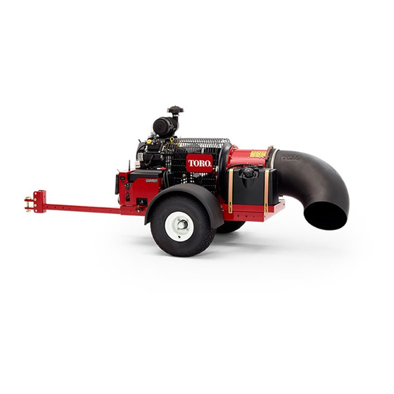
- Page 1 Form No. 3359-689 Rev C Pro Force™ Debris Blower Model No. 44538—Serial No. 280000001 and Up Register at www.Toro.com. Original Instructions (EN)
-
Page 2: Introduction
Whenever you need service, genuine Toro parts, or may have similar laws. additional information, contact an Authorized Service Dealer or Toro Customer Service and have the model Electromagnetic Compatibility and serial numbers of your product ready. Figure 1 Domestic: This device complies with FCC rules Part 15. -
Page 3: Table Of Contents
Contents Introduction..............2 Figure 2 Safety ................4 1. Safety alert symbol Safe Operating Practices ........4 Safety and Instructional Decals ......6 Setup................7 This manual uses 2 other words to highlight information. 1 Remove, Activate and Charge Battery ....8 Important calls attention to special mechanical 2 Install the Battery.......... -
Page 4: Safety
Safety • Use extra care when handling gasoline and other fuels. They are flammable and vapors are explosive. Hazard control and accident prevention are – Use only an approved container dependent upon the awareness, concern, and – Never refuel or drain the machine indoors. proper training of the personnel involved in the –... -
Page 5: Maintenance And Storage
Replace all worn or damaged decals. Maintenance and Storage • Use only Toro approved attachments. Warranty may • Let engine cool before storing and do not store near be voided if used with unapproved attachments. flame. -
Page 6: Safety And Instructional Decals
Safety and Instructional Decals Safety decals and instructions are easily visible to the operator and are located near any area of potential danger. Replace any decal that is damaged or lost. 115-5106 1. Warning—read the Operator’s Manual. 2. Thrown object hazard—keep bystanders a safe distance from the machine. -
Page 7: Setup
Setup Loose Parts Use the chart below to verify that all parts have been shipped. Procedure Description Qty. Electrolyte (not supplied) Charge the battery Petroleum jelly (not supplied) Install the battery Debris blower assembly Hitch Bolt (3/8 x 3 inches) Flange nut (3/8 inch) Mount the hitch to the debris blower Hitch clevis... -
Page 8: Remove, Activate And Charge Battery
2. Remove the strap securing the battery cover to the battery box (Figure 3). Remove, Activate and Charge Battery Parts needed for this procedure: Electrolyte (not supplied) Procedure 1. If the battery is not filled with electrolyte or activated, bulk electrolyte with 1.260 specific gravity must be purchased from a local battery supply outlet and added to the battery. -
Page 9: Install The Battery
Install the Battery Parts needed for this procedure: Petroleum jelly (not supplied) Procedure 1. Slide the battery into the battery box with the terminals toward the engine. Figure 5 1. Electrolyte Important: Do not overfill the battery. Battery terminals or metal tools could short against metal processor components causing Electrolyte will overflow onto other parts of the sparks. -
Page 10: Mounting The Hitch To The Debris Blower
Figure 8 1. Frame brackets 3. Hitch clevis 2. Hitch tube Figure 7 Note: The hitch tube can be rotated 180 degrees to 1. Battery box 4. Positive battery post accommodate different hitch heights. 2. Negative battery post 5. Battery strap 3. -
Page 11: Product Overview
Product Overview • Remove the bolts and nuts securing the hitch tube to frame brackets (Figure 8). • Secure the tube to the frame with the bolts and Controls flange nuts. 4. Connect the blower clevis hitch to the tow vehicle Engine Stop hitch with the hitch pin and clevis (Figure 9). -
Page 12: Choke Control
Choke Control To start a cold engine, move the choke control lever (Figure 11) to the ON position. Figure 11 1. Ignition switch 3. Hour meter 2. Choke control Hour Meter The hour meter (Figure 11) indicates the total hours of machine operation. -
Page 13: Operation
Operation In certain conditions during fueling, static Note: Determine the left and right sides of the electricity can be released causing a spark machine from the normal operating position. which can ignite the gasoline vapors. A fire or explosion from gasoline can burn you and Adding Fuel others and can damage property. -
Page 14: Checking The Engine Oil Level
Important: Do not use fuel additives containing methanol or ethanol. Add the correct amount of gas stabilizer/conditioner to the gas. Note: A fuel stabilizer/conditioner is most effective when mixed with fresh gasoline. To minimize the chance of varnish deposits in the fuel system, use fuel stabilizer at all times. -
Page 15: Controller Time Out
Note: A warm or hot engine may not require • When in the time-out mode the engine will not run choking. After engine starts, move choke control (or will quit running) and the remote transmitter to off position. will not control any function. 3. - Page 16 • Be alert, slow down and use caution when making turns. Look behind and to the side before changing directions. • Be aware of the blower nozzle direction and do not point it at anyone. • Use care when approaching blind corners, shrubs, trees, or other objects that may obscure vision.
-
Page 17: Maintenance
Maintenance Recommended Maintenance Schedule(s) Maintenance Service Maintenance Procedure Interval • Check condition and tension of belt After the first 8 hours • Check the torque of the wheel lug nuts After the first 10 hours • Check the engine oil level. •... -
Page 18: Daily Maintenance Checklist
Daily Maintenance Checklist Duplicate this page for routine use. Maintenance Check Item For the week of: Mon. Tues. Wed. Thurs. Fri. Sat. Sun. Check the instrument operation Check the fuel level. Check the engine oil level. Clean the engine air cooling fins. -
Page 19: Servicing The Air Cleaner
Servicing the Air Cleaner 2. Dry the pre-filter by squeezing it in a clean cloth (do not wring). Service Interval: Every 25 hours—Clean the foam air 3. Put one or two ounces of oil on the pre-filter filter element and check the paper (Figure 15). -
Page 20: Servicing The Engine Oil
Servicing the Engine Oil Note: Change the oil more frequently when the operating conditions are extremely dusty or sandy. Oil Type: Detergent oil (API service SG, SH, SJ or higher) Crankcase Capacity: w/filter, 67 oz. (2 l) Viscosity: See the table below. Figure 18 1. -
Page 21: Synchronize The Remote Transmitter/Control Module
5. Fill the crankcase with the proper type of new oil; refer to Servicing the Engine Oil. 6. Run the engine for about 3 minutes, stop the engine, and check for oil leaks around the oil filter. 7. Check the engine oil level and add oil if needed. Synchronize the Remote Transmitter/Control Module If the remote is ever replaced, it will have to be... -
Page 22: Servicing The Spark Plugs
Servicing the Spark Plugs Ensure that the air gap between the center and side electrodes is correct before installing the spark plug. Use a spark plug wrench for removing and installing the spark plugs and a gapping tool/feeler gauge to check and adjust the air gap. -
Page 23: Servicing The Fuel Tank
Cleaning the Engine Screen and the Oil Cooler Service Interval: Before each use or daily Before each use, check and clean the engine screen and oil cooler. Remove any build up of grass, dirt or other debris from the oil cooler and engine screen (Figure 25). Figure 24 1. -
Page 24: Electrical Maintenance
Fusible Link A fusible link is incorporated into the machines wiring. It is a grey wire located below the in line fuse. Waste Disposal Engine oil, engine and remote batteries are pollutants to the environment. Dispose of these according to your state and local regulations. - Page 25 8. Remove the spark plug(s) and check its condition; refer to Servicing the Spark Plugs. With the spark plug(s) removed from the engine, pour two tablespoons of engine oil into the spark plug hole. Now use the starter to crank the engine and distribute the oil inside the cylinder.
-
Page 26: Schematics
Schematics Electrical Schematic (Rev. -) - Page 27 Notes:...
- Page 28 Countries Other than the United States or Canada Customers who have purchased Toro products exported from the United States or Canada should contact their Toro Distributor (Dealer) to obtain guarantee policies for your country, province, or state. If for any reason you are dissatisfi ed with your Distributor’s service or have diffi...