
Related Manuals for Toshiba FT-8981A


Summary of Contents for Toshiba FT-8981A
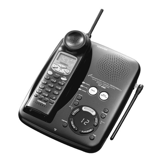
- Page 1 FILE NO. 2BO-200114 SERVICE MANUAL CORDLESS TELEPHONE FT-8981A PUBLISHED IN JAPAN, Oct., 2001...
-
Page 2: Table Of Contents
CONTENTS SAFETY PRECAUTIONS ........................1 OPERATING CONTROLS ........................2 ANSWERING MACHINE ........................3 ALIGNMENT PROCEDURE ........................4 BLOCK DIAGRAMS ..........................8 SCHEMATIC DIAGRAMS ........................10 TROUBLESHOOTING HINTS ......................16 IC AND TRANSISTOR VOLTAGE CHART ..................23 SEMICONDUCTOR LEAD IDENTIFICATION ..................29 ELECTRICAL PARTS LOCATION ...................... -
Page 3: Operating Controls
OPERATING CONTROLS HANDSET CONTROLS AND FUNCTIONS Dot matrix display Antenna Number of calls LCD Display Date Time VOL/RING Button FLASH Button Caller’s telephone number COMPANDOR NOISE REDUCTION REDIAL FLASH Caller’s name REDIAL Button VOL/ RING SELECT Button TALK Button SELECT CID Button L.D. -
Page 4: Answering Machine
ANSWERING MACHINE SETTING THE CLOCK 1. Press twice, then press MENU 2. Select the day of the week by pressing . When the correct day is announced, SELECT SELECT press 3. Select the hour by pressing . When the correct hour is announced, press SELECT SELECT 4. -
Page 5: Alignment Procedure
ALIGNMENT PROCEDURE Base Unit Transmitter Section Connections BASE Unit AF GEN. Test Point Power Meter DC IN TEL Line 1kHz -10.5dBm 9V Jack Jack Test Point Frequency Counter AC 120V Adapter 60Hz Deviation Meter Preset Press and hold the “ANSWER” key about 5.0 seconds while turning the 7. SEG LED shows “8” . Alignment Procedure step Adjustment... - Page 6 Receiver Section Connections BASE Unit AC Voltmeter RF SG Dummy Load (600-ohm) TEL Line Test Point Jack DC Voltmeter DC IN 9V Jack Test Point AC 120V 60Hz Adapter Preset Place the Base Unit in RX SENS mode (step 11) in accordance with the precedure on page 4. Alignment Procedure step Preset to...
- Page 7 Handset Unit Transmitter Section Connections HANDSET Unit AF GEN. Test Point Power Meter J601 Battery 1kHz 9mV MIC+Pin Connector Test Point Frequency Counter DC Power Supply Deviation Meter DC 3.8V Preset a) Connect DC power supply to battery connector on the handset unit. b) Turn the DC power supply on while pressing “...
- Page 8 Receiver Section Connections HANDSET Unit AC Voltmeter RF SG Dummy Load (150-ohm) Connector Test Point DC Power Supply J601 DC Voltmeter Battery Terminal Connector DC 3.8V Preset a) Connect DC power supply to battery connector on the handset unit. b) Turn the DC power supply on while pressing “ ∗ ” and “ # ” keys, and keep pressing the keys continuously for approximate 2 seconds.
-
Page 9: Block Diagrams
BLOCK DIAGRAMS Base Unit — 8 —... - Page 10 Handset Unit — 9 —...
-
Page 11: Schematic Diagrams
SCHEMATIC DIAGRAMS Base Unit RF Section — 10 — — 11 —... - Page 12 Base Key Unit — 12 — — 13 —...
- Page 13 Handset Unit RF Section — 14 — — 15 —...
-
Page 14: Troubleshooting Hints
TROUBLESHOOTING HINTS 1. The bell of base unit does not ring. Set RINGER volume setting Check RINGER mode setting is Hi or Low. to Hi or Low. See 2. The bell does not ring When the PAGE SW of the &... - Page 15 2. The bell of handset does not ring & page does not ring. Can the base and handset be See 3. The base and handset connected? cannot be connected. Press handset DIAL key When the key of the handset is Check IC608.
- Page 16 3. The base and handset cannot be connected. Check whether the base Check IC6 and its is able to set in the test peripheral circuit. mode 8. Check the TX POWER Check base RF section. and the TX FREQUENCY on the base unit. Set the base in the test Check whether there is a Check RT2, R98, R91,...
- Page 17 Set the handset in the Check whether there is a Check R712, R713, R716, test mode 3, check 250 Hz data waveform at R717, R668, C719, C748 whether deviation of the RT602. and RT602. TX data is app. 9.0 kHz Dev.
- Page 18 4. Cannot make a phone call (pulse). Can the base and handset See 3. The base and handset be connected? cannot be connected. While in TALK MODE, press Check IC6. dial key of the handset. Check whether square waveform from Pin 80 of IC6 is fed.
- Page 19 6. Voice cannot be transmitted to other party (outgoing call). Can the base and handset be See 3. The base and handset connected? cannot be connected. The 1 kHz, 9.0mV sine wavefor m i s a p p l i e d t o Check IC602 and its MC601 + side, check peripheral circuit.
- Page 20 7. The voice of the caller cannot be heard (incoming call). Can the base and handset be See 3. The base and handset connected? cannot be connected. The 1 kHz, −10.5dBm Check the base TEL-line sine waveform is applied circuit and RELAY control to TELL-line of the base, circuit.
-
Page 21: Ic And Transistor Voltage Chart
IC AND TRANSISTOR VOLTAGE CHART TRANSISTORS Unit [V] Unit [V] Ref. Ref. STBY Note TALK Note STBY Note TALK Note 2.6/3.3 -3.1/0.6 -3.6/0.8 0-3.6 Q601 Q602 Q603 Q604 Q605 Q608 Q609 Q610 — 23 —... - Page 22 Unit [V] IC's Unit [V] Ref. Ref. STBY Note TALK Note STBY Note TALK Note Q611 Q612 Q613 2.7-3.1 10.1MHz 2.6-3.0 10.1MHz GND(digital) GND(digital) Q614 Q615 0.2-3.2 PLLCLK PLLCLK 0.2-3.2 PLLDATA PLLDATA Q616 0.2-3.2 PLLENB PLLENB 3.5-0.0 DATA(PULSE) 3.5-0.0 DATA(PULSE) —...
- Page 23 IC's Unit [V] Unit [V] Ref. Ref. STBY Note TALK Note STBY Note TALK Note 3.9-2.5 X'TAL 3.9-2.5 X'TAL 3.1-2.3 X'TAL 3.1-2.3 X'TAL 2.4-2.0 COL00 COL00 COL01 COL01 3.4-3.2 3.4-3.2 COL02 COL02 COL03 COL03 COL04 COL04 2.1-0.8 INUSE_LED INUSE_LED ROW00 ROW00 ROW01 ROW01...
- Page 24 Unit [V] Unit [V] Ref. Ref. STBY Note TALK Note STBY Note TALK Note AGND AGND ANS LED(ANS on) ANS LED(ANS on) Vref Vref CHARGE LED CHARGE LED PLLGND PLLGND PLLVcc PLLVcc PLLVcc PLLVcc 1.1-0.0 X'TAL 1.1-0.0 X'TAL 1.4-0.0 X'TAL 1.4-0.0 X'TAL DGND...
- Page 25 Unit [V] Unit [V] Ref. Ref. STBY Note TALK Note STBY Note TALK Note 2.9-0.0 DATA(PULSE) 3.0-0.1 DATA(PULSE) OPEN OPEN OPEN OPEN GND(digital) GND(digital) OPEN OPEN GND(digital) GND(digital) IC602 OPEN OPEN GND(digital) GND(digital) OPEN OPEN GND(digital) GND(digital) GND(digital) GND(digital) GND(digital) GND(digital) 1.7-0.4 1.7-0.5...
- Page 26 Unit [V] Ref. STBY Note TALK Note IC608 — 28 —...
-
Page 27: Semiconductor Lead Identification
SEMICONDUCTOR LEAD IDENTIFICATION DIODES 1N4148 SML-310LT HVC355B HZ33-2 HZK6C HZ33CP SML-310MT HZ4B1 Anode HZ6B2 HZ6C3 Cathode Anode Anode Cathode Anode Cathode HZ11A Cathode 1SS226 ISS294 EMPG4868K MM4148 LTD-482P Cathode Anode/Cathode Anode Cathode 16 15 14 13 12 11 10 9 DIGIT 1 DIGIT 2 Anode... - Page 28 K9F4008WOA D16559 CD11 CD12 N.C. N.C. CD13 N.C. N.C. CD14 CD15 N.C. N.C. CA10 N.C. N.C. CA11 N.C. N.C. GPIO15 CA12 N.C. N.C. GPIO14 CA13 GPIO13 CA14 N.C. N.C. GPIO12 CA15 N.C. N.C. GPIO11 N.C. N.C. GPIO10 N.C. N.C. GPIO9 RASN N.C.
-
Page 29: Electrical Parts Location
ELECTRICAL PARTS LOCATION Base Unit Main PCB — 31 —... - Page 30 Base Unit Key PCB — 32 —...
- Page 31 Handset Unit Main PCB — 33 —...
-
Page 32: Wiring Diagrams
WIRING DIAGRAMS Base Unit — 34 —... - Page 33 Handset Unit — 35 —...
-
Page 34: Exploded View And Mechanical Parts List
EXPLODED VIEW AND MECHANICAL PARTS LIST HANDSET MAIN PCB ASSY BASE MAIN PCB ASSY SP751 SP801 BASE KEY PCB ASSY AT751 — 36 —... - Page 35 LOC. PART NO. REF NO. DESCRIPTION RC009896 GNBZ366565Z BUTTON, FUNCTION RC009557 GNBZ447715Z BUTTON, FUNCTION RC009897 GNBZ467967Z BUTTON, FUNCTION RC009898 GNBZ467968Z BUTTON, PUSH PMMA RC012320 GCAS274455Z CASE, BOTTOM RC009914 GCAS266566Z CASE, TOP RC009325 HTML446079Z CHARGE TERMINAL C5191(PBP) RC009396 GCAS346381Z DISPLAY WINDOW PMMA RC009837 LFUT494200Z...
-
Page 36: Parts List
PARTS LIST PRODUCT SAFETY NOTE: Products marked with a have special characteristics important to safety. Before replacing any of these components, read carefully the product safety notice of this service manual. Don’ t degrade the safety of the product through important servicing. Symbol Symbol ±1... - Page 37 LOC. PART NO. REF NO. DESCRIPTION RC008062 BCMM817092Z CERAMIC M/L 7PF 50V D CH RC005205 BCML811035Z CERAMIC M/L 0.01UF 50V K B RC005360 BCMM816092Z CERAMIC M/L 6PF 50V D CH RC005222 BCMS811091Z CERAMIC M/L 1PF 50V C CK RC005223 BCMS812091Z CERAMIC M/L 2PF 50V C CK RC005202...
- Page 38 LOC. PART NO. REF NO. DESCRIPTION RC005205 BCML811035Z CERAMIC M/L 0.01UF 50V K B RC001806 BCAZ812286Z ELECTROLYTIC 0.22UF 50V M C-156 RC005202 BCML311045Z CERAMIC M/L 0.1UF 16V K B RC005202 BCML311045Z CERAMIC M/L 0.1UF 16V K B C100 RC005420 BCMM811514Z CERAMIC M/L 150PF 50V J CH C101...
- Page 39 LOC. PART NO. REF NO. DESCRIPTION C155 RC005216 BCMM813304Z CERAMIC M/L 33PF 50V J CH C156 RC005216 BCMM813304Z CERAMIC M/L 33PF 50V J CH C157 RC005216 BCMM813304Z CERAMIC M/L 33PF 50V J CH C158 RC005216 BCMM813304Z CERAMIC M/L 33PF 50V J CH C159 RC005205 BCML811035Z...
- Page 40 LOC. PART NO. REF NO. DESCRIPTION C601 RC005224 BCMT813091Z CERAMIC M/L 3PF 50V C CJ C602 RC005216 BCMM813304Z CERAMIC M/L 33PF 50V J CH C603 RC008062 BCMM817092Z CERAMIC M/L 7PF 50V D CH C604 RC005223 BCMS812091Z CERAMIC M/L 2PF 50V C CK C605 RC005216 BCMM813304Z...
- Page 41 LOC. PART NO. REF NO. DESCRIPTION C659 RC005223 BCMS812091Z CERAMIC M/L 2PF 50V C CK C660 RC005215 BCMM812704Z CERAMIC M/L 27PF 50V J CH C661 RC005205 BCML811035Z CERAMIC M/L 0.01UF 50V K B C662 RC005207 BCML813325Z CERAMIC M/L 0.0033UF 50V K B C663 RC004412 BCXT312245Z...
- Page 42 LOC. PART NO. REF NO. DESCRIPTION C716 RC005202 BCML311045Z CERAMIC M/L 0.1UF 16V K B C717 RC008731 BCXK311050Z CERAMIC M/L (2125) 1UF 16V Z F C718 RC008731 BCXK311050Z CERAMIC M/L (2125) 1UF 16V Z F C719 RC008731 BCXK311050Z CERAMIC M/L (2125) 1UF 16V Z F C720 RC005205...
- Page 43 LOC. PART NO. REF NO. DESCRIPTION RC002236 BDAY0246003 AX TS 26+ 1N4148 T-77 RC003194 BDAY0272010 ZENER HZ33CP RC002236 BDAY0246003 AX TS 26+ 1N4148 T-77 RC002236 BDAY0246003 AX TS 26+ 1N4148 T-77 RC002471 BDAY0492045 ZENER AX TS 26+ HZ6C3 TD RC002471 BDAY0492045 ZENER AX TS 26+ HZ6C3 TD...
- Page 44 LOC. PART NO. REF NO. DESCRIPTION RC004774 BDEY2957001 LTV-817 CD RC009040 BDEY3493003 TK11237BMCL RC009378 BDEY3965003 XC612N4540MR IC601 RC008298 BDEY3869003 M64884FP-C60J IC602 RC009438 BDEY3972003 LA8634VU-TLM IC603 RC009855 BDEY3871003 KA3361CDTF IC605 RC008859 BDEY2927003 RH5RE32AA-T1 IC606 RC008323 BDEY3886003 XC612N3328MR IC607 RC009807 BDEY4114003 NJM2870F03(TE1) IC608 RC009913 BDDY1206001...
- Page 45 LOC. PART NO. REF NO. DESCRIPTION L615 RC008281 BLBY1175001 COIL LB-1175 7002BE-A0026HM L616 RC009749 BLZY0218476 INDUCTOR MOLDED CHIP LZ-218 CIH10T4N7S T 4.7NH RC003234 BTFY0265001 TRANSFORMER HYBRID TF-265 AT-24E7-1B(295403) TRANSISTORS RC009280 BDBZ1135001 DB-1135 MT4S06U(TE85L) RC008760 BDBC5065124 DB-848 2SC5065-Y(TE85R) RC012040 BDBC3052106 DB-862 2SC3052-T12-1F RC008760 BDBC5065124 DB-848 2SC5065-Y(TE85R)
- Page 46 LOC. PART NO. REF NO. DESCRIPTION RC005311 BRFC160004Z CARBON FIXED CHIP 0 1/16W J RC005247 BRFC162214Z CARBON FIXED CHIP 220 1/16W J RC005434 BRFC163914Z CARBON FIXED CHIP 390 1/16W J RC005284 BRFC163334Z CARBON FIXED CHIP 33K 1/16W J RC005241 BRFC161034Z CARBON FIXED CHIP 10K 1/16W J RC008767...
- Page 47 LOC. PART NO. REF NO. DESCRIPTION RC005240 BRFC161024Z CARBON FIXED CHIP 1K 1/16W J RC005250 BRFC162704Z CARBON FIXED CHIP 27 1/16W J RC005260 BRFC166834Z CARBON FIXED CHIP 68K 1/16W J RC005288 BRFC168244Z CARBON FIXED CHIP 820K 1/16W J RC005245 BRFC161834Z CARBON FIXED CHIP 18K 1/16W J RC005239...
- Page 48 LOC. PART NO. REF NO. DESCRIPTION R125 RC005240 BRFC161024Z CARBON FIXED CHIP 1K 1/16W J R126 RC005240 BRFC161024Z CARBON FIXED CHIP 1K 1/16W J R127 RC005240 BRFC161024Z CARBON FIXED CHIP 1K 1/16W J R128 RC005247 BRFC162214Z CARBON FIXED CHIP 220 1/16W J R129 RC005240 BRFC161024Z...
- Page 49 LOC. PART NO. REF NO. DESCRIPTION R184 RC005673 BRFC163934Z CARBON FIXED CHIP 39K 1/16W J R186 RC005311 BRFC160004Z CARBON FIXED CHIP 0 1/16W J R187 RC005239 BRFC161014Z CARBON FIXED CHIP 100 1/16W J R188 RC005252 BRFC163314Z CARBON FIXED CHIP 330 1/16W J R189 RC005252 BRFC163314Z...
- Page 50 LOC. PART NO. REF NO. DESCRIPTION R245 RC005242 BRFC161044Z CARBON FIXED CHIP 100K 1/16W J R246 RC005240 BRFC161024Z CARBON FIXED CHIP 1K 1/16W J R247 RC005242 BRFC161044Z CARBON FIXED CHIP 100K 1/16W J R248 RC005240 BRFC161024Z CARBON FIXED CHIP 1K 1/16W J R249 RC005242 BRFC161044Z...
- Page 51 LOC. PART NO. REF NO. DESCRIPTION R633 RC005240 BRFC161024Z CARBON FIXED CHIP 1K 1/16W J R634 RC005240 BRFC161024Z CARBON FIXED CHIP 1K 1/16W J R635 RC008765 BRFC161004Z CARBON FIXED CHIP 10 1/16W J R636 RC005240 BRFC161024Z CARBON FIXED CHIP 1K 1/16W J R637 RC005256 BRFC164724Z...
- Page 52 LOC. PART NO. REF NO. DESCRIPTION R701 RC005260 BRFC166834Z CARBON FIXED CHIP 68K 1/16W J R702 RC005260 BRFC166834Z CARBON FIXED CHIP 68K 1/16W J R703 RC005256 BRFC164724Z CARBON FIXED CHIP 4.7K 1/16W J R704 RC005262 BRFC168234Z CARBON FIXED CHIP 82K 1/16W J R705 RC008765 BRFC161004Z...
- Page 53 LOC. PART NO. REF NO. DESCRIPTION RC012107 BRTY0552203 SEMI-FIXED RT-552 20KB RT601 RC012289 BRTY0569222 SEMI-FIXED RT-569 PVZ3A222A01R00 RT602 RC008327 BRTY0569223 SEMI-FIXED RT-569 PVZ3A223A01R00 RT603 RC008328 BRTY0569224 SEMI-FIXED RT-569 PVZ3A224A01R00 RT604 RC008327 BRTY0569223 SEMI-FIXED RT-569 PVZ3A223A01R00 CRYSTALS RC008478 BQXY0724001 QX-724 10.1MHZ RC009888 BQXY0760001 QX-760 3.968MHZ...
-
Page 54: Assembly Parts List
ASSEMBLY PARTS LIST NOTE: Following part numbers are not available as replacement parts. Order parts necessary for repair or contact the Toshiba Factory Service Center. LOC. PART NO. REF NO. DESCRIPTION RC012324 AC340BHBA MAIN PCB ASSY, BASE RC012310 AC339BHBB KEY PCB ASSY, BASE... -
Page 55: Specifications
SPECIFICATIONS MEASUREMENT CONDITIONS 1. Standard Voltage: DC 3.8 V ±0.025 V Portable Unit AC 120 V ±3 V 60 Hz Base Unit 25 °C ±5 °C 2. Temperature: 3. Channel: Portable (TX Frequency) Base (TX Frequency) 904.052470 MHz 925.997470 MHz 902.102465 MHz 926.047470 MHz 902.152465 MHz... - Page 56 BASE UNIT RECEIVER Unit Nominal Limit −115 < −107 1. Sensitivity 12 dB SINAD (with CCITT Filter) 2. Frequency Response (Ref: 1 kHz) −4.0 ~ +4.0 0.3 kHz −2.0 −6.0 ~ +2.0 3.0 kHz 3. Distortion at 1 mV RF Input <...
- Page 57 HANDSET UNIT RECEIVER Unit Nominal Limit −115 1. Sensitivity 12 dB SINAD (with CCITT Filter) <−107 2. AF Frequency Response (Ref: 1 kHz at 5 kHz Dev) 0.3 kHz +5.5 +1.5 ~ +9.5 −10.0 −14.0 ~ −6.0 3.0 kHz LOW +15.5 ±3 3.
- Page 58 FSK SENSITIVITY (ON HOOK) −44.0 1. Minimum Acceptable Signal Level: <−36.0 (with 25dB S/N ratio) −12< 2. Maximum Acceptable Signal Level: (with 25dB S/N ratio) OTHERS Ni-Cd Battery 600 mAH (@1.2 V × 3 = 3.6 V) 1. Battery: 2. Memory: 10 Memories (NAME : 14 Digits, Number : 20 Digits) + 1 Redial Memory (32 Digits) + 20CID Memories (NAME : 15 Digits, Number : 15 Digits)
- Page 59 TOSHIBA AMERICA CONSUMER PRODUCTS, INC. 82 TOTOWA ROAD, WAYNE, N.J. 07470 TOSHIBA HAWAII, INC. 327 KAMAKEE ST., HONOLULU, H.I. 96814...