Table of Contents
Advertisement
Advertisement
Table of Contents

Related Manuals for Sony MCS-8M


Summary of Contents for Sony MCS-8M
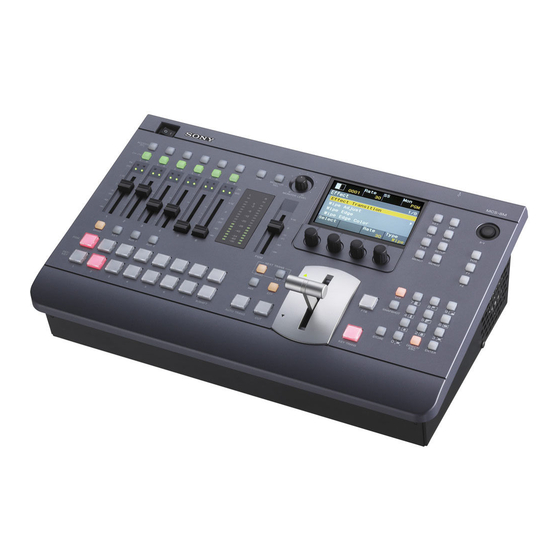
- Page 1 4-296-436-12 (1) Multi Format Compact Switcher Operating Instructions (Volume II Advanced Settings) Before operating the unit, please read this manual thoroughly and retain it for future reference. MCS-8M Software Version 1.03 or later © 2011 Sony Corporation...
-
Page 2: Table Of Contents
Chapter 3 Audio Mixing Table of Contents Overview ................II-31 (this manual) Details on [Audio Channel] Menu ......II-31 Chapter 1 Overview Chapter 4 Input Image Freezing and Frame Memory Introduction............... II-5 System Configuration Examples ..........II-5 Overview ................II-34 Freezing Input Images..........II-34 Chapter 2 Video Switching Selecting Frame Memory for Use as Frame Memory Overview ................ - Page 3 Chapter 8 Setup ([Setup] Menu) Table of Contents Overview ................II-48 (Volume I Basic Operation) System Setup (System)..........II-48 Details on [System] Menu ............II-49 Chapter 1 Overview Audio Setup (Audio) ............. II-50 Details on [Audio] Menu............II-50 Introduction Video Input Setup (Video (Input))......II-52 Names and Functions of Parts Details on [Video (Input)] Menu ..........II-52 Assigning Video Input Signals to the Cross Point...
-
Page 4: About This Manual
About This Manual This manual describes how to make adjustments and settings to enable you to use the advanced features of this unit. For the basic operating procedures of the unit, see to “Operating Instructions (Volume I Basic Operation).” How to View This Manual About setting values The setting values shown in bold are the factory default settings. -
Page 5: Chapter 1 Overview
Overview Chapter Introduction The unit allows you to adjust and set video effects, transitions, and audio in detail to perform more sophisticated switching. You can also perform 3D video switching, and use the frame memory function to write one screen of the input video to memory so that you can use it as input material. - Page 6 Example 2: When 3D system Presenter Host microphone microphone MIC/LINE MIC/LINE Right camera Left camera CD/DVD player HD SDI Multi Viewer display HD SDI (R) LINE Right camera Left camera DVI-D DVI⇔HDMI HD SDI conversion cable HD SDI (R) Headphones HD SDI HD SDI (L+R) PGM monitoring display...
-
Page 7: Overview
Video Switching Chapter Overview This unit includes three video composition blocks: M/E (Mix/Effect), Aux1, and Aux2. You can also apply transitions between the buses of each block. Video input Video output PGM Bus Preview PST Bus (Mix/Effect) Key Fill Bus Program Key Source Bus Aux1 Preview... -
Page 8: Setting The Transition Type
For the first half of the transition, the current image is Setting the Transition maintained at 100% and NAM is gradually performed for the new image. At the halfway point, NAM is Type performed for both images which are maintained at 100%. -
Page 9: Aux Mixing
AUX Mixing You can switch video via mixing (AUX Mixing) in the Aux blocks of this unit. In addition, you can select the M/E program output as the input signal in the Aux blocks, allowing you to switch the video composed in the M/E block with another video via mixing in the Aux blocks and simulate the flexible video composition of a 2M/E switcher. -
Page 10: Setting Wipes
Selecting the Pattern and Direction Setting Wipes for Wipes A wipe can be set to proceed in either the normal wipe A wipe is a transition effect that switches to the next video direction (normal) or reverse wipe direction (reverse). You by applying an effect that removes the program output can also specify normal and reverse to be switched each video in a manner that appears as it is being wiped off with... - Page 11 Setting the wipe position Settings menu: [Wipe Modify] menu > [Rotation] (page II-17), [Rotation Adjust] (page II-17) The wipe position can be set in the [Wipe Modify] menu or with the X-Y pointer in the menu control block. Setting the aspect ratio of a wipe pattern You can freely change the aspect ratio of a wipe pattern.
-
Page 12: Adding The Edge To The Wipe Pattern
Adding the Edge to the Wipe Pattern Setting DME Wipes You can add a border around the pattern (border), defocus the edge around the pattern (soft), and defocus an added DME wipes are effects that use DME (digital multi effects) edge of border (soft border). -
Page 13: Making Detailed Adjustments To Dme Wipe Patterns
The cropping process when the transition is executed is as Making Detailed Adjustments to follows. DME Wipe Patterns Transition You can adjust the position of a DME wipe pattern, adjust Crop the size of the sub-screen for during PinP, perform cropping to cut the edge of the image, and make other settings in the [DME Wipe Modify] menu. -
Page 14: Adding An Edge To A Dme Wipe Pattern
Adding an Edge to a DME Wipe Pattern With a DME wipe, you can add a border around the pattern (border) and defocus the edge of an added border (soft border). The edge color and background color can also be adjusted. For details on how to add an edge, see “Adding the Edge to the Wipe Pattern”... -
Page 15: Details On [Effect] Menu
Details on [Effect] Menu [Effect] Menu Press the EFF button in the menu control block to display the [Effect] menu. Menu item Description Knob Parameter Meaning Setting range Reference page Effect Set the transition rate and transition type Rate Transition rate 1 to 999 frames II-8 Transition... -
Page 16: [Wipe Modify] Menu
Menu item Description Knob Parameter Meaning Setting range Reference page DME Wipe Add a border around the DME pattern Type DME wipe edge Off, Border, II-14 Edge (border), and defocus the edge of an type S-Brdr (soft added border (soft border). border) Width Adjusts border... - Page 17 Menu item Description Knob Parameter Meaning Setting range Reference page Rotation Set the rotation method of a wipe pattern. V4 Rotate Rotation type Off, Angle, II-11 Speed, Mag (magnitude) Rotation Set the parameters depending on the Angle • Pattern –100.00 to II-11 Adjust rotation type selected in [Rotation].
-
Page 18: [Dme Wipe Modify] Menu
[DME Wipe Modify] Menu Display the [DME Wipe Modify] menu by pressing the V1 knob while [DME Wipe Adjust] is selected. Menu item Description Knob Parameter Meaning Setting range Reference page Positioner Turn the positioner for adjusting the Turns positioner Off, On II-13 DME wipe position on/off. -
Page 19: Setting Keys
Basic Operations for Keys Setting Keys Use the following procedure to perform basic operations for keys. A key is a function for cutting out the background image Material selection and then inserting an image or text in that portion. The signal for cutting out the background is called a key source, the signal for filling the cutout portion is called a Transition configuration... -
Page 20: Setting Key Transitions
Transition execution Selecting the Pattern and Direction for Key Wipes Execute the transition using the fader lever, CUT button, or AUTO TRANS button. You can cut out the background from a wipe pattern selected for a key transition and then embed a key. Key transition Settings menu: [Key Wipe Modify] (page II-24) Material selection... -
Page 21: Making Detailed Adjustments To Key Dme Wipe Patterns
Making Detailed Adjustments to Key Making Detailed Adjustments to the DME Wipe Patterns Linear Key You can adjust the position of a key DME wipe pattern and You can make detailed adjustments for the cutout adjust the size of a sub-screen for during Frame In/Out and condition of the background, the key density, and other PinP in the [Key DME Wipe Modify] menu. -
Page 22: Setting A Mask For A Key
The key fill and key source pairs selected when [Auto] Setting modifiers for the key edge is selected are as follows. Turn drop mode on or off and set the type of modifier. • If you turn drop mode on, the position of the key fill and Key fill Key source key source will move downward, regardless of whether... -
Page 23: Details On [Key] Menu
Details on [Key] Menu [Key] Menu Press the KEY button in the menu control block to display the [Key] menu. Menu item Description Knob Parameter Meaning Setting range Reference page Set the transition rate and transition type Rate Transition rate 1 to 999 (30) II-20 Transition... - Page 24 Menu item Description Knob Parameter Meaning Setting range Reference page Lin Key Adjust the linear key density. Dens Key density 0 to 100.00 – Adjust (2/2) Lin Key Turn the clean mode for the linear key on/ Clean Turns clean Off, On –...
- Page 25 Menu item Description Knob Parameter Meaning Setting range Reference page Key Mask Set the key mask function for masking a Mask Turns mask Off, On II-22 portion of a key signal. function on/off Invert On/off of mask Off, On inversion Key Mask Specify the left and right positions of the Left...
-
Page 26: [Resizer] Menu
[Resizer] Menu Display the [Resizer] menu by pressing the V1 knob while [Resizer] (page II-23) is selected. Menu item Description Knob Parameter Meaning Setting range Reference page Rotation Select whether the resizer function Axis Selects rotation X, Y – Mode moves in 2D or 3D. -
Page 27: [Auto Chromakey] Menu
Menu item Description Knob Parameter Meaning Setting range Reference page Rotation Rotate the key and adjust perspective. Rot X Amount of • When [Rotation – X-axis rotation Mode] is [Off], fixed at 0.00 (adjustment is disabled) • When [Rotation Mode] is [On], –100.00 to +100.00 (0.00) Rot Y... -
Page 28: [Manual Chromakey] Menu
[Manual Chromakey] Menu Display the [Manual Chromakey] menu by pressing the V1 knob while [Chromakey Manual Adj] (page II-24) is selected. Menu item Description Knob Parameter Meaning Setting range Reference page Chr Key Adjust the background cutout condition, Hue of color you 359.99 to 0.00 –... -
Page 29: [Key Wipe Modify] Menu
[Key Wipe Modify] Menu Display the [Key Wipe Modify] menu by pressing the V1 knob while [Key Wipe] (page II-24) is selected. Menu item Description Knob Parameter Meaning Setting range Reference page Positioner Turn the positioner for adjusting the key AutoCT Turns auto Off, On... -
Page 30: [Key Dme Wipe Modify] Menu
Menu item Description Knob Parameter Meaning Setting range Reference page Aspect Change the aspect ratio of a key wipe Aspect Turns aspect Off, On II-11 pattern. Setting the aspect ratio to a adjustment on/ negative value stretches the pattern vertically to make it longer in the vertical Ratio Adjusts aspect –100.00 to +100.00... -
Page 31: Chapter 3 Audio Mixing
Audio Mixing Chapter Overview You can adjust the audio input in detail, set the audio levels, and specify the connectors to use for audio output for each audio channel. Adjust and set the audio from the [Audio Channel] menu for each audio channel. To display the [Audio Channel] menu Press the ACCESS/PFL button in the same column as the channel fader assigned to the audio channel you want to adjust. - Page 32 Menu item Description Knob Parameter Meaning Setting range Reference page Equalizer Use the equalizer function to adjust the EQ H Turns audio Off, On – High audio quality by setting the quality high-frequency band. adjustment of high-frequency band on/off Freq Center frequency 1.30 k to of high-frequency...
- Page 33 Menu item Description Knob Parameter Meaning Setting range Reference page PGM Assign Output the audio from the PGM OUT Turns output of Off, On – Connector. the PGM OUT connector on/off The output level of the audio output from the PGM OUT connector can be adjusted with the program fader in the audio control block.
-
Page 34: Chapter 4 Input Image Freezing And Frame Memory
Input Image Freezing and Frame Memory Chapter Overview Freezing Input Images Input freeze is a function that allows you to freeze images Press the FM button in the menu control block to from individual input signals. display the [Frame Memory] menu, and turn the V1 knob to select [Input Freeze]. -
Page 35: Selecting Frame Memory For Use As Frame Memory Video (Fm
Selecting Frame Memory Saving Images to Frame for Use as Frame Memory Memory Video (FM) Select the frame memory to which to save (Frame Memory 1 to 12), select the input signal to be used as the source, and Display the [Frame Memory] menu, turn the V1 knob to then freeze the input image to write it to memory. -
Page 36: Importing And Exporting Images
USB flash drive, and then insert the USB press a menu selection button. flash drive into the USB connector of the unit. Folder name: \Sony\MCS\FM Delete files one at a time. Multiple files cannot be deleted simultaneously. - Page 37 • Only BMP format files can be exported. Alpha channels cannot be added. • The folder to which the files are exported and the file names are as shown below. Folder name: \Sony\MCS\FM File name: YYMMDD-HHMMSS-##V.bmp (# is the frame memory number [01 to 12]) II-37...
-
Page 38: Chapter 5 Importing And Exporting Files
The folder to which the files are exported is as shown below. Folder name: Miscellaneous \Sony\MCS\CONFIG\YYMMDD-HHMMSS • Frame memory video • Make sure that the number of files in the folder does not exceed 99. Even if a folder contains 100 files or more, only 99 files will be displayed in the list. -
Page 39: Importing Configuration Data
1 to 20 snapshots to export The folder to which the files are exported and the file names are as shown below. Folder name: \Sony\MCS\SNAPSHOT File name: YYMMDD-HHMMSS-##.SSS (## is the snapshot number [01 to 20]) Note When exporting snapshots, make sure that the number of files in the folder does not exceed 99. -
Page 40: Importing Snapshots
The following folders are created when formatting is performed. Turn the V1 knob to select the snapshot to import, turn Folder name:\Sony\MCS\CONFIG each knob to specify the snapshots to import, and press \Sony\MCS\FM the V4 knob to start importing. -
Page 41: Overview
The following restrictions apply when configuring a 3D system including the unit. • Configure the 3D system with only one MCS-8M unit. Two units cannot be used linked together. • When the unit is operated in a 3D system, only an HD (1080i/59.94, 1080i/50, 720p/59.94, or 720p/50) signal... -
Page 42: Making The Necessary Settings
Turning 3D Mode On Making the Necessary Settings Display the [Setup] menu, select [System] menu > [3D Mode], turn the V4 knob to select [On]. Knob Parameter Meaning Setting Make the settings for operating the unit in a 3D system in Value the [Setup] menu. -
Page 43: Confirming 3D Video Output
[File] menu Menu item Restriction Import • Movement to the sub-level setting is Snapshot disabled. Export • Exporting is disabled. Snapshot • The following data will not be saved by the [Startup Define] operation in the [Setup] menu. These settings will return to default values at each startup. -
Page 44: Chapter 7 Controlling External Devices
Controlling External Devices Chapter Setting GPI Inputs Enabling/Disabling Set the operation and trigger type of the GPI input Operation from External contacts. Devices Settings menu: [Setup] menu > [GPI/Tally] menu > [GPI Input 1] to [GPI Input 4] (page II-45) Enable or disable the GPI port which is used for operation You can select from the following operations. -
Page 45: Details On [Gpi/Tally] Menu
Fall: The trigger causes the output to decrease to a high level, and that status will continue for a certain duration (1 to 2 frames). Any: Every time the trigger is activated, the output’s high and low levels change alternately. If the GPI outputs are used as tallies, the relationship between Tally 1 to 8 and the input signals is as follows. - Page 46 Menu item Description Knob Parameter Meaning Setting range Reference page GPI Input 4 Set the operation and trigger type of the Action Contact NotUse, CT, AT, II-44 GPI input 4 contacts. operation KeyCT, KeyAT, Aux1CT, Aux1AT, Aux2CT, Aux2AT, SS1 to SS20 Edge Trigger type...
- Page 47 Menu item Description Knob Parameter Meaning Setting range Reference page Set GPI Output 5 or Tally 5. Selects whether Tally, GPIOut II-44 Output/ to use as tally or (GPI output) Tally 5 GPI output Action Operation when NotUse, CT, AT, used as GPI KeyCT, KeyAT, output...
-
Page 48: Chapter 8 Setup ([Setup] Menu)
Setup ([Setup] Menu) Chapter Overview System Setup (System) Set up the overall system in the [Setup] menu. Make system related settings in the items of the [Setup] menu > [System] menu. The [Setup] menu contains the following items. Supported input reference signals Menu item Description Reference... -
Page 49: Details On [System] Menu
Details on [System] Menu Menu item Description Knob Parameter Meaning Setting range Confirmation (press knob) System Set the format and aspect ratio to be Format Signal format 108059, Necessary Format used by the unit. 108050, (c Basic Operation: “Configuring the 720p59, Signal Format and Aspect Ratio”) 720p50,... -
Page 50: Audio Setup (Audio
Audio Setup (Audio) Assign audio signal inputs to channel faders and make audio related settings in the items of the [Setup] menu > [Audio] menu. SDI output embedded audio and audio signal combinations The following table shows the possible combinations for output. Embedded Audio Possible Combinations for Output SDI 1 to 4 (L) - Page 51 Menu item Description Knob Parameter Meaning Setting range SDI OUT Assign the audio signals output from PGM OUT/MIX Left Audio signal to None, AUX1, AUX1 OUT/AUX OUT 1/AUX OUT 2 connectors to the assign AUX2, PGM-L, Assign embedded audio output from the AUX 1 connector of MIX-L SDI OUT.
-
Page 52: Video Input Setup (Video (Input))
Video Input Setup (Video (Input)) Make video input related settings in the items of the [Setup] menu > [Video (Input)] menu. About DVI input signals • Set the resolution of the DVI signal to be input to one of the following in accordance with the setting of the signal format of the unit (page II-49). -
Page 53: Assigning Video Input Signals To The Cross Point Buttons (Video (Xpt
Shift button function: Off (non-shift mode) Assigning Video Input Signals to the Cross Point Buttons (Video (XPT)) Shift button function: On (shift mode) Assign video signals to the cross point buttons (PGM buttons and PST/KEY buttons) in the items of the [Setup] menu >... -
Page 54: Video Output Setup (Video (Output))
Video Output Setup (Video (Output)) Set the video output signal to assign to each video output connector in the items of the [Setup] menu > [Video (Output)] menu. In 3D mode, this menu is not displayed. Details on [Video (Output)] Menu Menu item Description Knob Parameter Meaning Setting range... -
Page 55: Setup Of Other Video Related Items (Video (Misc
If you turn off the unit before application software update is complete normally, the unit may not start properly. In such cases, contact your local Sony representative. II-55 Setup of Other Video Related Items (Video (Misc)) / Displaying Various Information (Information) / Installing Application Software and Firmware (Install) -
Page 56: Appendix
The internal temperature of the system is high. Turn off the unit Please turn off the system immediately. immediately, and contact your local Sony representative. 4003 Unable to start. Try restarting the unit. If it does not restart, contact your local Sony Please restart. representative. 4004 Unable to start. -
Page 57: Warnings
Message Solution 4203 USB memory is not recognized. Check whether operation has been verified with the respective USB Confirm the USB memory. flash drive model. If operation has been verified, the USB flash drive may be damaged. 4204 Formatting USB memory error. Please retry. -
Page 58: Information
M: xx/B: xx/F: xx/R: xx/Font: xx software and firmware is complete. FPGA1: xx/2: xx/3: xx/4: xx If “E” (error) appears, try installing again. If the problem persists, M: Main contact your local Sony representative. B: Boot F: Firmware R: Register Font: Font •... -
Page 59: Index
AUX 1 Buttons I-12 DME Wipe Adjust II-15 Index AUX 2 Buttons I-12 DME Wipe Bkgd Color II-16 AUX OUT Assign II-33 DME Wipe Edge II-16 AV Link I-24 DME Wipe Edge Color II-16 DME Wipe Modify Menu II-18 Numerics Crop H II-18 3D Mode II-42, II-49 Crop V II-18... - Page 60 Import Config II-39 Key DME Wipe II-24 Limiter II-32 Import Snapshot II-40 Key DME Wipe Modify Menu II-30 Limiter/Compressor II-32 USB Memory Format II-40 Positioner II-30 Lin Key Adjust II-23 Fine Key II-25 Positioner Adjust II-30 Lin Key Mode II-24 Fine Key Adjust H II-25 Size II-30 Linear Key I-32, II-21...
- Page 61 Non-Additive Mix II-8 Setup II-48 Transition Type Selection Button Numeric Buttons (0 to 9) I-13, I-31 SETUP Button I-13 Numeric Keypad I-31 I-11, I-19, I-20, I-21, I-22, II-48 EFF Button Numeric Keypad Block I-13 Setup Menu I-13, I-33, I-34, II-10, II-19 II-45, II-48, II-50, II-52, II-53, MIX Button II-54, II-55...
- Page 62 Rotation II-17 Rotation Adjust II-17 Wipe Patterns II-10 XPT Assign I-21, II-53 XPT Shift Mode II-53 X-Y Pointer I-11, II-11, II-13 II-62 Index...
- Page 63 The material contained in this manual consists of Trademarks information that is the property of Sony Corporation and is HDMI, the HDMI logo, and High-Definition Multimedia intended solely for use by the purchasers of the equipment Interface are registered trademarks or trademarks of described in this manual.
- Page 64 Sony Corporation...