
Related Manuals for Sony CA-TX70


Summary of Contents for Sony CA-TX70
-
Page 1: Operating Instructions
4-452-968-01 (1) HD Camera Adaptor Operating Instructions Before operating the unit, please read this manual thoroughly and retain it for future reference. CA-TX70 © 2012 Sony Corporation... - Page 2 Operation of this This product has been manufactured by equipment in a residential area is likely or on behalf of Sony Corporation, 1-7-1 to cause harmful interference in which Konan Minato-ku Tokyo, 108-0075 case the user will be required to correct Japan.
-
Page 3: Table Of Contents
Table of Contents Overview ............... 4 Features ................ 4 Names and Functions of Parts ........5 System Configuration ..........9 Preparation and Setting ..........10 Attaching the Adaptor to a Camera/Camcorder ..10 Connecting a Camera Control Unit (CCU) ....11 Attaching the Accessory Shoe Kit ...... -
Page 4: Overview
Overview Features The CA-TX70 HD Camera Adaptor is a Cable-free connection to camera/ camera adaptor that allows for long camcorder distance transmission of input and The adaptor can be installed on the output signals via a triax cable, and attachment shoe of a camera/... -
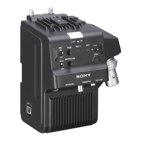
Page 5: Names And Functions Of Parts
Names and Functions of Parts Front 1 Cable clamp attachment 2 TALLY lamp (red)/(green) 3 TALLY switch qf Accessory screw holes 4 RET button / RET 2/3/4 switch qd Screw holes for V-wedge shoe attachment of HD viewfinder 5 RET 1 button qs PGM volume control 6 CALL button qa MIC switch... - Page 6 Rear qk Camera/ Camcorder screws ql Camera/Camcorder connector w; V shoe wa CCU connector ws Camera/ Camcorder power supply connector wd Screw hole for camera/camcorder a Cable clamp attachment e RET 1 button Attaches the supplied cable clamp belt. The return video 1 signal from the camera control unit is monitored on the b TALLY lamp (red)/(green) viewfinder screen while this button is...
- Page 7 g INTERCOM volume control m Screw holes for V-wedge shoe Adjusts the volume level of the headset attachment of HD viewfinder connected to the INTERCOM These are V-wedge shoe attachment connector. for HD viewfinder screw holes (4) for M4 screws to secure an HD monitor. h INTERCOM line switch n Accessory screw holes Selects the talk line.
- Page 8 s Camera/Camcorder connector (50-pin) Connect to the adaptor connector of the camera or the camera adaptor connector of the camcorder (requires installation of an optional interface) to send and receive video and audio signals. t V shoe This is a V shoe for attachment of this adaptor to a camera/camcorder.
-
Page 9: System Configuration
System Configuration Examples of devices and parts that may For details on usage of the adaptor when connected to the HXCU-100 HD Camera be used with the CA-TX70 are shown Control Unit, refer to the operation instructions below. of the HXCU-100. -
Page 10: Preparation And Setting
Attachment screws Preparation and Setting Attaching the Adaptor to a Camera/Camcorder Loosen the screws on the 50P cover of the camera or camcorder, then remove it. Fix the supplied CA bracket on the battery attachment shoe of the camera or camcorder using the two screws (+K2.6×5). -
Page 11: Connecting A Camera Control Unit (Ccu)
1 Release the buckle, 2 bundle Connecting a Camera the cable with the belt, 3 then lock Control Unit (CCU) the buckle again. When operating the camera in a system with a CCU, connect between the CCU connector of the adaptor and the CAMERA connector of the CCU. -
Page 12: Attaching The Accessory Shoe Kit
Attaching the Accessory Shoe Kit When you attach the DXF-51 or DXF- C50WA Electronic Viewfinder, screw the supplied accessory shoe kit to the accessory shoe holes of the adaptor (four holes), then attach the viewfinder to the accessory shoe. To attach the accessory shoe Screw (+K3×6) Accessory Stopper... -
Page 13: Outputting Trunk Signal
Outputting Trunk Signal When connected to the HXC-D70 HD Color Camera You can communicate with an external device that is connected to the TRUNK connector (RS-232C) or REMOTE connector of the HXC-D70, and an external device that is connected to the TRUNK connector of the CCU. To output trunk signal from the HXC-D70 Configure the following menu (MAINTENANCE menu M14: <TRUNK>) of the HXC- D70. -
Page 14: Starting The System
(factory default) values: Dynamic / -60dB / Unbalanced For information on connection to an intercom system and configuration of the settings, contact your Sony dealer. Starting the System 1 Attach the adaptor to the camera/camcorder, then connect the adaptor to the CCU using a triax cable. - Page 15 1 When connected to the HXC-D70 HD Color Camera Both the video format setting of the adaptor and HXC-D70 are synchronized with that of the CCU (HXCU-100). 2 When connected to the PMW-500/350/320 Solid-State Memory Camcorder As PMW-500/350/320 supports video formats that the adaptor and CCU do not, the video format setting of the camcorder is not synchronized with those of the CCU.
-
Page 16: Error Messages
Error Messages When an error is detected, an error message shown in the below table appears. Since the adaptor does not have a display, the message is displayed in the menu of the CCU or the remote control panel. The adaptor also alarms it by blinking the POWER lamp (green). -
Page 17: Important Notes On Operation
solvents such as thinners, alcohol, Important Notes benzene, and insecticides. They may damage the surface finish or cause it to on Operation peel off. When connecting to the HXC-D70 HD Color Camera When you attach the adaptor to the Use and storage locations HXC-D70 HD Color Camera, the Store in a level, ventilated place. - Page 18 When switching the return video signal, About Triax Transmission the previously selected return signal Distance may be displayed for a moment, or the The longest and shortest transmission picture may be distorted when the distance for triax connection is shown in display switches.
-
Page 19: Specifications
Connectors Specifications Camera/Camcorder input/output connectors Camera/Camcorder connector 50-pin, female General Output connectors Power requirements PROMPTER DC 180 V, 0.52 A (max.) BNC type, 75 Ω Operating temperature –10°C to +45°C (14°F to 113°F) Other connectors Operating humidity CCU Triax connector 20% to 90% INTERCOM Storage temperature... -
Page 20: Pin Assignment
RET CTRL Note Always verify that the unit is operating properly before use. SONY WILL NOT BE LIABLE FOR DAMAGES OF ANY KIND INCLUDING, BUT NOT LIMITED TO, COMPENSATION OR REIMBURSEMENT ON ACCOUNT OF THE LOSS OF PRESENT OR Signal... - Page 21 Sony Corporation...