
Related Manuals for Sony ca-d50


Summary of Contents for Sony ca-d50
- Page 1 3-620-533-11(1) Camera Adaptor Operating Instructions Before operating the unit, please read this manual thoroughly and retain it for future reference. CA-D50 2002 Sony Corporation...
- Page 2 WARNING To prevent fire or shock hazard, do not expose the unit to rain or moisture. To avoid electrical shock, do not open the cabinet. Refer servicing to qualified personnel only. For customers in the USA This equipment has been tested and found to comply with the limits for a Class A digital device, pursuant to Part 15 of the FCC Rules.
-
Page 3: Table Of Contents
Table of Contents Overview ... 4 Using the CD-ROM Manual ... 5 Location and Functions of Parts ... 7 Mounting on Video Camera ... 9 Mounting the BKP-L551 Battery Adapter ... 11 Notes on Use ... 13 Specifications ... 14... -
Page 4: Overview
Overview The CA-D50 is a camera adaptor for mounting on a DXC-D35/ D35WS series digital video camera. The CA-D50 allows a CCU-D50/D50P/M5A/M5AP Camera Control Unit to be connected to the camera. This unit has the following features. Note When a DXC-D35/D35P/D35WS/D35WSP camera with a... -
Page 5: Using The Cd-Rom Manual
Using the CD-ROM Manual The supplied CD-ROM includes operation manuals for the CA- D50 series of camera adaptor (English, Japanese, French, German, Italian and Spanish versions). CD-ROM System Requirements The following are required to access the supplied CD-ROM disc. • Computer: PC with MMX Pentium 166 MHz or faster CPU, or Macintosh computer with PowerPC CPU. - Page 6 Select and click the operation manual that you want to read. A PDF file of the operation manual opens. Note If you lose the CD-ROM disc or become unable to read its content, for example because of a hardware failure, contact your Sony dealer or a Sony service representative.
-
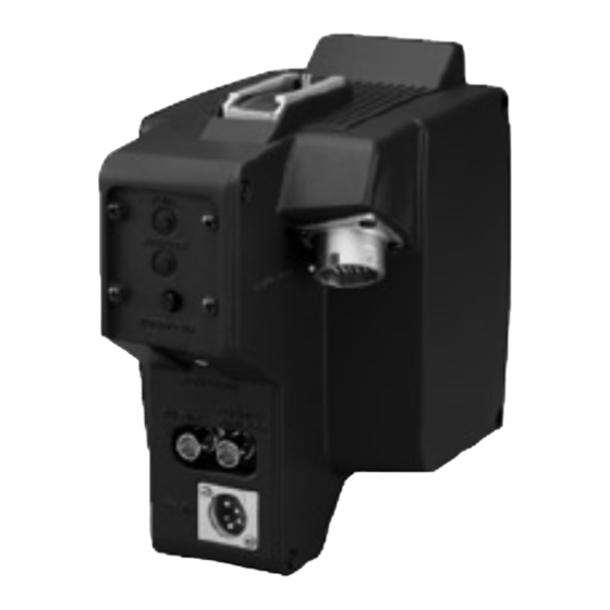
Page 7: Location And Functions Of Parts
4 CCU/VTR/CMA connector 5 INTERCOM knob 6 EARPHONE jack 7 INTERCOM connector 8 PROMPT/GENLOCK connector 9 DC IN connector 0 SDI OUT connector Note The CALL button does not function in a system which combines the CA-D50 with a CCU-M5A/M5AP. - Page 8 Location and Functions of Parts 3 RET/VTR button Use this button when a CCU-D50/ D50P/M5A/M5AP or VTR is connected to the CCU/VTR/CMA connector. When a CCU-D50/D50P/M5A/ M5AP is connected: Holding down this button displays return video in the viewfinder. When the button is released, the viewfinder returns to the video being shot by the camera.
-
Page 9: Mounting On Video Camera
Mounting on Video Camera This unit is dockable with a DXC-D35/D35WS series digital video camera. Before mounting on a DXC-D35/D35WS series camera, remove the camera’s shoulder pad. On how to remove the shoulder pad, refer to the procedure of mounting a VTR described in the operating instructions for the DXC-D35/D35WS series camera. - Page 10 Mounting on Video Camera Tighten the two screws in the figure. Tighten the two screws on the bottom side of the camera. Attach the shoulder pad. To remove this unit from the camera Carry out the mounting procedure in reverse. Attachment screws...
-
Page 11: Mounting The Bkp-L551 Battery Adapter
Mounting the BKP-L551 Battery Adapter Remove the 4 screws on the back side of this unit. Attach the battery adaptor mounting bracket (Part number 3- 690-850-01; not supplied) with the screws removed in step 1. Using the wrench and screws supplied with the BKP-L551, mount the BKP-L551 Battery Adapter (not supplied) on the... - Page 12 Mounting the BKP-L551 Battery Adapter Connect the 4-pin connector of the BKP-L551 to the DC IN connector of this unit. To remove the battery adapter Repeat the mounting procedure in reverse. DC IN connector 4-pin connector...
-
Page 13: Notes On Use
Notes on Use Use and storage locations Avoid using or storing the unit in the following places: • Where it is subject to extremes of temperature (operating temperature: –10ºC to +45ºC (14ºF to 113ºF)). Note that in summer the temperature in a car with the windows closed can reach 50ºC (122ºF). -
Page 14: Specifications
CCU/VTR/CMA Z type 26-pin (1) PROMPTER OUT/GENLOCK IN BNC type (1), 1 Vp-p, 75 Ω DC IN XLR 4-pin (1), 10.5 to 17 V DC Sony Corporation Camera connector SDI OUT INTERCOM EARPHONE Accessories supplied Operating Instructions (1) CD-ROM Manual (1)