Table of Contents
Advertisement
HCD-DX60AV/RG70AV
SERVICE MANUAL
Ver 1.2 2003.07
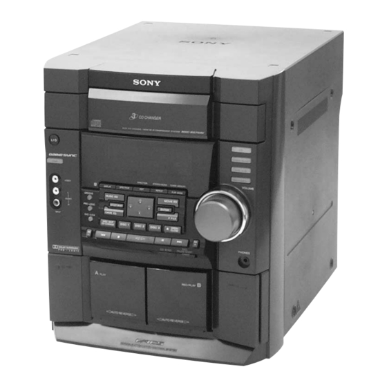
• HCD-DX60AV/RG70AV is the tuner,
deck, CD and amplifier section in MHC-
DX60AV/RG70AV.
Dolby noise reduction manufactured under license
from Dolby Laboratories Licensing Corporation.
"DOLBY" and the double-D symbol ; are trade-
marks of Dolby Laboratories Licensing Corporation.
AUDIO POWER SPECIFICATIONS:
(HCD-RG70AV US model only)
POWER OUTPUT AND TOTAL
HARMONIC DISTORTION:
with 6 ohm loads both channels driven, from
120 – 10,000 Hz; rates 60 watts per channel
minimum RMS power, with no more than 10%
total harmonic distortion from 250 milliwatts to
rated output.
Amplifier section
North American model:
HCD-RG70AV
Front speaker:
Continuous RMS power output (reference)
Total harmonic distortion less than 0.07%
Center speaker:
Continuous RMS power output (reference)
Rear speaker:
Continuous RMS power output (reference)
Sony Corporation
9-873-839-13
2003G05-1
Home Audio Company
C 2003.07
Published by Sony Engineering Corporation
Photo: HCD-RG70AV
CD
Section
Tape deck
Section
SPECIFICATIONS
European model:
HCD-RG70AV
Front speaker:
DIN power output (rated) 40 + 40 watts
Continuous RMS power output (reference)
Music power output (reference)
Center speaker:
DIN power output (rated) 25 watts
Continuous RMS power output (reference)
Music power output (reference)
60 + 60 watts
(6 ohms at 1 kHz,
Rear speaker:
10% THD)
DIN power output (rated) 25 + 25 watts
(6 ohms at 1 kHz,
Continuous RMS power output (reference)
30 watts)
Music power output (reference)
40 watts
(6 ohms at 1 kHz,
10% THD)
40 + 40 watts
MINI HI-FI COMPONENT SYSTEM
(6 ohms at 1 kHz,
10% THD)
Model Name Using Similar Mechanism
CD Mechanism Type
Base Unit Name
Optical Pick-up Block Name
Optical Pick-up Name
Model Name Using Similar Mechanism
Tape Transport Mechanism Type
(6 ohms at 1 kHz, DIN)
50 + 50 watts (6 ohms at
1 kHz, 10% THD)
95 + 95 watts (6 ohms at 1
kHz, 10% THD)
(6 ohms at 1 kHz, DIN)
35 watts (6 ohms at 1 kHz,
10% THD)
65 watts (6 ohms at 1 kHz,
10% THD)
(6 ohms at 1 kHz, DIN)
35 + 35 watts (6 ohms at
1 kHz, 10% THD)
65 + 65 watts (6 ohms at 1
kHz, 10% THD)
US Model
AEP Model
HCD-RG70AV
E Model
HCD-DX60AV
HCD-DX90
CDM58B-K6BD38
BU-K6BD38
KSM-213DCP
KSS-213D
NEW
CWL44RR-31
– Continued on next page –
Advertisement
Table of Contents

Related Manuals for Sony HCD-DX60AV


Summary of Contents for Sony HCD-DX60AV
- Page 1 SERVICE MANUAL US Model AEP Model Ver 1.2 2003.07 HCD-RG70AV E Model HCD-DX60AV • HCD-DX60AV/RG70AV is the tuner, deck, CD and amplifier section in MHC- DX60AV/RG70AV. Photo: HCD-RG70AV Dolby noise reduction manufactured under license Model Name Using Similar Mechanism HCD-DX90 from Dolby Laboratories Licensing Corporation.
- Page 2 4-track 2-channel stereo Front speaker: Frequency response 40 – 13,000 Hz (±3 dB), DIN power output (rated) 45 + 45 watts using Sony TYPE I (6 ohms at 1 kHz, DIN) cassettes Continuous RMS power output (reference) ±0.2% W.Peak (IEC)
-
Page 3: Leakage Test
LINE WITH MARK 0 ON THE SCHEMATIC DIAGRAMS AND IN THE PARTS LIST ARE CRITICAL TO SAFE OPERATION. REPLACE THESE COMPONENTS WITH SONY PARTS WHOSE PART NUMBERS APPEAR AS SHOWN IN THIS MANUAL OR IN SUPPLEMENTS PUB- LISHED BY SONY. -
Page 4: Table Of Contents
HCD-DX60AV/RG70AV TABLE OF CONTENTS GENERAL ..............5 DISASSEMBLY 2-1. Disassembly Flow ............8 2-2. Case (Top) ............... 9 2-3. CD Door ................9 2-4. CD Mechanism Deck (CDM58B-K6BD38) ....10 2-5. Front Panel Section ............10 2-6. Tape Mechanism Deck ............ 11 2-7. -
Page 5: General
HCD-DX60AV/RG70AV SECTION 1 This section is extracted from instruction manual. GENERAL Parts Identification The items are arranged in alphabetical order. Refer to the pages indicated in parentheses for details. Main unit 1 2 3 4 9 0 qa wl wk... -
Page 6: Setting The Time
HCD-DX60AV/RG70AV – Rear Panel – Setting the time Turn on the system. Press CLOCK/TIMER SET on the remote. Proceed to step 5 when “CLOCK” appears in the display. Press v or V repeatedly to select “SET CLOCK”. Press ENTER. Press v or V repeatedly to set the hour. -
Page 7: Remote Control
HCD-DX60AV/RG70AV Remote Control 1 2 3 4 CD w; (10 — 12, 17, 18) P FILE qh (21) BUTTON DESCRIPTIONS CLEAR 7 (12) PRESET EQ qk (19) CLOCK/TIMER SELECT 2 PRESET + wd (14) ?/1 (power) 4 (19, 23) PRESET — wd (14) -
Page 8: Disassembly
HCD-DX60AV/RG70AV SECTION 2 DISASSEMBLY • This set can be disassembled in the order shown below. 2-1. DISASSEMBLY FLOW 2-2. CASE (TOP) (Page 9) 2-3. CD DOOR (Page 9) 2-4. CD MECHANISM DECK (CDM58B-K6BD38) (Page 10) 2-5. FRONT PANEL SECTION 2-9. BASE UNIT (BU-K6BD38) -
Page 9: Case (Top)
HCD-DX60AV/RG70AV Note: Follow the disassembly procedure in the numerical order given. 2-2. CASE (TOP) case (top) 5 two screws (case 3 TP2) 9 four screws (+BVTP 3 × 10) 7 two screws 8 case ( side L) (+BVTP 3 × 10) -
Page 10: Cd Mechanism Deck (Cdm58B-K6Bd38)
HCD-DX60AV/RG70AV 2-4. CD MECHANISM DECK (CDM58B-K6BD38) CD mechanism deck (CDM58B-K6BD38) connector CN701) wire (flat type) (19 core) (CN407) 4 screw (+BVTP 3 × 10) screw (+BVTP 3 × 10 2-5. FRONT PANEL SECTION 4 two screws (+BVTP 3 × 10 ) -
Page 11: Tape Mechanism Deck
HCD-DX60AV/RG70AV 2-6. TAPE MECHANISM DECK 1 five screws 2 harness (+BVTP 2.6 × 8) 1 screw (+BVTP 2.6 × 8) 3 Tape mechanism deck 2-7. BACK PANEL SECTION back panel section 1 connector (CN506) 1 connector (CN901) 3 seven screws (+BVTP 3 ×... -
Page 12: Main Board
HCD-DX60AV/RG70AV 2-8. MAIN BOARD MAIN board 2 MAIN board 1 two screws (+BVTP 3 × 10) 2-9. BASE UNIT (BU-K6BD38) 2 screw (+PTPWH M2.6) 3 holder BU assy base unit qd two insulators (BU-K6BD38) qa screws (DIA. 12) qd two insulators 0 two screws (+PTPWH M2.6) -
Page 13: Driver Board, Motor Board, Address Sensor Board
HCD-DX60AV/RG70AV 2-10. DRIVER BOARD, MOTOR BOARD, ADDRESS SENSOR BOARD qs screw (+PTPWH 2.6 × 8) 6 two screws (BTTP M2.6) 0 MOTOR board wire (flat type) (8 core) (CN721) 5 Remove the two solderings of motor. qf screw (BTTP M2.6) -
Page 14: Test Mode
HCD-DX60AV/RG70AV SECTION 3 TEST MODE [MC Cold Reset] [Change-over of AM Tuner Step between 9 kHz and • The cold reset clears all data including preset data stored in the 10 kHz] RAM to initial conditions. Execute this mode when returning •... - Page 15 HCD-DX60AV/RG70AV [MC Test Mode] [Indicating Version of the Micro Processor] • This mode is used to check operations of the respective sections When power is off and the set is not in power save mode, (the status of Amplifier, Tuner, CD and Tape.
- Page 16 HCD-DX60AV/RG70AV [Aging Mode] This mode can be used for operation check of CD section and tape deck section. • If an error occurred: The aging operation stops and display status. • If no error occurs: The aging operation continues repeatedly.
- Page 17 HCD-DX60AV/RG70AV 2) Operation during aging mode In the aging mode, the program is executed in the following sequence. (1) The disc tray opens and closes. (2) The mechanism accesses DISC 2 and makes an attempt to read TOC. However, since there are no discs, a message “CD2 NO DISC”...
-
Page 18: Electrical Adjustments
HCD-DX60AV/RG70AV SECTION 4 ELECTRICAL ADJUSTMENTS 2. Turn the adjustment screw and check output peaks. If the peaks DECK SECTION 0 dB=0.775 V do not match for L-CH and R-CH, turn the adjustment screw so that outputs match within 1dB of peak. -
Page 19: Tuner Section
HCD-DX60AV/RG70AV DECK B Tape Speed Adjustment TUNER SECTION Note: Start the Tape Speed adjustment as below after setting to the test FM Tuned Level Adjustment mode. Procedure: FM RF SSG 1. Turn the power switch on. 2. Press the button,... -
Page 20: Cd Section
HCD-DX60AV/RG70AV Note: Clear RF signal waveform means that the shape “◊” can be CD SECTION clearly distinguished at the center of the waveform. Note : 1. CD Block is basically designed to operate without adjustment. RF signal waveform Therefore, check each item in order given. - Page 21 HCD-DX60AV/RG70AV Adjustment Location: [BD BOARD] (Conductor Side) (XPCK) (AGCCON) IC103 (TEO) IC101 (FEO) (FEI) (VC) (RF) (DGND)
- Page 22 HCD-DX60AV/RG70AV MEMO...
-
Page 23: Diagrams
HCD-DX60AV/RG70AV SECTION 5 DIAGRAMS 5-1. BLOCK DIAGRAM – TUNER/CD Section – (DX60AV/RG70AV: US) JK101 (DX60AV/RG70AV: US) AM/FM IF AMP, MPX ANTENNA IC101 FE101 Q101 • R-CH : R-ch is omitted due to same as L-ch. CF101 CF102 RF IF BUFFER L-CH FM 75Ω... -
Page 24: Block Diagram - Main Section (1/2)
HCD-DX60AV/RG70AV 5-2. BLOCK DIAGRAM – MAIN Section (1/2) – L-CH TU L (Page 23) FRONT L OUT OUTL 5 BAND (Page 25) CD L OUT CD L (Page 23) JK301 (1/4) MD/VD MODE MD (VIDEO) SELECTOR R-CH JK301 (2/4) GAME L... -
Page 25: Block Diagram - Main Section (2/2)
HCD-DX60AV/RG70AV 5-3. BLOCK DIAGRAM – MAIN Section (2/2) – JACK701 R-CH PHONES MUTING MUTING DRIVE Q423 Q413 HP SW POWER AMP (Page 26) IC501 JK401 FRONT L OUT POWER RL401 – –VE FRONT SPEAKER (Page 24) IMPEDANCE – RELAY USE 6 – 16Ω... -
Page 26: Block Diagram - Display/Power Section
HCD-DX60AV/RG70AV 5-4. BLOCK DIAGRAM – DISPLAY/POWER Section – DISPLAY CONTROL IC701 T911 POWER HP SW 17 HEADPHONE F515 TRANSFORMER S0 – S29 (Page 25) RECT D514 VR701 FLD1 FLUORESCENT VOLUME (+VCC) INDICATOR REAR/CENTER POWER TUBE G0 – G11 13 VOL A... -
Page 27: Note For Printed Wiring Boards And Schematic Diagrams
HCD-DX60AV/RG70AV 5-5. NOTE FOR PRINTED WIRING BOARDS AND SCHEMATIC DIAGRAMS (In addition to this, the necessary note is printed in each block) Note on Printed Wiring Boards: Note on Schematic Diagram: • Circuit Boards Location • All capacitors are in µF unless otherwise noted. pF: µµF •... -
Page 28: Printed Wiring Board - Bd Board
HCD-DX60AV/RG70AV 5-6. PRINTED WIRING BOARD – BD Board – • See page 27 for Circuit Boards Location. • Semiconductor Location Ref. No. Location IC101 IC102 IC103 Q101 TP (TEO) (VC) TP (FEO) (KSM-213DCP) TP (RF) TP (FEI) TP (AGCCON) IC101... -
Page 29: Schematic Diagram - Bd Board
HCD-DX60AV/RG70AV 5-7. SCHEMATIC DIAGRAM – BD Board – • See page 44 for Wavefoms. • See page 44 for IC Block Diagrams. (TEO) (FEO) (VC) (RFO) OPTICAL PICK-UP BLOCK (KSM-213DCP) (AGCCON) 2SB710A-RTX (FE1) (XPCK) MAIN BOARD (4/4) CN407 (Page 33) •... -
Page 30: Schematic Diagram – Main Board (1/4)
HCD-DX60AV/RG70AV 5-8. SCHEMATIC DIAGRAM – MAIN Board (1/4) – • See page 44 for Wavefoms. • See page 44 for IC Block Diagrams. MAIN BOARD (1/4) (DX60AV/RG70AV : US) (RG70AV : AEP) FE102 (DX60AV/RG70AV : US) 75Ω (DX60AV/RG70AV : US) 10.0... -
Page 31: Schematic Diagram - Main Board (2/4)
HCD-DX60AV/RG70AV 5-9. SCHEMATIC DIAGRAM – MAIN Board (2/4) – • See page 44 for Wavefoms. • See page 44 for IC Block Diagrams. MAIN BOARD (2/4) Q424, 425 FAN MOTOR DRIVE IC201 0.1U 10.0 REC/PB EQ AMP 11.0 IC B/D 0.018U... -
Page 32: Schematic Diagram - Main Board (1/4)
HCD-DX60AV/RG70AV 5-10. SCHEMATIC DIAGRAM – MAIN Board (3/4) – • See page 44 for IC Block Diagrams. MAIN BOARD (Page 30) (1/4) MAIN BOARD (3/4) I 80 i I 79 i I 78 i 0.001U I 77 i JK301 (1/4) 0.1U... -
Page 33: Schematic Diagram - Main (4/4)/Digital Out Boards
HCD-DX60AV/RG70AV 5-11. SCHEMATIC DIAGRAM – MAIN (4/4)/DIGITAL OUT Boards – • See page 44 for Wavefoms. MAIN BOARD (Page 31) (2/4) MAIN BOARD (4/4) Q411, 412 RELAY DRIVE 0.001U I 80 i – REAR SPEAKER 19.0 I 79 i IMPEDANCE USE 6-16Ω... -
Page 34: Printed Wiring Boards - Main/Digital Out Boards
HCD-DX60AV/RG70AV 5-12. PRINTED WIRING BOARDS – MAIN/DIGITAL OUT Boards – • See page 27 for Circuit Boards Location. • Semiconductor Location Ref. No. Location Ref. No. Location DIGITAL OUT BOARD D101 D-15 Q202 D104 E-11 Q203 D107 Q204 CD DIGITAL... -
Page 35: Printed Wiring Boards - Address Sensor/Driver/Motor Boards
HCD-DX60AV/RG70AV 5-13. PRINTED WIRING BOARDS – ADDRESS SENSOR/DRIVER/MOTOR Boards – • See page 27 for Circuit Boards Location. • Semiconductor Location Ref. No. Location D701 IC701 B-10 IC711 C712 IC711 (14) (14) (14) There are a few cases that the part printed on this diagram isn’t mounted in this model. -
Page 36: Rear/Center Amp Board
HCD-DX60AV/RG70AV 5-15. PRINTED WIRING BOARD – REAR/CENTER AMP Board – • See page 27 for Circuit Boards Location. • Semiconductor Location Ref. No. Location D514 D515 POWER AMP BOARD (Page 38) CN505 D516 D517 REAR/CENTER AMP BOARD D518 IC503 Q505... -
Page 37: Schematic Diagram - Rear/Center Amp Board
HCD-DX60AV/RG70AV 5-16. SCHEMATIC DIAGRAM – REAR/CENTER AMP Board – REAR/CENTER AMP BOARD CN917 (Page 43) 6.3A/125V (RG70AV : US) T6.3A/250V (DX60AV/RG70AV : AEP) TRANSFORMER BOARD CN916 6.3A/125V (RG70AV : US) T6.3A/250V (DX60AV/RG70AV : AEP) IC503 POWER AMP IC503 (1/3) STK402-240 (REAR AMP L-CH) 32.0... -
Page 38: Printed Wiring Boards - Power Amp/Sensor Boards
HCD-DX60AV/RG70AV 5-17. PRINTED WIRING BOARDS – POWER AMP/SENSOR Boards – • See page 27 for Circuit Boards Location. POWER AMP BOARD SENSOR BOARD IC501 (CHASSIS) (11) 1-682-255- (RG70AV: AEP) MAIN BOARD CN402 (Page 34) (RG70AV: AEP) • Semiconductor Location MAIN BOARD Ref. -
Page 39: Schematic Diagram - Power Amp/Sensor Boards
HCD-DX60AV/RG70AV 5-18. SCHEMATIC DIAGRAM – POWER AMP/SENSOR Boards – POWER AMP BOARD 37.0 –0.1 37.7 IC501 (1/2) STK402 –0.1 –36.0 37.7 1.2k (Page 43) 1500P 37.0 Q503, 504 POWER CONTROL TRANSFORMER OVER –36.0 BOARD 37.7 11.7 LOAD CN915 DETECT –35.0... -
Page 40: Printed Wiring Boards - Panel/Key Boards
HCD-DX60AV/RG70AV 5-19. PRINTED WIRING BOARDS – PANEL/KEY Board – • See page 27 for Circuit Boards Location. • Semiconductor Location PANEL BOARD Ref. No. Location D701 A-13 FLD1 D702 (FLUORESCENT INDICATOR TUBE) D703 D704 D705 D706 C-13 D707 D708 TUNER/BAND... -
Page 41: Schematic Diagram - Panel/Key Boards
HCD-DX60AV/RG70AV 5-20. SCHEMATIC DIAGRAM – PANEL/KEY Boards – PANEL BOARD (FLOURESCENT INDICATOR TUBE) (Page 32) MAIN BOARD (3/4) –25.3 CN302 –2.8 JW714 –9 ~ –17 –9 ~ –17 D702 – 706, –16 ~ –20 D716 – 720 VIDEO LTL77HKYTNN –18 ~ –21... -
Page 42: Sub Transformer Boards
HCD-DX60AV/RG70AV Ver 1.1 5-21. PRINTED WIRING BOARDS – TRANSFORMER/SUB TRANSFORMER Boards – • See page 27 for Circuit Boards Location. • Semiconductor Location Ref. No. Location TRANSFORMER BOARD D901 (CHASSIS) D902 D903 D904 (RG70AV) POWER TRANSFORMER D905 D911 D912 D913... -
Page 43: Schematic Diagram - Transformer/Sub Transformer Boards
HCD-DX60AV/RG70AV 5-22. SCHEMATIC DIAGRAM – TRANSFORMER/SUB TRANSFORMER Boards – TRANSFORMER BOARD F914 (Page 37) POWER TRANSFORMER 6.3A/125V (RG70AV : US) T6.3A/250V (DX60AV/RG70AV : AEP) (DX60AV/RG70AV : AEP) REAR/CENTER JW912 BOARD F919 6.3A/125V SUB TRANSFORMER BOARD CN917 F920 (RG70AV : US) 6.3A/125V... - Page 44 HCD-DX60AV/RG70AV • Waveforms • IC Block Diagrams – BD Board – – MAIN Board – – BD Board – 1 IC101 yj (XTAO) (CD Play mode) 1 IC102 wf (XOUT) 6 Q209 (Collector) IC101 CXD2587Q 13.6 Vp-p 6.4 Vp-p 4.7 Vp-p...
- Page 45 HCD-DX60AV/RG70AV IC103 CXA2568M-T6 HOLD APC PD AMP LC/PD APC LD AMP – LD ON – – – HOLD SW AGC CONT AGC VTH 50µA RF BOT – – – – RFTC RF SUMMING AMP RF EQ AMP RF I RF O –...
- Page 46 HCD-DX60AV/RG70AV – DRIVER Board – IC701 BA6956AN CONTROL LOGIC – MAIN Board – IC103 BU1924 12 11 10 CLOCK TEST PLL 57kHz RDS/ARI 1187.5Hz COMPARATOR 8th SWITCHED BIPHASE CAPACITOR DECODER FILTER DEFFERENTIAL ANTI-ALIASING DECODER FILTER IC201 TA8189N METAL TAPE A...
- Page 47 HCD-DX60AV/RG70AV IC101 BA1450 AM IF VREG DECODER DRIVER COMP IC102 LC72130 PHASE DETECTOR CHARGE PUMP UNLOCK POWER DETECTOR RESET REFERENCE SWALLOW COUNTER DIVIDER 1/16, 1/17 4BITS 12BITS PROGRAMMABLE DRIVER UNIVERSAL DATA SHIFT REGISTER LATCH COUNTER 3 4 5 6...
- Page 48 HCD-DX60AV/RG70AV IC301 BH3878KS2 47 46 45 44 43 42 41 39 38 37 36 INLE OUTL DIGITAL INRE CONTROL OUTR + – 105Hz 340Hz –5dB –6dB –5dB –6dB 1KHz 3.4KHz 10.5KHz RECL RECR MODE SELECTOR VFC1 VFC2 DPLL1 DPLL2 0to30dB –30dBto–∞...
- Page 49 HCD-DX60AV/RG70AV IC302 M62464FP 61 60 59 58 57 56 55 54 53 52 51 50 49 48 47 46 45 44 43 DUAL-TIME CONSTANT MODIFIED DO-SW FULL WAVE DIFFERENCE B-TYPE RECTIFER AMPLIFIERS THRESHOLD SWITCHES NR DECODER L+R L-R NGC3 SEQUENCER...
-
Page 50: Ic Pin Function Description
HCD-DX60AV/RG70AV 5-23. IC PIN FUNCTION DESCRIPTION • MAIN BOARD IC401 M30622MCA-B43FP (SYSTEM CONTROLLER) Pin No. Pin Name Description S-OUT Serial data output to the display control (IC701) S-CLK Serial data transfer clock signal output to the display control (IC701) S-BSY Busy signal input from the display control (IC701) “L”: busy... - Page 51 HCD-DX60AV/RG70AV Pin No. Pin Name Description LOAD-IN Turn motor control signal output to the BA6956AN (IC701) LOAD-OUT Turn motor control signal output to the BA6956AN (IC701) OPEN Tray open detect signal input terminal “L”: open CLOSE Tray close detect signal input terminal “L”: close...
- Page 52 HCD-DX60AV/RG70AV Pin No. Pin Name Description B-SHUT Shut off detection signal input from the deck-B side reel pulse detector SP/VACS Spectrum analyzer signal input from the BH3878KS2 (IC301) MODEL-IN Model select signal input terminal SPEC-IN Version select signal input terminal —...
- Page 53 HCD-DX60AV/RG70AV • PANEL BOARD IC701 µPD780232GC-031-8BT (DISPLAY CONTROL) Pin No. Pin Name Description — Power supply terminal (+5V) — Ground terminal System clock input terminal (5MHz) System clock output terminal (5MHz) — Not used (fixed at “L”) RESET Reset signal input from the system controller (IC401)
-
Page 54: Exploded Views
HCD-DX60AV/RG70AV SECTION 6 EXPLODED VIEWS NOTE: • -XX and -X mean standardized parts, so they • Items marked “*” are not stocked since they The components identified by mark 0 or dotted line with mark may have some difference from the original are seldom required for routine service. -
Page 55: Front Panel Section
HCD-DX60AV/RG70AV 6-2. FRONT PANEL SECTION not supplied not supplied Ref. No. Part No. Description Remark Ref. No. Part No. Description Remark 4-234-015-01 VOL KNOB RING A-4726-316-A KEY BOARD, COMPLETE 4-234-019-01 VOLUME KNOB 4-224-562-21 BRACKET (HEART CAM L) A-4735-179-A PANEL ASSY, FRONT... -
Page 56: Main Board Section
HCD-DX60AV/RG70AV Ver 1.1 6-3. MAIN BOARD SECTION not supplied not supplied T911 not supplied not supplied The components identified by mark 0 or dotted line with mark 0 are critical for safety. Replace only with part number specified. Ref. No. -
Page 57: Cd Mechanism Deck Section (Cdm58B-K6Bd38)
HCD-DX60AV/RG70AV 6-4. CD MECHANISM DECK SECTION (CDM58B-K6BD38) M721 not supplied BU-K6BD38 Ref. No. Part No. Description Remark Ref. No. Part No. Description Remark 4-218-254-21 SCREW (M2.6), +PTPWH 1-471-035-11 MAGNET ASSY 4-231-187-01 CAM (RELAY) X-4953-282-1 PULLEY (A) ASSY, CHUCKING 4-231-177-01 TABLE (NEW) -
Page 58: Base Unit Section (Bu-K6Bd38)
HCD-DX60AV/RG70AV Ver 1.2 6-5. BASE UNIT SECTION (BU-K6BD38) The components identified by mark 0 or dotted line with mark 0 are critical for safety. Replace only with part number specified. Ref. No. Part No. Description Remark Ref. No. Part No. -
Page 59: Electrical Parts List
HCD-DX60AV/RG70AV SECTION 7 ELECTRICAL PARTS LIST ADDRESS SENSOR NOTE: • Due to standardization, replacements in the • Items marked “*” are not stocked since they The components identified by mark 0 or dotted line with mark parts list may be different from the parts speci- are seldom required for routine service. - Page 60 HCD-DX60AV/RG70AV DIGITAL OUT DRIVER Ref. No. Part No. Description Remark Ref. No. Part No. Description Remark < CONNECTOR > R106 1-216-049-11 RES-CHIP 1/10W R107 1-216-073-00 RES-CHIP 1/10W CN701 1-785-336-11 PIN, CONNECTOR (LIGHT ANGLE) 10P R108 1-216-061-00 RES-CHIP 3.3K 1/10W CN702...
- Page 61 HCD-DX60AV/RG70AV MAIN Ref. No. Part No. Description Remark Ref. No. Part No. Description Remark C103 1-162-970-11 CERAMIC CHIP 0.01uF R733 1-249-420-11 CARBON 1.8K 1/4W (DX60AV/RG70AV: US) R734 1-249-422-11 CARBON 2.7K 1/4W C104 1-104-660-11 ELECT 47uF R735 1-247-843-11 CARBON 3.3K 1/4W...
- Page 62 HCD-DX60AV/RG70AV MAIN Ref. No. Part No. Description Remark Ref. No. Part No. Description Remark C171 1-104-660-11 ELECT 47uF (RG70AV: AEP) C231 1-104-660-11 ELECT 47uF C232 1-104-660-11 ELECT 47uF C172 1-162-964-11 CERAMIC CHIP 0.001uF C233 1-164-361-11 CERAMIC CHIP 0.047uF C173 1-164-156-11 CERAMIC CHIP 0.1uF...
- Page 63 HCD-DX60AV/RG70AV MAIN Ref. No. Part No. Description Remark Ref. No. Part No. Description Remark C335 1-136-169-00 FILM 0.22uF C336 1-136-169-00 FILM 0.22uF C393 1-136-169-00 FILM 0.22uF C337 1-136-169-00 FILM 0.22uF C394 1-136-165-00 FILM 0.1uF C395 1-130-491-00 MYLAR 0.047uF C338 1-136-169-00 FILM 0.22uF...
- Page 64 HCD-DX60AV/RG70AV MAIN Ref. No. Part No. Description Remark Ref. No. Part No. Description Remark C477 1-162-960-11 CERAMIC CHIP 220PF < DIODE > C482 1-109-953-11 ELECT 2.2uF D101 8-719-914-42 DIODE DA204K-T-146 C483 1-109-953-11 ELECT 2.2uF D104 8-719-978-33 DIODE UDZSTE-176.8B C484 1-109-953-11 ELECT 2.2uF...
- Page 65 HCD-DX60AV/RG70AV MAIN Ref. No. Part No. Description Remark Ref. No. Part No. Description Remark < FRONT END > JR203 1-216-864-11 METAL CHIP 1/16W JR204 1-216-864-11 METAL CHIP 1/16W FE101 1-693-478-11 FRONT END (FM3 GANGS) (DX60AV/RG70AV: US) JR205 1-216-864-11 METAL CHIP...
- Page 66 HCD-DX60AV/RG70AV MAIN Ref. No. Part No. Description Remark Ref. No. Part No. Description Remark Q217 8-729-119-78 TRANSISTOR 2SC2785TP-HFE R103 1-216-819-11 METAL CHIP 1/16W Q218 8-729-119-78 TRANSISTOR 2SC2785TP-HFE R104 1-216-811-11 METAL CHIP 1/16W Q301 8-729-141-30 TRANSISTOR 2SC3623ATP-LK R105 1-216-823-11 METAL CHIP 1.5K...
- Page 67 HCD-DX60AV/RG70AV MAIN Ref. No. Part No. Description Remark Ref. No. Part No. Description Remark R211 1-216-833-11 METAL CHIP 1/16W R302 1-216-829-11 METAL CHIP 4.7K 1/16W R303 1-216-831-11 METAL CHIP 6.8K 1/16W R212 1-216-841-11 METAL CHIP 1/16W R304 1-216-831-11 METAL CHIP 6.8K...
- Page 68 HCD-DX60AV/RG70AV MAIN Ref. No. Part No. Description Remark Ref. No. Part No. Description Remark R359 1-216-825-11 METAL CHIP 2.2K 1/16W R414 1-216-819-11 METAL CHIP 1/16W R415 1-216-819-11 METAL CHIP 1/16W R360 1-216-825-11 METAL CHIP 2.2K 1/16W R361 1-216-845-11 METAL CHIP...
- Page 69 HCD-DX60AV/RG70AV MAIN MOTOR Ref. No. Part No. Description Remark Ref. No. Part No. Description Remark R470 1-216-829-11 METAL CHIP 4.7K 1/16W R4102 1-216-864-11 METAL CHIP 1/16W (DX60AV/RG70AV: US) R471 1-216-829-11 METAL CHIP 4.7K 1/16W R4103 1-216-864-11 METAL CHIP 1/16W R472...
- Page 70 HCD-DX60AV/RG70AV PANEL Ref. No. Part No. Description Remark Ref. No. Part No. Description Remark D717 8-719-084-19 LED LTL77HKYTNN (TAPE A/B) A-4726-315-A PANEL BOARD, COMPLETE D718 8-719-084-19 LED LTL77HKYTNN (CD) ********************** D719 8-719-084-19 LED LTL77HKYTNN (TUNER/BAND) < CAPACITOR > D720 8-719-084-19 LED LTL77HKYTNN (GAME)
- Page 71 HCD-DX60AV/RG70AV PANEL POWER AMP Ref. No. Part No. Description Remark Ref. No. Part No. Description Remark R765 1-247-903-00 CARBON 1/4W C558 1-130-493-00 MYLAR 0.068uF R768 1-247-807-31 CARBON 1/4W C559 1-126-965-11 ELECT 22uF C591 1-130-777-00 MYLAR 0.1uF 100V R769 1-249-401-11 CARBON...
- Page 72 HCD-DX60AV/RG70AV POWER AMP REAR/CENTER AMP Ref. No. Part No. Description Remark Ref. No. Part No. Description Remark R522 1-249-441-11 CARBON 100K 1/4W R523 1-249-409-11 CARBON 1/4W < CONNECTOR > R524 1-247-897-11 CARBON 560K 1/4W R525 1-249-437-11 CARBON 1/4W * CN507...
- Page 73 HCD-DX60AV/RG70AV Ver 1.1 REAR/CENTER AMP SENSOR SUB TRANSFORMER TRANSFORMER Ref. No. Part No. Description Remark Ref. No. Part No. Description Remark R539 1-260-120-11 CARBON 1/2W D902 8-719-200-82 DIODE 11ES2-NTA1B R540 1-260-328-11 CARBON 1/2W D903 8-719-200-82 DIODE 11ES2-NTA1B R542 1-249-429-11 CARBON...
- Page 74 HCD-DX60AV/RG70AV Ver 1.2 TRANSFORMER Ref. No. Part No. Description Remark Ref. No. Part No. Description Remark < RESISTOR > R905 1-249-429-11 CARBON 1/4W 0 R911 1-217-637-00 FUSIBLE 1/4W F R912 1-249-417-11 CARBON 1/4W R913 1-249-429-11 CARBON 1/4W R915 1-247-807-31 CARBON...
- Page 75 HCD-DX60AV/RG70AV MEMO...
-
Page 76: Revision History
HCD-DX60AV/RG70AV REVISION HISTORY Clicking the version allows you to jump to the revised page. Also, clicking the version at the upper right on the revised page allows you to jump to the next revised page. Ver. Date Description of Revision 2001.05...