Advertisement
www.freeservicemanuals.info
SERVICE MANUAL
ST-SP55 is the tuner section
in CMT-SP55MD or CMT-SP55TC.
FM stereo, FM/AM superheterodyne tuner
Input
AUX IN (phono jacks):
Output
AUX OUT (phono jacks): voltage 250 mV, impedance
FM tuner section
Tuning range
Aerial
Aerial terminals
Intermediate frequency
AM tuner section
Tuning range
European model:
Other models:
Aerial
Intermediate frequency
05/28/2012
SPECIFICATIONS
voltage 250 mV, impedance
47 kilohms
1 kilohm
87.5 – 108.0 MHz
(50 kHz step)
FM lead aerial
300 ohms unbalanced
10.7 MHz
531 – 1,602 kHz
(with the interval set at 9 kHz)
531 – 1,602 kHz
(with the interval set at 9 kHz)
530 – 1,710 kHz
(with the interval set at 10 kHz)
AM loop aerial
External aerial terminals
450 kHz
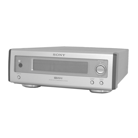
MICRO Hi-Fi COMPONENT SYSTEM
ST-SP55
General
Dimensions (w/h/d) incl. projecting parts and controls
Approx. 202 × 75 × 291 mm
Mass
Approx. 1.3 kg
Design and specifications are subject to change
without notice.
World of Free Manuals
AEP Model
UK Model
E Model
1
Advertisement
Table of Contents

Related Manuals for Sony ST-SP55


Summary of Contents for Sony ST-SP55
-
Page 1: Service Note
05/28/2012 World of Free Manuals ST-SP55 SERVICE MANUAL AEP Model UK Model E Model ST-SP55 is the tuner section in CMT-SP55MD or CMT-SP55TC. SPECIFICATIONS General FM stereo, FM/AM superheterodyne tuner Input Dimensions (w/h/d) incl. projecting parts and controls AUX IN (phono jacks): voltage 250 mV, impedance Approx. -
Page 2: Circuit Boards Location
www.freeservicemanuals.info 05/28/2012 World of Free Manuals SECTION 3 DIAGRAMS • WAVEFORMS THIS NOTE IS COMMON FOR PRINTED WIRING BOARDS AND SCHEMATIC DIAGRAMS. – MAIN BOARD – (In addition to this, the necessary note is printed in each block.) IC701 qa XCOUT For schematic diagrams. -
Page 3: Block Diagram
05/28/2012 World of Free Manuals ST-SP55 3-2. BLOCK DIAGRAM J210(2/2) AUX OUT IC401 INPUT SELECT/EVR Q221 R-CH IC231 MUTE LSELO BUFFER CN201 LOUT ST-L MD-L ST MUTE R-CH CD-L FM 75Ω RDS INT SEL-L TUNER RDS DATA UNIT STEREO... -
Page 4: Schematic Diagram - Main Section
05/28/2012 World of Free Manuals ST-SP55 3-3. SCHEMATIC DIAGRAM – MAIN SECTION – (Page 8) PIN FUNCTION (Page 8) (Page 8) -
Page 5: Printed Wiring Board - Main Section
05/28/2012 World of Free Manuals ST-SP55 3-4. PRINTED WIRING BOARD – MAIN SECTION – (Page 9) • Semiconductor Location Ref. No. Location D201 D282 D283 D291 D301 D701 D702 D731 D733 IC202 IC231 IC281 IC282 IC283 IC401 IC701 IC702... -
Page 6: Schematic Diagram - Panel Section
05/28/2012 World of Free Manuals ST-SP55 3-5. SCHEMATIC DIAGRAM – PANEL SECTION – LCD BACK LIGHT (Page 6) (Page 6) (Page 6) -
Page 7: Printed Wiring Board - Panel Section
05/28/2012 World of Free Manuals ST-SP55 3-6. PRINTED WIRING BOARD – PANEL SECTION – (Page 7) (Page 7) (Page 7) There are a few cases that the part isn't mounted in model is printed on diagram. -
Page 8: Ic Pin Functions
05/28/2012 World of Free Manuals ST-SP55 3-7. IC PIN FUNCTIONS • IC701 M30620MCA-A67FP MASTER CONTROL (MAIN BOARD) Pin No. Pin Name Function Pin No. Pin Name Function DP_DATA LCD data output. — Ground. DP_CLK LCD clock output. — Not used. -
Page 9: Ic Block Diagram
www.freeservicemanuals.info 05/28/2012 World of Free Manuals 3-8. IC BLOCK DIAGRAM IC401 LC75342 LOUT RROUT LBASS2 RBASS2 LBASS1 RBASS1 LTRE RTRE LSELO RSELO... -
Page 10: Table Of Contents
COMPONENTS IDENTIFIED BY MARK 0 OR DOTTED LINE WITH MARK 0 ON THE SCHEMATIC DIAGRAMS AND IN THE PARTS LIST ARE CRITICAL TO SAFE OPERATION. REPLACE THESE COMPONENTS WITH SONY PARTS WHOSE PART NUMBERS APPEAR AS SHOWN IN THIS MANUAL OR IN SUPPLEMENTS PUBLISHED BY SONY. - Page 11 www.freeservicemanuals.info 05/28/2012 World of Free Manuals SECTION 1 SERVICE NOTE This unit cannot be repaired by itself. When repairing, connect the whole system except for the speaker. CD Text Display • This unit displays CD text. Text is displayed for the first 50 track only and will not be displayed from the 51st track onwards. Do not suspect a fault in this case. In some cases, some special characters will not be displayed and may be replaced by other characters.
-
Page 12: Exploded View
www.freeservicemanuals.info 05/28/2012 World of Free Manuals SECTION 4 EXPLODED VIEW NOTE: • Abbreviation • Items marked “*” are not stocked since they are The components identified by AED : North European model seldom required for routine service. Some delay mark 0 or dotted line with mark should be anticipated when ordering these items. -
Page 13: Electrical Parts List
www.freeservicemanuals.info 05/28/2012 World of Free Manuals SECTION 5 MAIN ELECTRICAL PARTS LIST Ref. No. Part No. Description Remarks Ref. No. Part No. Description Remarks Note: • SEMICONDUCTORS • Due to standardization, replacements in the parts The components identified by In each case, u: µ , for example: list may be different from the parts specified in the mark 0 or dotted line with mark uA...: µ... - Page 14 www.freeservicemanuals.info 05/28/2012 World of Free Manuals MAIN Ref. No. Part No. Description Remarks Ref. No. Part No. Description Remarks C732 1-126-925-11 ELECT 470uF R213 1-249-418-11 CARBON 1.2K 1/4W F C733 1-104-664-11 ELECT 47uF R214 1-249-429-11 CARBON 1/4W C734 1-104-664-11 ELECT 47uF C735 1-164-159-11 CERAMIC...
- Page 15 www.freeservicemanuals.info 05/28/2012 World of Free Manuals PIN JACK MAIN PANEL Ref. No. Part No. Description Remarks Ref. No. Part No. Description Remarks R717 1-249-429-11 CARBON 1/4W < CONNECTOR > R718 1-249-429-11 CARBON 1/4W R719 1-247-807-31 CARBON 1/4W CN901 1-784-731-11 CONNECTOR, FFC 9P R720 1-249-429-11 CARBON 1/4W...
- Page 16 05/28/2012 World of Free Manuals ST-SP55 Ref. No. Part No. Description Remarks Ref. No. Part No. Description Remarks Sony Corporation 9-929-536-11 2000I097551-1 Audio Entertainment Group Printed in Hungary ©2000.9 Published by General Engineering Dept.