Table of Contents
Advertisement
Quick Links
SERVICE MANUAL
Ver. 1.0 2011.11
• The Tuner and CD sections have no adjustments.
FOR UNITED STATES CUSTOMERS. NOT
APPLICABLE IN CANADA, INCLUDING
IN THE PROVINCE OF QUEBEC.
POUR LES CONSOMMATEURS AUX
ÉTATS-UNIS. NON APPLICABLE AU
CANADA, Y COMPRIS LA PROVINCE DE
QUÉBEC.
AUDIO POWER SPECIFICATIONS
(BT4000P)
CEA2006 Standard
Power Output: 17 Watts RMS 4 at
4 Ohms < 1% THD+N
SN Ratio: 80 dBA
(reference: 1 Watt into 4 Ohms)
Tuner section (
BT4000P
)
FM
Tuning range: 87.5 – 107.9 MHz
Antenna (aerial) terminal:
External antenna (aerial) connector
Intermediate frequency: 25 kHz
Usable sensitivity: 8 dBf
Selectivity: 75 dB at 400 kHz
Signal-to-noise ratio: 80 dB (stereo)
Separation: 50 dB at 1 kHz
Frequency response: 20 – 15,000 Hz
AM
Tuning range: 530 – 1,710 kHz
Antenna (aerial) terminal:
External antenna (aerial) connector
Intermediate frequency:
9,115 kHz or 9,125 kHz/5 kHz
Sensitivity: 26 μV
Tuner section
(
BT4000U
)
FM
Tuning range: 87.5 – 108.0 MHz
Antenna (aerial) terminal:
External antenna (aerial) connector
Intermediate frequency: 25 kHz
Usable sensitivity: 8 dBf
Selectivity: 75 dB at 400 kHz
Signal-to-noise ratio: 80 dB (stereo)
Separation: 50 dB at 1 kHz
Frequency response: 20 – 15,000 Hz
MW/LW
Tuning range:
MW: 531 – 1,602 kHz
LW: 153 – 279 kHz
Antenna (aerial) terminal:
External antenna (aerial) connector
Intermediate frequency:
9,124.5 kHz or 9,115.5 kHz/4.5 kHz
Sensitivity: MW: 26 μV, LW: 45 μV
9-893-368-01
Sony Corporation
2011K33-1
©
2011.11
Published by Sony Techno Create Corporation
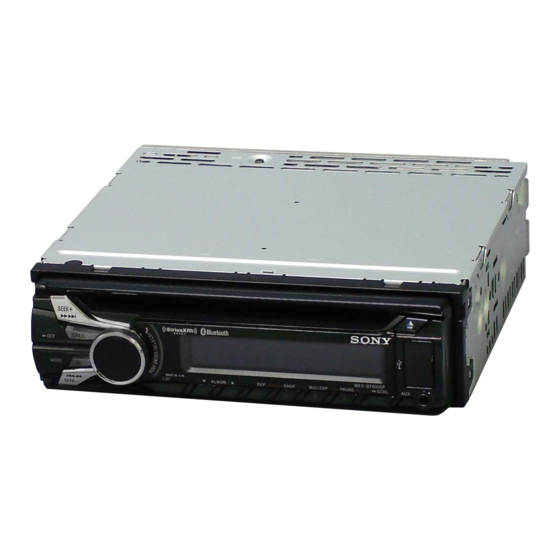
MEX-BT4000E/BT4000P/BT4000U/
Photo: MEX-BT4000P
Model Name Using Similar Mechanism
Mechanism Type
Optical Pick-up Name
SPECIFICATIONS
Tuner section
Tuner section
(
BT4000E
)
(
FM
FM
Tuning range: 87.5 – 108.0 MHz
Tuning range:
Antenna (aerial) terminal:
FM1/FM2: 87.5 – 108.0 MHz
(at 50 kHz step)
Intermediate frequency: 25 kHz
FM3:
65 – 74 MHz
Usable sensitivity: 8 dBf
(at 30 kHz step)
Selectivity: 75 dB at 400 kHz
Antenna (aerial) terminal:
Signal-to-noise ratio: 80 dB (stereo)
External antenna (aerial) connector
Separation: 50 dB at 1 kHz
Intermediate frequency: 25 kHz
Frequency response: 20 – 15,000 Hz
Usable sensitivity: 8 dBf
Selectivity: 75 dB at 400 kHz
MW
Signal-to-noise ratio: 80 dB (stereo)
Tuning range: 531 – 1,602 kHz
Separation: 50 dB at 1 kHz
Antenna (aerial) terminal:
Frequency response: 20 – 15,000 Hz
Intermediate frequency:
MW/LW
Tuning range:
Sensitivity: 26 μV
MW: 531 – 1,602 kHz
LW: 153 – 279 kHz
SW
Antenna (aerial) terminal:
Tuning range:
External antenna (aerial) connector
Intermediate frequency:
9,124.5 kHz or 9,115.5 kHz/4.5 kHz
Sensitivity: MW: 26 μV, LW: 45 μV
Antenna (aerial) terminal:
Intermediate frequency:
Tuner section
(
BT4050U
: E, Mexican models/
Sensitivity: 26 μV
BT4054U
)
CD Player section
FM
Signal-to-noise ratio: 120 dB
Tuning range:
Frequency response: 10 – 20,000 Hz
87.5 – 108.0 MHz (at 50 kHz step)
Wow and flutter: Below measurable limit
87.5 – 108.0 MHz (at 100 kHz step)
87.5 – 107.9 MHz (at 200 kHz step)
USB Player section
FM tuning step: 50 kHz/100 kHz/200 kHz
switchable
Interface: USB (Full-speed)
Antenna (aerial) terminal:
Maximum current: 1 A
External antenna (aerial) connector
Intermediate frequency: 25 kHz
Wireless Communication
Usable sensitivity: 8 dBf
Communication System:
Selectivity: 75 dB at 400 kHz
Signal-to-noise ratio: 80 dB (stereo)
Output:
Separation: 50 dB at 1 kHz
Frequency response: 20 – 15,000 Hz
Maximum communication range:
AM
Tuning range:
Frequency band:
531 – 1,602 kHz (at 9 kHz step)
530 – 1,710 kHz (at 10 kHz step)
Modulation method: FHSS
AM tuning step: 9 kHz/10 kHz switchable
Antenna (aerial) terminal:
External antenna (aerial) connector
Intermediate frequency:
9,124.5 kHz or 9,115.5 kHz/4.5 kHz
(at 9 kHz step)
9,115 kHz or 9,125 kHz/5 kHz
(at 10 kHz step)
Sensitivity: 26 μV
BT4050U/BT4054U
Canadian Model
Compatible Bluetooth Profiles*
BT4050U
: Saudi Arabia model)
External antenna (aerial) connector
*1 The actual range will vary depending on
*2 Bluetooth standard profiles indicate the
External antenna (aerial) connector
9,124.5 kHz or 9,115.5 kHz/4.5 kHz
Power amplifier section
Output: Speaker outputs
Speaker impedance: 4 – 8 ohms
SW1: 2,940 – 7,735 kHz
Maximum power output: 52 W 4 (at 4 ohms)
SW2: 9,500 – 18,135 kHz
(except for 10,140 – 11,575 kHz)
General
Outputs:
External antenna (aerial) connector
9,124.5 kHz or 9,115.5 kHz/4.5 kHz
Inputs:
Bluetooth Standard version 2.1 + EDR
Power requirements: 12 V DC car battery
Bluetooth Standard Power Class 2 (Max. +4
dBm)
Dimensions: Approx. 178 50 179 mm
Line of sight approx. 10 m (33 ft)*
1
Mounting dimensions: Approx. 182 53 162 mm
2.4 GHz band (2.4000 – 2.4835 GHz)
Mass: Approx. 1.2 kg (2 lb 11 oz)
Supplied accessories:
Design and specifications are subject to change
without notice.
US Model
MEX-BT4000P
AEP Model
UK Model
MEX-BT4000U
E Model
MEX-BT4050U
Russian Model
MEX-BT4000E
Indian Model
MEX-BT4054U
CDX-GT565UP/GT565UV/
GT615UV/GT616UG
MG-101CA-188
DAX-25A
2
:
A2DP (Advanced Audio Distribution Profile)
1.2
AVRCP (Audio Video Remote Control Profile)
1.3
HFP (Handsfree Profile) 1.5
PBAP (Phone Book Access Profile)
OPP (Object Push Profile)
factors such as obstacles between devices,
magnetic fields around a microwave oven,
static electricity, reception sensitivity, antenna
(aerial)'s performance, operating system,
software application, etc.
purpose of Bluetooth communication
between devices.
BT4000P/BT4050U/BT4054U:
Audio outputs terminal (front, rear, sub)
Power antenna (aerial)/Power amplifier control
terminal (REM OUT)
BT4000E/BT4000U:
Audio outputs terminal (front, rear/sub
switchable)
Power antenna (aerial) relay control terminal
Power amplifier control terminal
Connector for optional SiriusXM Connect tuner
cable (BT4000P)
Telephone ATT control terminal
Remote controller input terminal
Antenna (aerial) input terminal
MIC input terminal
AUX input jack (stereo mini jack)
USB signal input connector
(negative ground (earth))
1
1
(7
/
2 7
/
in) (w/h/d)
8
8
1
1
1
(7
/
2
/
6
/
in) (w/h/d)
4
8
2
Remote commander: RM-X231
Microphone (BT4000P/BT4000U)
Parts for installation and connections (1 set)
AUDIO SYSTEM
Advertisement
Table of Contents

Related Manuals for Sony MEX-BT4000E


Summary of Contents for Sony MEX-BT4000E
- Page 1 External antenna (aerial) connector without notice. (at 10 kHz step) Intermediate frequency: Sensitivity: 26 μV 9,124.5 kHz or 9,115.5 kHz/4.5 kHz Sensitivity: MW: 26 μV, LW: 45 μV AUDIO SYSTEM 9-893-368-01 Sony Corporation 2011K33-1 © 2011.11 Published by Sony Techno Create Corporation...
- Page 2 Do not touch the soldering iron on the same conductor of the TIONNEMENT. NE REMPLACER CES COMPOSANTS QUE circuit board (within 3 times). PAR DES PIÈCES SONY DONT LES NUMÉROS SONT DON- • Be careful not to apply force on the conductor when soldering NÉS DANS CE MANUEL OU DANS LES SUPPLÉMENTS...
-
Page 3: Table Of Contents
MEX-BT4000E/BT4000P/BT4000U/BT4050U/BT4054U SECTION 1 SERVICING NOTES TABLE OF CONTENTS NOTES ON HANDLING THE OPTICAL PICK-UP BLOCK OR BASE UNIT SERVICING NOTES ..........The laser diode in the optical pick-up block may suffer electro- static break-down because of the potential difference generated by GENERAL .............. - Page 4 OFF] button for 1 second after the setting ends, and the unit 1-4. Destination Code returns to the normal condition. Model Destination OP5 OP4 OP3 OP2 OP1 OP0 MEX-BT4000E Russian 1-2. Display in Destination Setting Mode MEX-BT4000P US, Canadian MEX-BT4000U AEP, UK OP2 OP1...
- Page 5 MEX-BT4000E/BT4000P/BT4000U/BT4050U/BT4054U EXTENSION CABLE AND SERVICE POSITION When repairing or servicing this set, connect the jig cable (exten- sion cable (CD mecha)) as shown below. • Connect the MAIN board (CN700) and the SERVO board (CN401) with the jig cable. Jig cable: Part No.
- Page 6 MEX-BT4000E/BT4000P/BT4000U/BT4050U/BT4054U IMPORTANT NOTE OF “INITIALIZING” Replacing the lithium battery of the The purpose of “Bluetooth Initialize” is to initialize the Bluetooth remote commander connection history (HF/Audio Streaming). (To delete the device When the battery becomes weak, the range information for the devices that you connected to when searching, of the remote commander becomes shorter.
- Page 7 BT4000U/BT4050U/BT4054U; the track information won't be shown. Even if there is no track information on display during playback of an AVRCP1.3 device, it is not a failure of MEX-BT4000E/ BT4000P/BT4000U/BT4050U/BT4054U. Tester 1. Connect the Bluetooth audio device (or cellular phone with Bluetooth audio function) with this set, and confi...
- Page 8 MEX-BT4000E/BT4000P/BT4000U/BT4050U/BT4054U ABOUT THE MG-101CA-188 OF FORMER AND NEW As for the mechanism deck (MG-101CA-188) carried in this unit, component parts have been changed from the midway of production. When you perform repair exchange of the mechanism deck (MG-101CA-188), please be sure to work, after referring to the following fi gure and checking former and new.
-
Page 9: General
MEX-BT4000E/BT4000P/BT4000U/BT4050U/BT4054U SECTION 2 This section is extracted GENERAL from instruction manual. (MEX-BT4000P) Satellite radio tuner FRONT AUDIO OUT (SiriusXM) Syntoniseur radio satellite (SiriusXM) RCA pin cord (not supplied) Separate adaptor may be required. FRONT SIRIUSXM SUB OUT (MONO) not supplied... - Page 10 You may not be able to install this unit in some makes of Avertissement si le contact de The unit will shut off completely and automatically in the Japanese cars. In such a case, consult your Sony dealer. une voiture japonaise votre véhicule ne comporte...
- Page 11 MEX-BT4000E/BT4000P/BT4000U/BT4050U/BT4054U (MEX-BT4000E/BT4000U) Speaker impedance: 4 – 8 ohms × 4 Lautsprecherimpedanz: 4 – 8 Ohm × 4 Impédance des haut-parleurs : 4 – 8 ohms × 4 Impedenza diffusori: 4 – 8 ohm × 4 Luidsprekerimpedantie: 4 – 8 ohm × 4 Note for the antenna (aerial) connecting Hinweis zum Anschließen der Antenne...
- Page 12 Stromanschluss und tauschen die Sicherung aus. caso, rivolgersi al più vicino rivenditore Sony. Raadpleeg in dat geval de Sony-dealer bij u in de Brennt die neue Sicherung ebenfalls durch, kann eine buurt.
- Page 13 MEX-BT4000E/BT4000P/BT4000U/BT4050U/BT4054U (MEX-BT4050U/BT4054U) Speaker impedance: 4 – 8 ohms × 4 Impedancia de los altavoces: RCA pin cord (not supplied) de 4 a 8 Ω × 4 Separate adaptor may be required. Cable con terminales RCA (no suministrado) Whether in use or not, route the microphone...
- Page 14 Montaje de la unidad en un You may not be able to install this unit in some makes of sustitúyalo. Japanese cars. In such a case, consult your Sony dealer. Notes on the tuning step automóvil japonés Si el fusible vuelve a fundirse...
-
Page 15: Disassembly
MEX-BT4000E/BT4000P/BT4000U/BT4050U/BT4054U SECTION 3 DISASSEMBLY • This set can be disassembled in the order shown below. 3-1. DISASSEMBLY FLOW FRONT PANEL SECTION Note: Illustration of disassembly is omitted. 3-2. COVER (Page 15) 3-3. CD MECHANISM DECK (MG-101CA-188) (Page 16) 3-4. ANTENNA BOARD 3-6. -
Page 16: Cd Mechanism Deck (Mg-101Ca-188)
MEX-BT4000E/BT4000P/BT4000U/BT4050U/BT4054U 3-3. CD MECHANISM DECK (MG-101CA-188) 5 bracket (CD) 6 CD mechanism deck 4 two screws (MG-101CA-188) (PTT2.6 1 screw (PTT2.6 3 connector (CN700) 1 screw (PTT2.6 1 two screws (PTT2.6 3-4. ANTENNA BOARD lead wire with 4 two claws... -
Page 17: Main Board (With Bt Board)
MEX-BT4000E/BT4000P/BT4000U/BT4050U/BT4054U 3-5. MAIN BOARD (WITH BT BOARD) 1 fuse (blade type) (auto fuse) (10A/32V) (FU301) 2 tape 7 screw 3 MIC IN 4 screw (PTT2.6 connector (PTT2.6 (CN201) 6 three ground point screws 5 connection cord (MIC) (PTT2.6 7 screw (PTT2.6... -
Page 18: Servo Board
MEX-BT4000E/BT4000P/BT4000U/BT4050U/BT4054U 3-6. SERVO BOARD Note: In this unit, COMPLETE SERVO board has been changed in the midway of production. When replacing COMPLETE SERVO board, refer to “ABOUT THE MG-101CA-188 OF FORMER AND NEW” on page 8. • Former type 2 toothed lock screw (M1.7... -
Page 19: Chassis (T) Sub Assy
MEX-BT4000E/BT4000P/BT4000U/BT4050U/BT4054U 3-7. CHASSIS (T) SUB ASSY 1 two screws (M1.7 2.5) 1 two screws (M1.7 2.5) 3 chassis (T) sub assy 2 claw 3-8. ROLLER ARM ASSY 5 roller arm assy 4 gear (HRA) 1 spring (RAL) 3 washer 2 spring (RAR) -
Page 20: Chassis (Op) Assy
MEX-BT4000E/BT4000P/BT4000U/BT4050U/BT4054U 3-9. CHASSIS (OP) ASSY 8 chassis (OP) assy 1 tension spring (KF) 6 two coil springs (damper) (natural) 7 coil spring (damper) (blue) 4 slider (R) 3 lever (D) 2 gear (LE1) 3-10. CHUCKING ARM SUB ASSY 3 chucking arm sub assy 1 spring Note 1: Have this portion receive the chassis. -
Page 21: Sled Motor Assy
MEX-BT4000E/BT4000P/BT4000U/BT4050U/BT4054U 3-11. SLED MOTOR ASSY 2 three serration screws 3 sled motor assy 1 spring turn table spring stand Note 2: Never remove these parts since they were adjusted. bearing (F) – – stand Note 1: Place the stand with care not to touch the turn table. -
Page 22: Optical Pick-Up Section
MEX-BT4000E/BT4000P/BT4000U/BT4050U/BT4054U 3-12. OPTICAL PICK-UP SECTION 2 optical pick-up section Note: Be careful not to touch the lens and hologram terminal when removing the optical pick-up section. – bottom side view – 3-13. OPTICAL PICK-UP 1 tapping screw (P 1.4) 2 leaf spring (OPS) -
Page 23: Test Mode
MEX-BT4000E/BT4000P/BT4000U/BT4050U/BT4054U SECTION 4 TEST MODE SETTING THE TEST MODE Setting method: 1. Press the [SOURCE/OFF] button for 1 second to turn the pow- er off. 2. Press the [4] [5] [1] buttons sequentially (the [1] button is pressed for two seconds). -
Page 24: Diagrams
MEX-BT4000E/BT4000P/BT4000U/BT4050U/BT4054U SECTION 5 DIAGRAMS 5-1. BLOCK DIAGRAM - CD SERVO Section - CD MECHANISM DECK BLOCK (MG-101CA-188) FL, FR, RL, RR, SUB FPI1 DAO3 (F_L-CH) (Page 25) FPI2 DAO2 (F_R-CH) FNI1 FNI2 DAO4 (R_L-CH) DAO1 (R_R-CH) CD HEAD AMP, DAO5 (SUB-CH) -
Page 25: Block Diagram - Main Section
MEX-BT4000E/BT4000P/BT4000U/BT4050U/BT4054U 5-2. BLOCK DIAGRAM - MAIN Section - ELECTRICAL VOLUME, INPUT SELECTOR IC401 (AEP, RU, UK) J402 FL, FR, RL, RR, SUB (Page 24) 33 AU_IN_FL AU_OUT_FL 36 FRONT AUDIO OUT 34 AU_IN_FR AU_OUT_FR 35 (AEP, RU, UK) AU_OUT_SL 40... -
Page 26: Block Diagram - Panel/Power Supply Section
MEX-BT4000E/BT4000P/BT4000U/BT4050U/BT4054U 5-3. BLOCK DIAGRAM - PANEL/POWER SUPPLY Section - RESET (Page 25) SYSTEM CONTROLLER IC501 (3/3) RESET (Page 24) XOUT X502 RESET SIGNAL +3.3V 32.768kHz RESET 12 GENERATOR REGULATOR IC403 IC402 OSCOUT X501 B+ SWITCH IC201 VCC LIQUID CRYSTAL DISPLAY LIQUID CRYSTAL DISPLAY DRIVER 7.92MHz... - Page 27 MEX-BT4000E/BT4000P/BT4000U/BT4050U/BT4054U THIS NOTE IS COMMON FOR PRINTED WIRING BOARDS AND SCHEMATIC DIAGRAMS. • Circuit Boards Location (In addition to this, the necessary note is printed in each block.) For Printed Wiring Boards. For Schematic Diagrams. Note: Note: • X : Parts extracted from the component side.
-
Page 28: Printed Wiring Board - Main Section (1/2) (Us, Canadian, E, Mexican And Indian Models)
MEX-BT4000E/BT4000P/BT4000U/BT4050U/BT4054U 5-4. PRINTED WIRING BOARD - MAIN Section (1/2) (US, Canadian, E, Mexican and Indian models) - • See page 27 for Circuit Boards Location. • : Uses unleaded solder. X501, X701 MAIN BOARD (COMPONENT SIDE) R308 C457 (US, CND) -
Page 29: Printed Wiring Boards - Main Section (2/2) (Us, Canadian, E, Mexican And Indian Models)
MEX-BT4000E/BT4000P/BT4000U/BT4050U/BT4054U 5-5. PRINTED WIRING BOARDS - MAIN Section (2/2) (US, Canadian, E, Mexican and Indian models) - • See page 27 for Circuit Boards Location. • : Uses unleaded solder. (US, CND) (FRONT VIEW) J403 REAR FRONT AUDIO OUT AUDIO OUT... -
Page 30: Printed Wiring Board - Main Section (1/2) (Aep, Russian, Uk And Saudi Arabia Models)
MEX-BT4000E/BT4000P/BT4000U/BT4050U/BT4054U 5-6. PRINTED WIRING BOARD - MAIN Section (1/2) (AEP, Russian, UK and Saudi Arabia models) - • See page 27 for Circuit Boards Location. • : Uses unleaded solder. X501, X701 MAIN BOARD (COMPONENT SIDE) R308 C457 C319 C397... -
Page 31: Printed Wiring Boards - Main Section (2/2) (Aep, Russian, Uk And Saudi Arabia Models)
MEX-BT4000E/BT4000P/BT4000U/BT4050U/BT4054U 5-7. PRINTED WIRING BOARDS - MAIN Section (2/2) (AEP, Russian, UK and Saudi Arabia models) - • See page 27 for Circuit Boards Location. • : Uses unleaded solder. J403 J402 REAR REAR/SUB FRONT AUDIO OUT AUDIO OUT AUDIO OUT... -
Page 32: Schematic Diagram - Main Section (1/4)
MEX-BT4000E/BT4000P/BT4000U/BT4050U/BT4054U 5-8. SCHEMATIC DIAGRAM - MAIN Section (1/4) - • See page 38 for IC Block Diagrams. MAIN BOARD (1/4) IC B/D IC301 POWER AMP, REGULATOR IC301 TDF8556AJ/N5 (EXCEPT AEP, UK) TDF8556AJ/N5/M5 (AEP, UK) (US, CND, E, SA, MX, IND) -
Page 33: Schematic Diagram - Main Section (2/4)
MEX-BT4000E/BT4000P/BT4000U/BT4050U/BT4054U 5-9. SCHEMATIC DIAGRAM - MAIN Section (2/4) - • See page 38 for waveforms. • See page 38 for IC Block Diagrams. • See page 40 for IC Pin Function Description. MAIN BOARD (2/4) MAIN A_ATT BOARD (1/4) (Page 32) -
Page 34: Schematic Diagram - Main Section (3/4)
MEX-BT4000E/BT4000P/BT4000U/BT4050U/BT4054U 5-10. SCHEMATIC DIAGRAM - MAIN Section (3/4) - • See page 38 for waveforms. • See page 40 for IC Pin Function Description. MAIN BOARD (3/4) JL728 C771 R742 C787 C776 JL730 C717 C782 C779 C789 0.01 2200p FB782... -
Page 35: Schematic Diagram - Main Section (4/4)
MEX-BT4000E/BT4000P/BT4000U/BT4050U/BT4054U 5-11. SCHEMATIC DIAGRAM - MAIN Section (4/4) - • See page 38 for waveforms. • See page 38 for IC Block Diagrams. • See page 40 for IC Pin Function Description. MAIN BOARD (4/4) R674 R673 C616 R667 C613... -
Page 36: Printed Wiring Board - Key Board
MEX-BT4000E/BT4000P/BT4000U/BT4050U/BT4054U 5-12. PRINTED WIRING BOARD - KEY Board - • See page 27 for Circuit Boards Location. • : Uses unleaded solder. KEY BOARD (COMPONENT SIDE) S951 R951 R950 S953 SEEK+ R955 M > S952 R954 SOURCE S957 LCD901 CALL... -
Page 37: Schematic Diagram - Key Board
MEX-BT4000E/BT4000P/BT4000U/BT4050U/BT4054U 5-13. SCHEMATIC DIAGRAM - KEY Board - • See page 38 for IC Block Diagrams. KEY BOARD R900 R903 R905 R907 R909 R910 R911 R914 R916 R975 R974 R976 R980 LED900 LED902 LED903 SMLV56RGB1U1 SMLV56RGB1U1 SMLV56RGB1U1 IC902 (LCD BACK LIGHT) - Page 38 MEX-BT4000E/BT4000P/BT4000U/BT4050U/BT4054U • Waveforms • IC Block Diagrams IC401 BD3467FV-E2 – MAIN Board – – MAIN Board – FADER FADER BOOST IC301 TDF8556AJ/N5 (Except AEP and UK models) OUTC IC501 qa (XOUT) TDF8556AJ/N5/M5 (AEP and UK models) FADER FADER A1 1...
- Page 39 MEX-BT4000E/BT4000P/BT4000U/BT4050U/BT4054U IC1300 OZ529IGN-A1-TR BST 1 VREF OSCILLATOR LX 2 REFERENCE GENERATOR OVER CURRENT PROTECTION GNDA VIN 3 EN_SYS 4 USBOUT 5 FB_USB 6 SS_SYS ADJUSTMENT GENERATOR CHARGE EN_USB PUMP VIC_USB USBIN OVER-CURRENT ISET_USB LIMIT VOUT_SYS (USBIN) UVLS FAULT PROTECTION –...
- Page 40 MEX-BT4000E/BT4000P/BT4000U/BT4050U/BT4054U • IC Pin Function Description MAIN BOARD IC501 R5F3650NBDZ98FA (SYSTEM CONTROLLER) Pin No. Pin Name Description LCD_SO Serial data output to the liquid crystal display driver LCD_CLK Serial clock signal output to the liquid crystal display driver NOSE_SW Front panel remove/attach detection signal input terminal “L”: Front panel is attached...
- Page 41 MEX-BT4000E/BT4000P/BT4000U/BT4050U/BT4054U Pin No. Pin Name Description DIAG Diagnostic signal input from the power amplifi er AMPSTB Standby control signal output to the power amplifi er Not used VCC2 Power supply terminal (+3.3V) F_AUX_ATT Muting on/off control signal output terminal Not used...
- Page 42 MEX-BT4000E/BT4000P/BT4000U/BT4050U/BT4054U MAIN BOARD IC601 TMPM321FEFG (SY) (CD DRIVE/USB CONTROLLER) Pin No. Pin Name Description AVSS Ground terminal VREFH Reference voltage (+3.3V) input terminal (for A/D converter) RESET Reset signal input from the system controller “L”: reset MODE Operation mode setting terminal Fixed at “L”...
- Page 43 MEX-BT4000E/BT4000P/BT4000U/BT4050U/BT4054U Pin No. Pin Name Description TRACEDATA0 to 64 to 67 Not used TRACEDATA3 CP_SDA Serial data input/output for the EEPROM CP_SCL Serial data transfer clock signal output to the EEPROM Not used CP_RESET Reset signal output to the EEPROM...
- Page 44 MEX-BT4000E/BT4000P/BT4000U/BT4050U/BT4054U MAIN BOARD IC701 TC94A99FG-003 (SY) (CD HEAD AMP, DIGITAL SERVO PROCESSOR, AUDIO DSP) Pin No. Pin Name Description LPFO Signal output from the operation amplifi er for PLL loop fi lter PVREF Reference voltage (+1.65V) input terminal VCOF Terminal for VCO fi lter...
- Page 45 MEX-BT4000E/BT4000P/BT4000U/BT4050U/BT4054U Pin No. Pin Name Description ADVDD3 Power supply terminal (+3.1V) ADIN1 (IN_L-CH) Audio signal input terminal (L channel) ADVREFL Reference voltage output terminal ADVCM Reference voltage output terminal ADVREFH Reference voltage output terminal ADIN2 (IN_R-CH) Audio signal input terminal (R channel)
-
Page 46: Exploded Views
MEX-BT4000E/BT4000P/BT4000U/BT4050U/BT4054U SECTION 6 EXPLODED VIEWS Note: • -XX and -X mean standardized parts, so • Color Indication of Appearance Parts Ex- The components identifi ed by mark 0 they may have some difference from the ample: or dotted line with mark 0 are critical for original one. -
Page 47: Front Panel Section
Remark X-2582-838-1 PANEL (SV) ASSY, FRONT (US, CND) A-1848-302-A PANEL COMPLETE ASSY, FRONT (MEX-BT4000P) X-2581-844-1 KNOB (VOL) (SV) ASSY A-1848-303-A PANEL COMPLETE ASSY, FRONT (MEX-BT4000E) 4-278-075-01 BUTTON (RELEASE) A-1848-304-A PANEL COMPLETE ASSY, FRONT (MEX-BT4050U) 2-639-881-01 SPRING (RELEASE) A-1848-305-A PANEL COMPLETE ASSY, FRONT (MEX-BT4000U) -
Page 48: Cd Mechanism Section (Mg-101Ca-188)
MEX-BT4000E/BT4000P/BT4000U/BT4050U/BT4054U 6-3. CD MECHANISM SECTION (MG-101CA-188) not supplied supplied not supplied not supplied not supplied not supplied not supplied SENSOR board not supplied not supplied not supplied not supplied not supplied Note: As for the mechanism deck (MG-101CA-188) carried in this unit, component parts have been changed from the midway of production. -
Page 49: Electrical Parts List
MEX-BT4000E/BT4000P/BT4000U/BT4050U/BT4054U SECTION 7 ANTENNA ELECTRICAL PARTS LIST Note: • Due to standardization, replacements in • CAPACITORS When indicating parts by reference num- the parts list may be different from the uF: μF ber, please include the board name. parts specifi ed in the diagrams or the com- •... - Page 50 MEX-BT4000E/BT4000P/BT4000U/BT4050U/BT4054U MAIN Ref. No. Part No. Description Remark Ref. No. Part No. Description Remark R929 1-216-833-11 METAL CHIP 1/10W S960 1-798-284-11 TACTILE SWITCH (PAUSE, 6) S961 1-798-284-11 TACTILE SWITCH (MIC/ZAP, 5) R930 1-216-833-11 METAL CHIP 1/10W R931 1-216-807-11 METAL CHIP...
- Page 51 MEX-BT4000E/BT4000P/BT4000U/BT4050U/BT4054U MAIN Ref. No. Part No. Description Remark Ref. No. Part No. Description Remark C317 1-112-780-11 CERAMIC CHIP 0.47uF C514 1-164-937-11 CERAMIC CHIP 0.001uF C319 1-112-780-11 CERAMIC CHIP 0.47uF C518 1-119-923-11 CERAMIC CHIP 0.047uF C321 1-112-780-11 CERAMIC CHIP 0.47uF C520...
- Page 52 MEX-BT4000E/BT4000P/BT4000U/BT4050U/BT4054U MAIN Ref. No. Part No. Description Remark Ref. No. Part No. Description Remark C745 1-164-878-11 CERAMIC CHIP 150PF < TUNER UNIT/CONNECTOR > * C746 1-116-727-11 CERAMIC CHIP 2.2uF C747 1-164-939-11 CERAMIC CHIP 0.0022uF CN01 A-1832-182-A TUX-DSP02 (FM/AM tuner unit)
- Page 53 MEX-BT4000E/BT4000P/BT4000U/BT4050U/BT4054U MAIN Ref. No. Part No. Description Remark Ref. No. Part No. Description Remark FB718 1-216-864-11 SHORT CHIP Q402 6-552-856-01 TRANSISTOR LTC914TUBFS8TL FB719 1-216-864-11 SHORT CHIP Q403 6-552-856-01 TRANSISTOR LTC914TUBFS8TL FB720 1-216-864-11 SHORT CHIP Q404 6-552-856-01 TRANSISTOR LTC914TUBFS8TL FB721 1-216-864-11...
- Page 54 MEX-BT4000E/BT4000P/BT4000U/BT4050U/BT4054U MAIN Ref. No. Part No. Description Remark Ref. No. Part No. Description Remark R314 1-218-961-11 METAL CHIP 4.7K 1/16W R524 1-218-941-81 METAL CHIP 1/16W R315 1-218-969-11 METAL CHIP 1/16W R316 1-218-977-11 METAL CHIP 100K 1/16W R525 1-218-941-81 METAL CHIP...
- Page 55 MEX-BT4000E/BT4000P/BT4000U/BT4050U/BT4054U MAIN Ref. No. Part No. Description Remark Ref. No. Part No. Description Remark R616 1-218-953-11 METAL CHIP 1/16W R710 1-218-953-11 METAL CHIP 1/16W R617 1-218-953-11 METAL CHIP 1/16W R711 1-218-929-11 METAL CHIP 1/16W R618 1-218-953-11 METAL CHIP 1/16W R712...
- Page 56 SHORT CHIP CN971 1-822-798-11 USB CONNECTOR ( ) R865 1-216-864-11 SHORT CHIP A-1848-302-A PANEL COMPLETE ASSY, FRONT (MEX-BT4000P) A-1848-303-A PANEL COMPLETE ASSY, FRONT (MEX-BT4000E) R870 1-216-825-11 METAL CHIP 2.2K 1/10W A-1848-304-A PANEL COMPLETE ASSY, FRONT (MEX-BT4050U) (US, CND) A-1848-305-A PANEL COMPLETE ASSY, FRONT (MEX-BT4000U)
- Page 57 MEX-BT4000E/BT4000P/BT4000U/BT4050U/BT4054U Ref. No. Part No. Description Remark PARTS FOR INSTALLATION AND CONNECTIONS ************************************** (AEP, RU, UK) X-2548-178-1 FRAME ASSY, FITTING 1-465-459-51 ADAPTOR, ANTENNA (AEP, RU, UK) 1-839-374-11 CONNECTION CORD FOR AUTOMOBILE (POWER) (US, CND, E, EA, MX, IND) 1-839-390-11 CONNECTION CORD (ISO) (POWER)
- Page 58 MEX-BT4000E/BT4000P/BT4000U/BT4050U/BT4054U REVISION HISTORY Checking the version allows you to jump to the revised page. Also, clicking the version at the top of the revised page allows you to jump to the next revised page. Ver. Date Description of Revision 2011.11...