
Related Manuals for Yamaha P4500


Summary of Contents for Yamaha P4500
-
Page 1: Power Amplifier
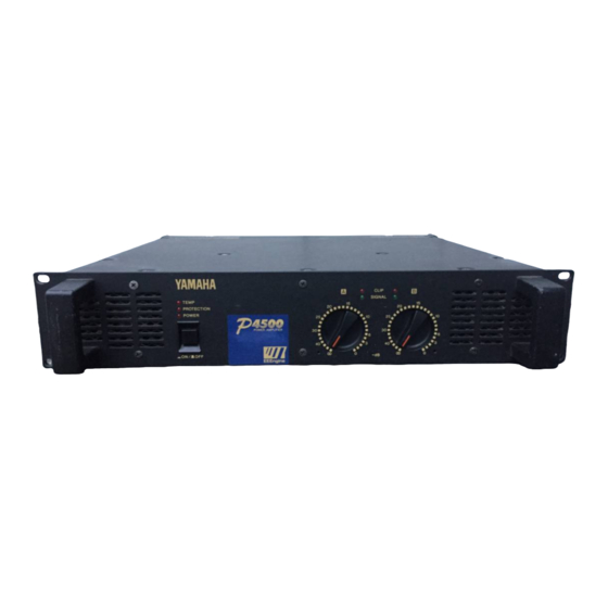
POWER AMPLIFIER Owner’s Manual Mode d’emploi Bedienungsanleitung Manual de instrucciónes CLIP SIGNAL TEMP PROTECTION POWER ∞ –dB ∞ EEEngine... - Page 2 • Variable-speed low-noise fan(s) ensures high reliability even under demanding conditions. This owner's manual covers the three models P4500, P3200 and P1600. In order to take full advantage of your power amp and enjoy long and trouble-free operation, please read this owner's manual carefully before use.
-
Page 3: Table Of Contents
4. Do not open the case or attempt repairs or modifica- tions yourself. This product contains no user-serviceable parts. Refer all maintenance to qualified Yamaha service personnel. Opening the case and/or tampering with the internal circuitry will void the warranty. -
Page 4: Controls And Functions
Controls and Functions Front Panel CLIP SIGNAL TEMP PROTECTION POWER ∞ –dB ∞ EEEngine 1 POWER switch and indicator 4 CLIP indicators This is the main POWER switch. Press to power ON the These red LED indicators light up when the respective amplifier. -
Page 5: Rear Panel
Rear Panel INPUT SPEAKERS (BRIDGE) CHANNEL B CHANNEL A CHANNEL B CHANNEL A (PARALLEL) (STEREO) 4-8Ω/SP BRIDGE (BRIDGE) 8-16Ω/SP STEREO BRIDGE STEREO PARALLEL MAX. OUTPUT 450W/4Ω (STEREO) MAX. OUTPUT 900W/8Ω (BRIDGE) 1 INPUT terminals (CHANNEL A, B) 3 SPEAKERS terminals Three types of balanced terminals for channels A and B For polarity in each mode, refer to the following dia- are provided. -
Page 6: Modes: Stereo/Parallel/Bridge
Modes: STEREO/PARALLEL/BRIDGE STEREO mode BRIDGE mode In this mode, channels A and B operate independently In this mode, the CHANNEL A input signal will be (as a conventional stereo amp). output from the BRIDGE output jacks. In this case, use The CHANNEL A input signal will be output from the the front panel (channel) volume control to adjust the... -
Page 7: Caution For Speaker Connection
W+460 W (8Ω) in stereo and 1240 W (8Ω) in monaural protective cover from the speaker terminals. on the P4500; 340 W+340 W (8Ω) in stereo and 880 W (8Ω) in monaural on the P3200; 160 W+160 W (8Ω) in stereo and 400 W (8Ω) in monaural on the P1600. -
Page 8: Rack Mounting
35% or more of the entire surface area of a 1U size panel to be open. Air circulation will be even better if the top surface of the rack has ventilation openings. Ventilation panel Yamaha provides an optional 1U-size ventilation panel VP1. Unit: mm Mounting four or fewer amps in... -
Page 9: Portable Rack Mounting
Portable Rack Mounting The amplifier intakes cool air through the front panel and exhausts warm air out the rear panel. When mounting amplifiers in a portable rack, make sure the rear panel is completely open for ventilation. (Side View) (Rear View) Front Completely open INPUT... -
Page 10: Specifications
Specifications General Specifications P4500 P3200 P1600 Power Output Level (Rated Power) 8Ω/STEREO 460 W + 460 W 340 W + 340 W 160 W + 160 W 20 Hz~20 kHz 4Ω/STEREO 620 W + 620 W 440 W + 440 W 200 W + 200 W 0.05%... -
Page 11: Block Diagram
Block Diagram SIGNAL Ach Power Amp CHANNEL A PC Limiter CHANNEL A (BRIDGE) (PARALLEL) CLIP Temperature PROTECTION Protection INPUT Sensor SPEAKERS Circuit TEMP (Heat Sink) CLIP CHANNEL B SIGNAL PARALLEL Bch Power Amp BRIDGE CHANNEL B STEREO PC Limiter Dimensions W:480 Unit: mm... -
Page 12: Performance Graphs
PROTECTION indicator amplifier. lights. A DC voltage of +/–2 V or Consult your dealer or greater was generated in the The relay operates to protect nearest Yamaha service power amplifier’s output the speaker system. center. circuit.