Sign In
Upload
Manuals
Brands
York Manuals
Chiller
YCAV0417V
York YCAV0417V Screw Compressor Chiller Manuals
Manuals and User Guides for York YCAV0417V Screw Compressor Chiller. We have
1
York YCAV0417V Screw Compressor Chiller manual available for free PDF download: Installation Operation & Maintenance
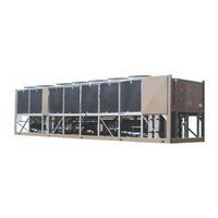
York YCAV0417V Installation Operation & Maintenance (350 pages)
AIR-COOLED SCREW LIQUID CHILLERS
Brand:
York
| Category:
Chiller
| Size: 21.2 MB
Table of Contents
Table of Contents
4
Section 1 - General Chiller Information & Safety
9
Introduction
9
Warranty
9
Safety
9
Standards for Safety
9
Responsibility for Safety
10
About this Manual
10
Misuse of Equipment
10
Suitability for Application
10
Structural Support
10
Mechanical Strength
10
General Access
10
Pressure Systems
11
Electrical
11
Rotating Parts
11
Sharp Edges
11
Refrigerant & Oils
11
High Temperature & Pressure Cleaning
11
Emergency Shutdown
11
Section 2 - Product Description
12
Introduction
12
General System Description
12
Compressor
13
Evaporator
14
Condensor
15
Flash Tank Feed / Drain Valve
15
Oil Separator/Oil System
15
Relief Valves
15
Oil Cooling
16
Capacity Controls
16
Power and Control Panel
16
Microprocessor & VSD Controls
16
Display
17
Keypad
17
Unit Switch
17
Variable Speed Drive (VSD)
18
Fig 1 - PWM Current Waveform
18
Fig 2 - PWM Voltage Waveform
18
Accessories & Options
19
Single Point Circuit Breaker
19
Building Automation System (BAS) Interface
19
Condensor Coil Protection
19
DX Cooler Options
20
Service Valve Option
20
Unit Enclosures
20
Fans
20
Sound Reduction Options
20
Vibration Isolation
20
Unit Nomenclature
21
Product Identification Number
22
Section 3 - Rigging, Handling and Storage
26
Delivery and Storage
26
Inspection
26
Lifting Weights
26
Moving the Chiller
27
Unit Rigging
28
Section 4 - Installation
28
Location Requirements
29
Outdoor Installation
29
Indoor Installation
29
Location Clearances
30
Vibration Isolators
30
Installation
30
Shipping Braces
30
Chilled Liquid Piping
30
General Requirements
30
Water Treatment
32
Connection Types & Sizes
32
Cooler Connections
32
Option Flanges
32
Fig 3 - Pipework Arrangement
32
Fig 4 - Victaulic Groove
32
Fig 5 - Flange Attachment
32
Refrigerant Relief Valve Piping
33
Ductwork Connection
33
General Requirements
33
Electrical Connection
33
Power Wiring
34
Vac Control Supply Transformer
34
Control Panel Wiring
34
Volts Free Contacts
35
Chilled Liquid Pump Starter
35
Run Contact
35
Alarm Contact
35
System Inputs
35
Flow Switch
35
Remote Run/Stop
35
Optional Remote Setpoint Offset Temp
35
Optional Remote Setpoint Offset Sound Limit
35
Section 5 - Commissioning
36
Preparation
36
Preparation - General
36
Inspection
36
Refrigerant Charge
36
Service and Oil Line Valves
36
Compressor Oil
36
Fans
36
Isolation / Protection
36
Control Panel
36
Power Connections
37
Grounding
37
Water System
37
Flow Switch
37
Temperature Sensor(S)
37
Programmed Options
37
Programmed Settings
37
Date & Time
37
Start / Stop
37
Setpoint & Remote Offset
37
Interlocks
38
Unit Switch
38
Start-Up
38
Oil Pressure
38
Refrigerant Flow
38
Loading
38
Suction Superheat
38
Subcooling
38
Condensor & Fan Rotation
39
General Operation
39
Section 6 - Technical Data
40
Water Pressure Drop Charts
40
Glycol Correction Factors
42
Water Temp. and Flows
43
Physical Data
44
Operating Limitations and
48
Sound Power
48
Electrical Data - Compr. Wiring
49
Fig 6 - Single Point Power Supply Connection
49
W/Circuit Breaker Protection (3 Compr)
49
Fig 7 - Single Point Power Supply Connection
49
W/Terminal Block (3 Compr)
49
W/Circuit Breaker Protection (4 Compr)
49
W/Terminal Block (4 Compr)
49
Fig 8 - Single Point Power Supply Connection
50
W/Circuit Breaker Protection (4 Compr)
50
Fig 9 - Single Point Power Supply Connection
50
W/Terminal Block (4 Compr)
50
Fig 10 - Multi-Point Power Supply Connection
51
Fig 11 - Multi-Point Power Supply Connection
51
Electrical Notes
60
Wiring Diagrams - 3 Compressor
62
Wiring Diagrams - 4 Compressor
74
Dimensions
90
Technical Data (Clearances)
156
Fig 12 - Sample Printout Supplied in the Isolator
157
Isolator Mounting
158
Package & Chiller Panel Literature Packet
158
Isolator Mounting Positions
159
Seismic Isolator Installation
163
Neoprene Isolator Position
164
Refrigerant Flow Diagram
167
Fig 13 - Refrigerant Flow Diagram
167
Diagram
168
Fig 14 - Processes and Instrumentation
168
Component Locations
169
Fig 15 - Component Locations
169
Fig 16 - Control and VSD Cabinet Locations
170
Fig 17 - Chiller Control Board, Relay Boards
171
Microgateway, and Optional Circuit Breaker
171
Microgateway
171
Fig 19 - VSD Logic Board
173
Fig 20 - VSD Logic Board
173
Fig 21 - Power Components
175
Fig 22 - Power Components
175
Fig 23 - Fan Contactors
177
Fig 24 - VSD Components
178
Fig 25 - VSD Components
179
Fig 26 - VSD Components
180
Fig 27 - VSD Components
181
Fig 28 - Inverter Power Components
182
Fig 29 - Inverter Power Components
183
Fig 30 - Inverter Power Components
184
Fig 31 - Inverter Power Components
184
Fig 32 - Glycol Pump & Fill Tube Locations
185
Fig 33 - Glycol Piping & Fill Tube Locations
186
Fig 34 - Compressor Components
187
Equipment Start-Up Check Sheet
188
Unit Checks (no Power)
188
Panel Checks
190
(Power ON-Both System Switches OFF)
190
Programmed Values
191
Chilled Liquid Setpoint
191
Date/Time, Daily Schedule, & Clock Jumper
191
Initial Start-Up
192
Check Subcooling & Superheat
192
Leak Checking
193
Chiller Electronic Components
194
Keypad
194
Display
195
Chiller Control Board
196
Relay Output Boards
197
VSD (Variable Speed Drive)
197
AC to DC Rectifier
197
SCR Trigger Board
198
DC Link Filter
198
1L Line Inductor
199
AC to DC Inverter
199
Laminated Bus Structure
199
VSD Logic Board
200
Control Panel to VSD Communications
200
IGBT Gate Driver Boards
201
Current Transformers
201
DV/DT Output Suppression Network
202
Flash Tank Feed/Drain Valve Controller
202
DC Bus Voltage Isolation Board
203
Chiller Circuit Breaker
203
Autotransformer
203
Chiller Configuration Jumpers
204
Number of Compr. Configuration Jumpers
204
Vsd Logic to Chiller Microprocessor
204
Board Rs-485 Communication
204
Configuration Jumpers
204
Table 1 - Compressors and the Appropriate Jumper
204
Positions
204
Table 2 - VSD Logic Board Address Jumper
204
Max Vsd Frequency
205
Table 3 - Maximum Frequency Jumper
205
Section 7 - Operation
206
Operating Controls
206
Basic Operating Sequence
208
Fig 35 - Chiller Control (Cooling) Range
208
Number of Compressors to Start
209
General
209
Standard IPLV
209
Optional Optimized IPLV
209
Fig 36 - Number of Compressors to Start
209
Minimum Vsd Compressor Start/Stop Frequency
210
Minimum VSD Start Frequency
210
Minimum VSD Run Frequency
210
Fig 37 - Minimum VSD Start Frequency
210
Fig 38 - Minimum VSD Run
210
Acceleration/Deceleration Rate
211
Compressors
211
VSD Acceleration/ Deceleration Rates
211
Standard Iplv Capacity Control
212
Fuzzy Logic Control
213
Hot Water Starts
214
Lag Compressor Operation in Load Limiting
214
Table 4 - Fuzzy Logic Loading/Unloading Vs. Error
214
Optional Iplv Capacity Control
215
Fuzzy Logic
216
Hot Water Starts
217
Table 5 - Fuzzy Logic Loading/Unloading Vs. Error
217
Load Limiting Control
218
Table 6 - Current Load Limiting/Unloading
218
Table 7 - Discharge Pressure Load Limiting
218
Unloading
218
Table 8 - Suction Pressure Load Limiting
219
Unloading
219
Table 9 - VSD Internal Ambient Load Limiting
219
Table 10 - VSD Baseplate Temperature Load
220
Limiting/Unloading
220
Controller
221
Valve Controller & Control Algorithm
221
Fig 39 - LED Locations
222
Fig 40 - Power, Comms Led's
223
Led's
223
Economizer Control
224
Condenser Fan Control
224
Table 11 - Fan Stages & Corresponding Outputs
225
Fig 42 - Standard IPLV Fan Control
226
Fig 43 - High IPLV Fan Control
226
Vsd Temperature Control/Fan Control Operation
227
Remote Temperature Reset Control
228
Local Current Limit Control
229
Pulldown Current Limit Setpoint
229
Remote Current Limit Reset
230
Sound Limit Controls
232
Vsd Operation & Controls
234
VSD Cooling and Cooling Loop
236
Table 12 - VSD Operating Display Parameters
239
Vsd Safeties
240
IGBT Gate Driver (Hardware) Fault
243
Power Supply (Hardware) Fault
245
Unit Warnings
248
Unit Safeties
252
System Safeties
254
Table 13 - Low Differential Oil Pressure Cutout
256
Table 14 - Start Inhibit Sensor Thresholds
258
Status Key
260
Unit Data Key
264
System Data Key
266
Table 15 - Sensor Min/Max Outputs
268
Vsd Data Key
270
Operating Hours & Start Keys
272
History Key
273
Unit Data
274
VSD Data
275
System Data
276
Compressor Operating Hours & Starts
278
Chilled Liquid & Cooling Setpoints
278
Options
278
Program Values
279
Setpoints Key
281
Table 16 - Setpoint Limits
282
Program Key
283
Table 17 - Programmable Operating Parameters
285
Options Key
286
Date/Time & Schedule Key
290
Date/Time Key
290
Schedule Key
291
Unit Operating Schedule
292
Sound Limit Schedule
293
Manual Override Key
294
Print Key
295
Table 18 - Printout Types
295
Operating Data Printout
296
History Data Printout
297
Service Key
298
System Switches Key
304
Serial Number Programming
305
Enabling Optimized High Iplv Mode
307
Unit Setup Mode
308
Table 19 - Unit Setup Programmable Values
308
Default Programmable Values
310
Serial Port Connections
311
Table 20 - Serial Port Connections
311
Analog Input Connections
312
Table 21 - Analog Input Connections
312
Digital Input Connections
314
Table 22 - Digital Input Connections
314
Analog Output Connections
316
Table 23 - Analog Output Connections
316
Digital Output Connections
318
Table 24 - Digital Output Connections
318
Isn Communications
320
Transmitted Data
320
Control Data
320
Table 26 - DXST/ISN Transmitted Data
321
Table 27 - Fault Inhibit Codes
325
Table 28 - Operational Status Codes
327
R-134A Conversion Tables
328
Table 29 - R-134A Pressure to Saturated
328
Temperature Conversion
328
Maintenance
329
General Requirements
329
Maintenance Requirements
330
Troubleshooting Guide
332
Evacuating a System
334
Warranty Policy
335
New Equipment
335
Reconditioned or Replacement Materials
335
All Warranties Are VIOD if
335
Chilled Liquid & Suction Temp Sensor Input Voltage Table
336
Table 30 - Temperature Input Voltage Sensor
336
Outside Air Temp Sensor Input Voltage Table
337
Table 31 - Outside Air Temperature Input Voltage
337
Pressure Transducer Output Voltage Table
338
Table 32 - Pressure Transducer Input Voltage
338
Motor Temperature Sensor Resistance Table
339
Maximum Vsd Frequency
340
Table 34 - Compressor Motor Overload Settings
340
Max. VSD Frequency
340
Printer Wiring
341
Fig 44 - Print Cable Chiller to Serial Printer
341
Okidata 184
342
Weigh-Tronix IMP Model 2600
342
Seiko
342
Operating Log
343
Site and Chiller Info
343
Programmed Values
343
Currents
344
System Operating Conditions
345
Water System Conditions
346
Condensor Conditions
346
Recommended Spare Parts
347
Advertisement
Advertisement
Related Products
York YCAV0417S
York YCAV0417P
York YCAV0417E
York YCAV0457S
York YCAV0457P
York YCAV0477S
York YCAV0477P
York YCAV0477E
York YCAV0477V
York YCAV0287E
York Categories
Air Conditioner
Heat Pump
Chiller
Furnace
Air Handlers
More York Manuals
Login
Sign In
OR
Sign in with Facebook
Sign in with Google
Upload manual
Upload from disk
Upload from URL