Sign In
Upload
Manuals
Brands
YOKOGAWA Manuals
Measuring Instruments
ScopeCorder DL750
YOKOGAWA ScopeCorder DL750 Manuals
Manuals and User Guides for YOKOGAWA ScopeCorder DL750. We have
3
YOKOGAWA ScopeCorder DL750 manuals available for free PDF download: User Manual, Operation Manual
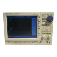
YOKOGAWA ScopeCorder DL750 User Manual (747 pages)
ScopeCorder
Brand:
YOKOGAWA
| Category:
Measuring Instruments
| Size: 24.97 MB
Table of Contents
Table of Contents
2
Contents
3
Product Registration
11
Contents
12
Manuals that Come with the DL750/DL750P
14
User's Manual Part 1
14
Checking the Contents of the Package
16
Standard Accessories
17
Safety Precautions
20
Functions Described in this Manual and the DL750/DL750P Version
24
Chapter 1 Names and Functions of Parts
28
Top Panel, Front Panel, Right Side Panel, and Left Side Panel
28
Front Panel
29
Right Side Panel
30
Panel Keys and Knobs
34
Display Screens
37
Chapter 2 Explanation of Functions
39
System Configuration/Block Diagram
39
Setting the Horizontal and Vertical Axes
41
Setting the Trigger
58
Setting Waveform Acquisition Conditions and Display Conditions
69
Recording in Recorder Mode (Realtime Recording) (DL750P Only)
81
Creating a PDF File of the Reprint Image (Only During T-Y Recording)
84
Waveform Computation
85
Waveform Analysis/Search
91
Communications
97
Other Useful Functions
99
Chapter 3 Making Preparations for Measurements
104
Handling Precautions
104
Installing the Instrument
106
Installing Input Modules
108
Connecting the Power Supply and Turning the Power Switch ON/OFF
111
Setting the Date and Time
116
Connecting Probes
118
Compensating the Probe (Phase Correction)
124
Connecting Measuring Leads
126
Connecting Thermocouples
127
Connecting a Bridge Head (Only on Strain Modules)
128
Connecting Logic Probes
131
Connecting Acceleration Sensors
133
Connecting Sensors to the Frequency Module
135
Connecting the Earphone Microphone with a PUSH Switch and Connecting the Speaker
136
Chapter 4 Common Operations
139
Operations and Functions of Keys and the Jog Shuttle
139
Entering Values and Strings
141
USB Keyboard/Usb Mouse
145
Initializing Settings
154
Performing Auto Setup
156
Performing Calibration
159
Using the Help Function
160
Chapter 5 Horizontal and Vertical Axes
161
Turning Channels ON/OFF
161
Setting T/DIV
162
Setting V/DIV
163
Setting the Vertical Position of Waveforms
165
Setting the Input Coupling
167
Setting the Probe Type
169
Setting the Bandwidth
170
Zooming Vertically by Setting the Zoom Rate
172
Zooming Vertically According to the Upper and Lower Limits of the Display Range
174
Setting the Offset Value
176
Using the Linear Scaling Function (AX+B, P1-P2)
178
Inverting Waveforms
181
Displaying the All Channel Setup Menu
182
Setting the Time Base (Internal Clock/External Clock)
185
Observing RMS Values
188
Setting the Strain Measurement
191
Setting the Acceleration Measurement
198
Frequency, Pulse Width, Pulse Integration, and Velocity) Measurement
200
Setting Logic Waveforms
215
Setting Event Waveforms
217
Chapter 6 Triggering
219
Setting the Trigger Mode
219
Setting the Trigger Position
221
Setting the Trigger Delay
223
Setting the Hold off Time
224
Setting the Edge Trigger (SIMPLE)
226
Setting the External Trigger (SIMPLE)
229
Generating Triggers on the Power Signal (SIMPLE)
230
Setting the Timer Trigger (SIMPLE)
231
Setting the Logic Trigger (SIMPLE)
233
Setting the a -> B(N) Trigger (ENHANCED)
235
Setting the a Delay B Trigger (ENHANCED)
238
Setting the Edge on a Trigger (ENHANCED)
241
Setting the or Trigger (ENHANCED)
245
Setting the B > Time, B < Time, or B Timeout (Pulse Width) Trigger (ENHANCED)
248
Setting the Period Trigger (ENHANCED)
252
Setting the Window Trigger (ENHANCED)
255
Setting the Wave Window Trigger (ENHANCED)
258
Setting the Action-On-Trigger
263
Setting Manual Triggers
266
Chapter 7 Acquisition and Display
267
Starting/Stopping Waveform Acquisition
267
Setting the Record Length
269
Setting the Acquisition Mode
271
Acquiring Data Using Box Average
274
Acquiring Data Using the Sequential Store Function (Single (N) Mode)
276
Using the Dual Capture Function
277
Realtime Recording to the Internal Hard Disk (Optional)
282
Setting the Action When Waveform Display Is Updated (Action-On-Stop)
286
Using the Voice Memo Function
289
Using the Acquisition Memory Backup Function
295
Chapter 8 Display
297
Changing the Display Format
297
Setting the Display Interpolation Method
299
Changing the Graticule
301
Accumulated Waveform Display
302
Zooming the Waveform
304
Displaying X-Y Waveforms
308
Using the Snapshot Function and Clear Trace Function
311
Turning Translucent Mode ON/OFF
312
Turning the Scale Value Display ON/OFF
313
Setting Waveform Labels
314
Turning the Extra Window ON/OFF
315
Turning the Level Indicator and Numeric Value Display ON/OFF
317
Displaying Channel Information/Displaying Waveforms on a Full Screen (Expanding the Waveform Area)
318
Chapter 9 Recording in Recorder Mode (Realtime Recording) (Only on the DL750P)
320
Loading the Roll Paper into the DL750P Built-In Printer
320
Selecting the Recorder Mode
323
Setting the Record Conditions of T-Y Waveform Recording
325
Setting the Recording Format of T-Y Waveform Recording
327
Recording T-Y Waveforms (T-Y Waveform Recording)
331
Recording Numeric Values
333
Recording X-Y Waveforms (X-Y Waveform Recording)
336
Reprinting on the Built-In Printer
340
Reprinting on the Built-In Printer
341
Creating a PDF File of the Reprint Image
345
User's Manual Part 1
352
Manuals that Come with the DL750/DL750P
352
Chapter 10 Waveform Computation
352
Adding, Subtracting, Multiplying, and Dividing Waveforms
358
Binary Computation
361
Performing Power Spectrum Computation (FFT)
364
Phase-Shifted Display
368
User-Defined Computation (Optional)
371
Chapter 11 Waveform Analysis/Search
380
Displaying History Waveforms
380
Searching History Memory Data Using Zones (History Search Function)
384
Searching History Memory Data Using Parameters (History Search Function)
388
Search Data Using Search and Zoom Function
390
Measuring Waveforms Using Cursors
396
Automated Measurement of Waveform Parameters
410
Performing Statistical Processing
417
Performing GO/NO-GO Determination Using Zones
423
GO/NO-GO Determination Using Measured Waveform Parameters
429
Using the GO/NO-GO Determination I/O Function
434
Output Signal
435
Chapter 12 Printing the Screen Image Data
436
Loading the Roll Paper and Paper Feeding
436
Printing on the Built-In Printer
439
Printing Screen Image Data to a USB Printer
449
Printing the Screen Image Data on a Network Printer
453
Chapter 13 Saving and Loading Data
455
Floppy Disks/Zip Disks/Pc Cards
455
Internal Hard Disk (Optional)
460
Connecting a USB Storage Device (MO Disk Drive, Hard Disk, or Flash Memory) to the USB PERIPHERAL Interface
461
Connecting a SCSI Device
463
Formatting the Storage Medium
464
Changing the SCSI ID Number
469
Saving/Loading the Waveform Data
471
Saving/Loading the Setup Data
480
Saving/Loading Snapshot Waveforms
485
Saving the Results of the Automated Measurement of Waveform Parameters
490
Saving Screen Image Data
492
Displaying Thumbnails of the Saved Screen Image Data
496
Creating PDF Files of the Printed Image (DL750P Only)
500
Loading/Converting Realtime Recorded Waveforms
507
Changing the File Attributes and Deleting Files
510
Copying Files
514
Changing the Directory/File Name of the Storage Medium and Creating Directories
518
Connecting a PC to the DL750/DL750P Via SCSI
521
Using the Voice Comment Function
524
Chapter 14 External Trigger I/O, External Clock Input, and Video Signal Output
527
External Trigger Input (TRIG IN)
527
Trigger Output (TRIG OUT)
528
External Clock Input (EXT CLK IN)
529
Video Signal Output (VIDEO out (SVGA))
530
External Start/Stop Input (GO/NO-GO)
532
Chapter 15 Using the DSP Channel (Optional)
533
DSP Channels (Optional)
533
Performing Addition, Subtraction, Multiplication, and Division (DSP Channels)
536
Using Filters (DSP Channels)
538
Performing Differentiation and Integration (DSP Channels)
542
Performing Addition, Subtraction, Multiplication, and Division with Coefficients (DSP Channels)
546
Using the Knocking Filter (DSP Channels)
548
Chapter 16 Ethernet Interface (Optional)
553
Connecting the DL750/DL750P to the Network
553
Connection Procedure
554
Setting up the TCP/IP
555
Saving/Loading Data to a Network Drive (FTP Client Function)
560
Setting up the Network Printer
564
Sending Periodic Mail or Action Mail
566
Accessing the DL750/DL750P from a PC or Workstation (FTP Server Function)
572
Using the Web Server Function
575
System Requirements
576
Setting the Time Difference from GMT (Greenwich Mean Time)/Sntp
600
Checking the Presence of the Ethernet Interface and the MAC Address
602
Setting the FTP Passive Mode and LPR/SMTP Timeout
603
Using the Instrument as a Windows Network Drive
604
Using the Instrument as a Windows Network Drive
605
Chapter 17 Other Operations
606
Changing the Menu/Message Language and Turning the Click Sound ON/OFF
606
Switching the Screen Display Font Size
607
Changing the USB Keyboard Language
608
Setting the Screen Color and Brightness
609
Turning off the Backlight and Setting the Brightness of the Backlight
611
Locking the Keys
612
Chapter 18 Troubleshooting, Maintenance, and Inspection
613
Troubleshooting
613
Messages and Corrective Actions
614
Error Message
614
Status Messages
614
Self-Diagnostic Test (Self Test)
625
Checking the System Conditions (Overview)
628
Recommended Replacement Parts
629
Chapter 19 Specifications
630
Input Section
630
Trigger Section
630
Time Axis
631
Display
632
Function
632
Data Storage
636
Built-In Printer
637
Storage
638
USB PERIPHERAL Interface
639
Auxiliary I/O Section
639
Computer Interface
642
General Specifications
643
Module Specifications
647
Logic Probe Specifications
670
External Dimensions
671
Appendix
674
Relationship between the Time Axis Setting, Sample Rate and Record Length
675
Appendix 2 Relationship between the Record Length and Acquisition Mode
678
Appendix 3 How to Calculate the Area of a Waveform
680
Appendix 4 ASCII Header File Format
682
Appendix 5 User-Defined Computation
687
Appendix 6 DSP Channel Computation (Optional)
696
Appendix 7 List of Defaults
719
Appendix 8 Assignment of Keys on the USB Keyboard
722
Appendix
722
Waveform Acquisition Operation When the Power Supply Recovers after a Power Failure
726
Appendix 10 Basic Defining Equation of Strain
727
Appendix 11 Shunt Calibration of the Strain Module
728
Appendix 12 Measurement Principles (Measurement Method and Update Rate) of the Frequency Module
733
Appendix 13 List of Preset Settings of the Frequency Module
737
Appendix 14 TCP and UDP Port Number Used in Ethernet Communications
739
Appendix 15 Relationship between the Chart Speed, Sample Rate, and Record Length During Recorder Mode
740
IM 701210-05/06E
741
Advertisement
YOKOGAWA ScopeCorder DL750 User Manual (406 pages)
Brand:
YOKOGAWA
| Category:
Voice Recorder
| Size: 10.61 MB
Table of Contents
User's Manual Part
5
User's Manual Part
7
Other Operations
8
Table of Contents
9
Chapter 10 Waveform Computation
17
Adding, Subtracting, Multiplying, and Dividing Waveforms
17
Binary Computation
20
Performing Power Spectrum Computation (FFT)
23
Phase-Shifted Display
27
User-Defined Computation (Optional)
30
Chapter 11 Waveform Analysis/Search
39
Displaying History Waveforms
39
Starting/Stopping Waveform Acquisition
41
Searching History Memory Data Using Zones (History Search Function)
43
Searching History Memory Data Using Parameters (History Search Function)
47
Search Data Using Search and Zoom Function
49
Measuring Waveforms Using Cursors
55
Using the Dual Capture Function
68
Automated Measurement of Waveform Parameters
69
Performing Statistical Processing
76
Performing GO/NO-GO Determination Using Zones
82
GO/NO-GO Determination Using Measured Waveform Parameters
88
Using the GO/NO-GO Determination I/O Function
93
Chapter 12 Printing the Screen Image Data
95
Loading the Roll Paper and Paper Feeding
95
Printing on the Built-In Printer
98
Printing Screen Image Data to a USB Printer
108
Printing the Screen Image Data on a Network Printer
112
Chapter 13 Saving and Loading Data
114
Floppy Disks/Zip Disks/Pc Cards
114
Internal Hard Disk (Optional)
119
Connecting a USB Storage Device (MO Disk Drive, Hard Disk, or Flash Memory) to the USB PERIPHERAL Interface
120
Connecting a SCSI Device
122
Formatting the Storage Medium
123
Changing the SCSI ID Number
128
Saving/Loading the Waveform Data
130
Saving/Loading the Setup Data
139
Saving/Loading Snapshot Waveforms
144
Saving the Results of the Automated Measurement of Waveform Parameters
149
Saving Screen Image Data
151
Displaying Thumbnails of the Saved Screen Image Data
155
Creating PDF Files of the Printed Image (DL750P Only)
159
Loading/Converting Realtime Recorded Waveforms
166
Changing the File Attributes and Deleting Files
169
Copying Files
173
Changing the Directory/File Name of the Storage Medium and Creating Directories
177
Connecting a PC to the DL750/DL750P Via SCSI
180
Using the Voice Comment Function
183
Connecting the Earphone Microphone with a PUSH Switch and Connecting the Speaker
183
Chapter 14 External Trigger I/O, External Clock Input, and Video Signal Output
186
External Trigger Input (TRIG IN)
186
Trigger Output (TRIG OUT)
187
External Clock Input (EXT CLK IN)
188
Video Signal Output (VIDEO out (SVGA))
189
External Start/Stop Input (GO/NO-GO)
191
Chapter 15 Using the DSP Channel (Optional)
192
DSP Channels (Optional)
192
Performing Addition, Subtraction, Multiplication, and Division (DSP Channels)
195
Using Filters (DSP Channels)
197
Performing Differentiation and Integration (DSP Channels)
201
Performing Addition, Subtraction, Multiplication, and Division with Coefficients (DSP Channels)
205
Using the Knocking Filter (DSP Channels)
207
Chapter 16 Ethernet Interface (Optional)
212
Connecting the DL750/DL750P to the Network
212
Setting up the TCP/IP
214
Entering Values and Strings
215
Saving/Loading Data to a Network Drive (FTP Client Function)
219
Using the Voice Memo Function
221
Setting up the Network Printer
223
Sending Periodic Mail or Action Mail
225
Accessing the DL750/DL750P from a PC or Workstation (FTP Server Function)
231
Using the Web Server Function
234
System Requirements
235
Setting the Time Difference from GMT (Greenwich Mean Time)/Sntp
259
Checking the Presence of the Ethernet Interface and the MAC Address
261
Setting the FTP Passive Mode and LPR/SMTP Timeout
262
Using the Instrument as a Windows Network Drive
263
Chapter 17 Other Operations
265
Changing the Menu/Message Language and Turning the Click Sound ON/OFF
265
Switching the Screen Display Font Size
266
Changing the USB Keyboard Language
267
Setting the Screen Color and Brightness
268
Turning off the Backlight and Setting the Brightness of the Backlight
270
Locking the Keys
271
Chapter 18 Troubleshooting, Maintenance, and Inspection
272
Troubleshooting
272
Messages and Corrective Actions
273
Error Message
273
Self-Diagnostic Test (Self Test)
284
Checking the System Conditions (Overview)
287
Recommended Replacement Parts
288
Chapter 19 Specifications
289
Input Section
289
Trigger Section
289
Time Axis
290
Display
291
Function
291
Setting the Trigger Mode
294
Built-In Printer
296
Storage
297
USB PERIPHERAL Interface
298
Auxiliary I/O Section
298
Computer Interface
301
General Specifications
302
Module Specifications
306
Logic Probe Specifications
329
External Dimensions
330
Appendix
333
Relationship between the Time Axis Setting, Sample Rate and Record Length
334
Appendix 2 Relationship between the Record Length and Acquisition Mode
338
Appendix 3 How to Calculate the Area of a Waveform
339
Appendix 4 ASCII Header File Format
344
Appendix 5 User-Defined Computation
352
Appendix 6 DSP Channel Computation (Optional)
356
Appendix 7 List of Defaults
378
Appendix 8 Assignment of Keys on the USB Keyboard
382
Appendix
383
Waveform Acquisition Operation When the Power Supply Recovers after a Power Failure
385
Appendix 10 Basic Defining Equation of Strain
386
Appendix 11 Shunt Calibration of the Strain Module
387
Appendix 12
392
Measurement Principles (Measurement Method and Update Rate) of the Frequency Module
392
Appendix 13 List of Preset Settings of the Frequency Module
396
Appendix 14 TCP and UDP Port Number Used in Ethernet Communications
398
Appendix 15 Relationship between the Chart Speed, Sample Rate, and Record Length During Recorder Mode
399
Accumulated Waveform Display
400
Initializing Settings
402
Recording Numeric Values
404
Turning Channels ON/OFF
405
Zooming Vertically by Setting the Zoom Rate
406
YOKOGAWA ScopeCorder DL750 Operation Manual (61 pages)
ScopeCorder
Brand:
YOKOGAWA
| Category:
Test Equipment
| Size: 1.85 MB
Table of Contents
Foreword
2
Table of Contents
3
Flow of DL750/DL750P Operation
4
Front Panel Controls
5
Parts of the Screen
7
Basic Key & Jog Shuttle Operations
9
Main Functions of the DL750/DL750P
11
Operating the DL750/DL750P
17
Making Preparations before Observing Waveforms
17
Displaying Waveforms on the Screen
19
Changing the Waveform Display Conditions
20
Changing the Trigger Setting
23
Measuring Waveforms
25
Zooming the Waveform Along the Time Axis
26
Printing/Saving Waveforms
27
Setup Menu Items
29
Setup (Cal)
29
CH1 to CH16 (LOGIC, EVENT, DSP)
30
Acq
37
All Ch
37
Simple/Enhanced
38
Mode (Action)
39
Position (Delay)
41
Dual Capture
42
Display (X-Y)
43
Measure (Go/No-Go)
45
Cursor
48
History
49
Math
50
Zoom (Search)
51
Voice Memo
54
Print
55
Image Save
56
File
56
RECORDER (Only DL750P)
57
Misc
59
Advertisement
Advertisement
Related Products
YOKOGAWA DL850 ScopeCorder
YOKOGAWA DL850V ScopeCorder
YOKOGAWA ScopeCorder DL750P
YOKOGAWA DY150
YOKOGAWA DY250
YOKOGAWA DX112
YOKOGAWA DX204
YOKOGAWA digitalYEWFLO DY20Q/R2
YOKOGAWA DTSXL
YOKOGAWA DX230P
YOKOGAWA Categories
Measuring Instruments
Test Equipment
Transmitter
Controller
Media Converter
More YOKOGAWA Manuals
Login
Sign In
OR
Sign in with Facebook
Sign in with Google
Upload manual
Upload from disk
Upload from URL