Sign In
Upload
Manuals
Brands
YOKOGAWA Manuals
Test Equipment
DL716
YOKOGAWA DL716 Manuals
Manuals and User Guides for YOKOGAWA DL716. We have
1
YOKOGAWA DL716 manual available for free PDF download: User Manual
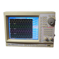
YOKOGAWA DL716 User Manual (255 pages)
Digital Scope
Brand:
YOKOGAWA
| Category:
Test Equipment
| Size: 3.98 MB
Table of Contents
Safety Precautions
6
Table of Contents
10
Chapter 1 Functions
14
Block Diagram
14
Setting the Vertical and Horizontal Axes
15
Setting a Trigger
20
Setting the Acquisition and Display Conditions
25
Analyzing the Waveform
32
Other Useful Functions
36
Chapter 2 Name and Use of each Part
38
Front Panel/Rear Panel
38
Operation Keys/Jog Shuttle/Knobs
40
Screens
43
Chapter 3 Before Starting Observation and Measurement of Waveforms
44
Precautions During Use
44
Installing
45
Connecting the Power Cord
47
Setting the Date and Time
49
Installing the Input Module
50
Connecting a Probe
52
Connecting a Input Cable
54
Connecting a Thermocouple
55
Connecting a Logic Probe
56
Compensating the Probe (Phase Correction)
58
Connecting the Bridge Head
59
Chapter 4 Common Operations
61
Entering Values and Character Strings
61
Initializing Settings
63
The Auto Set-Up Function
64
Starting and Stopping Acquisition
66
The Snapshot and Clear Trace Functions
68
Calibration
69
Using the Help Function
70
Selecting the Time Base
71
Chapter 5 Vertical and Horizontal Axes
73
Turning Channels ON/OFF
73
Setting T/DIV
74
Setting V/DIV
76
Setting the Vertical Position of a Waveform
77
Selecting Input Coupling
78
Selecting Probe Attenuation
79
Setting the Bandwidth
80
Zooming in Vertical Direction
82
Setting the Offset Voltage
83
Using the Linear Scaling Function
84
Inverting a Waveform
86
Setting the ON/OFF of Channels and the V/DIV with the All Channel Setting Menu
87
Setting the Temperature Measurement
88
Setting the Logic Probe
90
Setting the Strain Measurement
91
Using the Linear Scaling Function for the Strain
94
Displaying the Setup Menu over the Entire Screen (Full Screen Setup)
97
Chapter 6 Triggering
98
Setting the Trigger Mode
98
Selecting a Channel for Setting Trigger Hysteresis and Trigger Level
99
Setting Trigger Hysteresis for Channels 1 to 16
100
Setting the Trigger Level
101
Setting the Hold off Time
102
Setting the Trigger Position
103
Setting the Trigger Delay
105
Setting the Edge Trigger (SIMPLE)
106
Setting the A→B (N) Trigger (ENHANCED)
107
Setting the a Delay B Trigger (ENHANCED)
109
Setting the Edge on a Trigger (ENHANCED)
111
Setting the or Trigger (ENHANCED)
113
Setting the B>Time, B<Time or B Time out Trigger (ENHANCED)
114
Setting the Window Trigger (ENHANCED)
116
Setting the Timer Trigger
118
Chapter 7 Acquisition and Display
119
Setting the Record Length
119
Acquisition Mode
120
Sequential Store Mode
122
Box Average Mode
123
Using the History Memory
124
Realtime Print to the Built-In Printer
127
Realtime Record to the Internal Hard Disk (Optional)
129
Chapter 8 Display
132
Changing the Display Format
132
Setting the Interpolation Method
133
Changing the Graticule
135
Accumulated Waveform Display
136
Turning the Extra Window ON/OFF
138
Turning Display of the Scaling Value and Trigger Mark ON/OFF
139
Setting the Waveform Labels
140
X-Y Waveform Display
141
Zooming the Waveform
143
Scrolling the Waveform (Replay)
146
Chapter 9 Waveform Analysis
147
Measuring Waveforms Using Cursors
147
Automatic Measurement of Waveform Parameters
150
Setting Computing Range and Display Units, and Recomputing
155
Waveform Addition, Subtraction and Multiplication
156
Binary Computation
157
Phase Shifted Addition, Subtraction and Multiplication
159
Simultaneous Binary Computation and D/A Conversion of All Channels
161
Displaying Power Spectrums
163
Manual Scaling
164
Executing User Defined Computation (Optional)
165
Chapter 10 Output of Screen Data
170
Loading Paper Roll in Printer
170
Feeding the Chart
172
Outputting to Printer
173
Outputting to a Printer with a Centronics Interface
175
GP-IB/RS-232 Interface : Data Output and Format Selection
177
Outputting to Floppy Disk, Internal Hard Disk (Optional) or External SCSI Device
181
Chapter 11 Saving/Loading the Data/Connecting to the PC
183
Floppy Disks
183
Internal Hard Disk (Optional)
184
Connecting a SCSI Device
185
Formatting Disks
186
Selecting the Medium and Directory
189
Saving/Loading Waveform Data
190
Saving/Loading Set-Up Data
193
Saving Waveform Data in ASCII, Binary or AG Series Format
195
Deleting Files
197
Copying Files
198
Saving Automatic Measurement Results
199
Changing the SCSI Ids
200
Connecting to a PC
201
Chapter 12 External Trigger Input/Output, Video Signal Output
204
External Trigger Input (TRIG IN)
204
Trigger Output (TRIG OUT)
205
Video Signal Output (VIDEO OUT)
206
Chapter 13 Other Operations
207
Setting the Screen Color
207
Setting the Message Language, Click Sound and Brightness of the LCD
209
Setting the Screen Saver Function
210
Setting the Action on Trigger
211
Locking the Keys
213
ON/OFF the Backlight
214
Chapter 14 Troubleshooting, Maintenance and Inspection
215
Breakdown Troubleshooting
215
Error Messages and Corrective Actions
216
Self-Diagnostic Test (Self Test)
219
Checking the System Condition
221
Warranties on Parts
222
Chapter 15 Specifications
223
Input Section
223
Trigger Section
223
Time Axis
224
Display
224
Functions
224
External Trigger Input/Output, Video Signal Output
226
GP-IB Interface
226
Interface
226
Centronics Interface
226
SCSI Interface
227
Built-In Printer
227
Built-In Floppy Disk Drive
227
Internal Hard Disk (Optional)
227
32-Bits Extended Logic Input (Optional)
228
GO/NOGO Input/Output
228
General
229
External Dimensions
230
High-Speed Isolation Module (701855)
231
High-Speed Module (701856)
232
High-Resolution, High-Voltage, Isolation Module (701852)
233
High-Resolution, Isolation Module (701853)
234
Temperature Module (701860)
235
Logic Input Module (701870)
236
Strain Module (701880)
237
Appendix
238
Appendix 1 Relationship between the Time Axis Setting, Sample Rate and Record Length
238
Appendix 2 Relationship between the Record Length and Acquisition Mode
240
Appendix 3 How to Calculate the Area of a Waveform
241
Appendix 4 ASCII Header File Format
244
Appendix 5 List of Defaults
245
Appendix 6 about User Defined Computations
246
Appendix 7 for Input Module 701850 and 701851
251
Index
253
Advertisement
Advertisement
Related Products
YOKOGAWA DL7440
YOKOGAWA DL7480
YOKOGAWA DL7200
YOKOGAWA DL7400
YOKOGAWA DL 1540
YOKOGAWA DL 1520
YOKOGAWA DL9240L
YOKOGAWA DL9000 Series
YOKOGAWA DL1640
YOKOGAWA DL1640L
YOKOGAWA Categories
Measuring Instruments
Test Equipment
Transmitter
Controller
Media Converter
More YOKOGAWA Manuals
Login
Sign In
OR
Sign in with Facebook
Sign in with Google
Upload manual
Upload from disk
Upload from URL