Sign In
Upload
Manuals
Brands
Yanmar Manuals
Engine
4TNV88-B
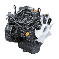
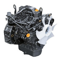
Yanmar 4TNV88-B Industrial Diesel Engine Manuals
Manuals and User Guides for Yanmar 4TNV88-B Industrial Diesel Engine. We have
3
Yanmar 4TNV88-B Industrial Diesel Engine manuals available for free PDF download: Service Manual, Troubleshooting Manual, Operation Manual
Yanmar 4TNV88-B Service Manual (394 pages)
Industrial
Brand:
Yanmar
| Category:
Engine
| Size: 29.06 MB
Table of Contents
Table of Contents
5
Proposition 65 Warning
2
Yanmar Warranties
9
Yanmar Warranties
10
Yanmar Limited Warranty
11
How Long Is the Warranty Period
11
What Is Covered by this Warranty
11
What the Engine Owner Must Do
11
To Locate an Authorized Yanmar Industrial Engine Dealer or Distributor
12
What Is Not Covered by this Warranty
12
What Yanmar will Do
12
Questions
13
Retail Purchaser Registration
13
Warranty Limitations
13
Warranty Modifications
13
Dealer or Distributor
12
Emission System Warranty
14
Yanmar Co., Ltd. Limited Emission Control System Warranty - USA Only
14
Manufacturer's Warranty Period
14
Your Warranty Rights and Obligations
14
Warranted Parts
15
Warranty Coverage
15
Turbocharger
15
Exclusions
16
Owner's Warranty Responsibilities
16
Safety
17
Periodic Maintenance
19
Fuel System
20
Alternator
29
Starter Motor
30
General Service Information
33
Electric Wiring
36
General Service Information
41
Cooling System
41
Component Identification
43
Location of Labels
45
Engine Nameplate (Typical)
46
Emission Control Regulations
46
EPA / ARB Regulations - USA Only
46
Emission Control Labels
46
The 97/68/EC Directive Certified Engines
47
Engine Family
47
Function of Major Engine Components
48
Main Electronic Control Components and Features
49
Function of Cooling System Components
51
Diesel Fuel
52
Diesel Fuel Specifications
52
Filling the Fuel Tank
53
Priming the Fuel System
55
Engine Oil
55
Engine Oil Specifications
55
Checking Engine Oil
56
Engine Oil Viscosity
56
Adding Engine Oil
57
Engine Oil Capacity (Typical)
57
Engine Coolant
58
Engine Coolant Specifications
59
Filling Radiator with Engine Coolant
59
Engine Coolant Capacity (Typical)
60
Specifications
61
Description of Model Number
61
Engine Speed Specifications
61
Engine General Specifications
62
Principal Engine Specifications
63
3TNV82A (~ EPA Tier2)
63
3TNV84 (~ EPA Tier2)
64
3TNV84T (~ EPA Tier2)
65
3TNV88 (~ EPA Tier2)
66
4TNV84 (~ EPA Tier2)
67
4TNV84T (~ EPA Tier2)
68
4TNV88 (~ EPA Tier2)
69
4TNV94L (~ EPA Tier2)
70
4TNV98 (~ EPA Tier2)
71
4TNV98T (~ EPA Tier2)
72
4TNV106 (~ EPA Tier2)
73
4TNV106T (~ EPA Tier2)
74
3TNV82A-B (Complies with EPA Interim Tier4)
75
3TNV84T-B (Complies with EPA Interim Tier4)
76
3TNV88-U (Complies with EPA Interim Tier4)
77
3TNV88-B (Complies with EPA Interim Tier4)
78
4TNV84T-Z (Complies with EPA Interim Tier4)
79
4TNV88-U (Complies with EPA Interim Tier4)
80
4TNV88-B (Complies with EPA Interim Tier4)
81
4TNV98-E (Complies with EPA Interim Tier4)
82
4TNV98-Z (Complies with EPA Interim Tier4)
83
4TNV98T-Z (Complies with EPA Tier3)
84
Engine Service Standards
85
Tightening Torques for Standard Bolts and Nuts
86
Abbreviations and Symbols
88
Abbreviations
88
Symbols
88
Unit Conversions
89
Unit Prefixes
89
Units of Force
89
Units of Length
89
Units of Mass
89
Units of Power
89
Units of Pressure
89
Units of Temperature
89
Units of Torque
89
Units of Volume
89
Periodic Maintenance
91
Before You Begin Servicing
93
Introduction
106
The Importance of Periodic Maintenance
106
Performing Periodic Maintenance
106
Yanmar Replacement Parts
106
Required EPA / ARB Maintenance -USA Only
106
EPA / ARB Installation Requirements - USA Only
106
Periodic Maintenance Schedule
107
Periodic Maintenance Procedures
110
After Initial 50 Hours of Operation
110
Every 50 Hours of Operation
114
Every 250 Hours of Operation
117
Every 500 Hours of Operation
122
Every 1000 Hours of Operation
126
Every 1500 Hours of Operation
129
Every 2000 Hours of Operation
132
Engine
133
Before You Begin Servicing
135
Cylinder Head Specifications
138
Adjustment Specifications
138
Cylinder Head
138
Intake / Exhaust Valve and Guide
139
Push Rod
141
Rocker Arm and Shaft
141
Valve Spring
142
Introduction
138
Camshaft and Timing Gear Train Specifications
143
Camshaft
143
Idler Gear Shaft and Bushing
145
Timing Gear Backlash
145
Crankshaft and Piston Specifications
146
Crankshaft
146
Thrust Bearing
147
Piston
148
Piston Ring
150
Connecting Rod
154
Tappet
155
Cylinder Block Specifications
156
Cylinder Block
156
Special Torque Chart
157
Torque for Bolts and Nuts
157
Special Service Tools
160
Measuring Instruments
164
2-Valve Cylinder Head
166
2-Valve Cylinder Head Components
166
Components of a Two-Valve Cylinder Head
167
Disassembly of 2-Valve Cylinder Head
168
Cleaning of Cylinder Head Components
172
Inspection of Cylinder Head Components
172
Reassembly of Cylinder Head
176
4-Valve Cylinder Head
181
4-Valve Cylinder Head Components
181
Disassembly of 4-Valve Cylinder Head
182
Cleaning of Cylinder Head Components
187
Inspection of Cylinder Head Components
188
Reassembly of Cylinder Head
193
Measuring and Adjusting Valve Clearance
198
2-Valve Cylinder Heads
199
4-Valve Cylinder Heads
200
Crankshaft and Camshaft Components
203
Disassembly of Engine
204
Disassembly of Camshaft and Timing Components
205
Disassembly of Crankshaft and Piston Components
210
Inspection of Crankshaft and Camshaft Components
214
Honing and Boring
220
Reassembly of Crankshaft and Piston Components
221
Reassembly of Camshaft and Timing Components
227
Final Reassembly of Engine
231
EGR System
232
Inspecting/Cleaning EGR Related Components
237
Fuel System
241
Before You Begin Servicing
243
Introduction
248
Fuel Injection Pump
248
Cold Start Device
249
Stop Solenoid
249
Electronically Controlled Governor
250
Trochoid Fuel Pump
250
Fuel System Specifications
251
Special Torque Chart
251
Test and Adjustment Specifications
252
Measuring Instruments
253
Special Service Tools
253
Fuel System Diagram
254
2 Valve Cylinder Head
255
Fuel System Components
255
4 Valve Cylinder Head
257
Fuel Injection Pump
259
Removal of Fuel Injection Pump
259
Installation of Fuel Injection Pump
264
Checking and Adjusting Fuel Injection Timing
270
Determining the Fuel Injection Timing Specification
270
Checking Fuel Injection Timing
271
Adjusting Fuel Injection Timing
274
Fuel Injectors
275
Removal of Fuel Injectors
275
Testing of Fuel Injectors
278
Disassembly and Inspection of Fuel Injectors
279
Adjusting Fuel Injector Pressure
281
Reassembly of Fuel Injectors
281
Installation of the Fuel Injectors
282
Cooling System
285
Before You Begin Servicing
287
Cooling System Diagram
290
Introduction
290
Engine Coolant Pump Components
291
Engine Coolant Pump
292
Removal of Engine Coolant Pump
292
Disassembly of Engine Coolant Pump
294
Cleaning and Inspection
294
Reassembly of Engine Coolant Pump
295
Installation of Engine Coolant Pump
296
Engine Coolant System Check
292
Lubrication System
299
Before You Begin Servicing
301
Introduction
303
Oil Pump Service Information
304
Lubrication System Diagram
306
Checking Engine Oil Pressure
307
Trochoid Oil Pump
307
3TNV82A to 4TNV88 Oil Pump Components
307
Disassembly of Oil Pump
308
Cleaning and Inspection
309
Reassembly of Oil Pump
310
Trochoid Oil Pump
311
3Tnv82A-B, 3Tnv88-B, 3Tnv88-U, 4Tnv88-B4Tnv88-U
311
3TNV84T-Z, 4TNV84T-Z Oil Pump Components
311
Disassembly of Oil Pump
312
Cleaning and Inspection
312
Reassembly of Oil Pump
314
4 TNV94L/98/106 Oil Pump Components
315
Trochoid Oil Pump
315
Disassembly of Oil Pump
315
Cleaning and Inspection
316
Reassembly of Oil Pump
317
Turbocharger
319
Before You Begin Servicing
321
Introduction
323
Specifications
323
Turbocharger Service Information
323
Troubleshooting
324
Excessive Exhaust Smoke
324
Generates White Smoke
325
Sudden Oil Decrease
325
Decrease in Output
325
Poor (Slow) Response (Starting) of Turbocharger
325
Abnormal Sound or Vibration
325
Turbocharger Components
326
Turbocharger Component Functions
328
Theory of Operation
329
Compressor Side Sealing Mechanism
329
Waste Gate Modulation
329
Washing Procedure
330
Periodic Inspection
331
Visual Inspection
331
Inspection of Rotor Rotation
331
Inspection of Rotor Play
331
Removal of Turbocharger
331
Checking Rotor Play
332
Waste Gate Valve Test
332
Waste Gate Actuator Leak Test
333
Installation of Turbocharger
333
Starter Motor
335
Before You Begin Servicing
337
Introduction
339
Starter Motor Information
339
3TNV82A to 4TNV88 - Standard and Optional
339
Starter Motor Specifications
341
Starter Motor Troubleshooting
342
Starter Motor Components
343
Starter Motor
344
Removal of Starter Motor
344
Disassembly of Starter Motor
344
Cleaning and Inspection
346
Reassembly of Starter Motor
351
Check Pinion Projection Length
352
No-Load Test
353
Installation of Starter Motor
354
Alternator
355
Before You Begin Servicing
357
Dynamo and Alternator Information
360
3TNV82A to 4TNV106T - Standard and Optional Dynamos
360
3TNV82A to 4TNV106T - Standard and Optional Alternators
360
Introduction
360
Alternator Specifications
361
Dynamo Specifications
361
Alternator Troubleshooting
362
Alternator Components
363
Alternator Wiring Diagram
364
Alternator Standard Output
365
Alternator
366
Removal of Alternator
366
Disassembly of Alternator
366
Reassembly of Alternator
368
Installation of Alternator
370
Dynamo Component Location
371
Dynamo Wiring Diagram
372
Operation of Dynamo
372
Dynamo Standard Output
373
Testing of Dynamo
374
Testing Stator Coil Continuity
374
Testing Stator Coil Short-To-Ground
374
Testing Dynamo Regulated Output
374
Engines Available with the Electronic Control System
379
Before You Begin Servicing
379
Introduction
381
Electronic Control System
381
Electronic Control Harness Connections
382
Electric Wiring Precautions
387
Electrical Wire Resistance
388
Battery Cable Resistance
389
Electrical Wire Sizes - Voltage Drop
390
Conversion of AWG to European Standards
391
Advertisement
Yanmar 4TNV88-B Troubleshooting Manual (235 pages)
ELECTRONIC CONTROL
Brand:
Yanmar
| Category:
Engine
| Size: 9.52 MB
Table of Contents
Proposition 65 Warning
2
Table of Contents
3
DTC Code List
5
Description Items
9
DTC Detecting Conditions
9
Estimation of Failure Cause/Error Condition
9
Movement at Error Occurrence
9
Analog Input Related Failures
10
P1202/4: Failure with Rack Position Sensor (Low Voltage)
10
Rack Position Sensor
10
P1203/3: Failure with Rack Position Sensor (High Voltage)
12
P0122/4: Accelerator Sensor Error (Low Voltage)
14
P0123/3: Accelerator Sensor Error (High Voltage)
16
P0124/2: Intermittent Failure with Accelerator Sensor
18
P0123/1: Accelerator Sensor Error (Foot Pedal-Close Position)
20
P1126/0: Accelerator Sensor Error (Foot Pedal-Open Position)
22
P0222/4: Failure with Spare Accelerator Sensor (Low Voltage)
24
P0223/3: Spare Accelerator Sensor Error (High Voltage)
26
P0224/2: Intermittent Failure with Spare Accelerator Sensor
28
P1225/1: Spare Accelerator Sensor Error (Foot Pedal-Close Position)
30
P1226/0: Spare Accelerator Sensor Error (Foot Pedal-Open Position)
32
P1227/8: Failure with Spare Accelerator Sensor (Pulse Communication)
34
Atmospheric Pressure Sensor (Option)
36
P2228/4: Failure with Atmospheric Pressure Sensor (Low Voltage)
36
P2229/3: Failure with Atmospheric Pressure Sensor (High Voltage)
38
P2230/2: Intermittent Failure with Atmospheric Pressure Sensor
40
ECU Temperature Sensor
42
P0668/4: Failure with ECU Temperature Sensor (Low Voltage)
42
P0669/3: Failure with ECU Temperature Sensor (High Voltage)
43
P1664/2: Intermittent Failure with ECU Temperature Sensor
44
P0634/0: ECU Temperature Rise Alarm
45
Cooling Water Temperature Sensor
47
P0117/4: Failure with Cooling Water Temperature Sensor (Low Voltage)
47
P0118/3: Failure with Cooling Water Temperature Sensor (High Voltage)
49
P0119/2: Intermittent Failure with Cooling Water Temperature Sensor
51
P0217/0: Cooling Water Temperature Rise Alarm
53
P0642/4: Failure with SENSOR 5V (Low Voltage)
55
Sensor 5V
55
P0643/3: Failure with SENSOR 5V (High Voltage)
56
P1644/2: Intermittent Failure with SENSOR 5V
57
P0562/1: Power Supply Voltage Error (Low Voltage)
58
P0563/0: Power Supply Voltage Error (High Voltage)
60
P0340/4: Failure with Speed Sensor
62
Pulse Sensor Related Failures
62
P1340/4: Failure with Spare Speed Sensor
64
Spare Speed Sensor (Option)
64
Engine Rotational Speed
66
P0219/0: over Speed Error
66
Contact Output Related Failures
68
P1222/4: Failure a with Rack Actuator Relay
68
Rack Actuator Relay
68
P1223/3: Failure B with Rack Actuator Relay
70
P1224/2: Intermittent Failure with Rack Actuator Relay
72
P1232/4: Failure a with Start Assist Relay
74
Start Assist Relay
74
P1233/3: Failure B with Start Assist Relay
76
P1234/2: Intermittent Failure with Start Assist Relay
78
CSD Solenoid Valve
80
P1242/4: Failure a with CSD Solenoid Valve
80
P1243/3: Failure B with CSD Solenoid Valve
82
P1244/2: Intermittent Failure with CSD Solenoid Valve
84
EGR Valve
86
P1402/4: Failure a with EGR Valve (Step Motor A-Phase)
86
P1403/3: Failure B with EGR Valve (Step Motor A-Phase)
88
P1412/4: Failure a with EGR Valve (Step Motor B-Phase)
90
P1413/3: Failure B with EGR Valve (Step Motor B-Phase)
92
P1422/4: Failure a with EGR Valve (Step Motor C-Phase)
94
P1423/3: Failure B with EGR Valve (Step Motor C-Phase)
96
P1432/4: Failure a with EGR Valve (Step Motor D-Phase)
98
P1433/3: Failure B with EGR Valve (Step Motor D-Phase)
100
Contact Input Related Failures
102
Oil Pressure Related Failures
102
P1192/4: Failure with Oil Pressure Switch
102
P1198/1: Abnormal Oil Pressure Descend
104
Battery Charge Related Failures
106
P1562/4: Failure with Charge Switch
106
P1568/1: Charge Alarm
108
P1217/0: Abnormal Water Temperature
110
Water Temperature Switch
110
Air Cleaner Switch
112
P1101/0: Air Cleaner Clogging Alarm
112
Oil-Water Separator Switch
114
P1151/0: Oil-Water Separator Alarm
114
Actuators Etc.
116
P1212/4: Failure with Rack Actuator (Low Current)
116
Rack Actuator
116
P1212/3: Failure with Rack Actuator (High Current)
118
P1211/7: Rack Actuator Mechanical Failure
120
Engine
122
P1214/2: Engine Trouble
122
E-ECU Internal and Communication Errors
124
E-ECU Internal Errors
124
P0601/12, P1610/12, P1611/12, P1612/12: ECU Internal Errors
124
P1601/2, P0605/12, P1605/2, P1606/2, P1620/12: ECU Internal Errors
125
P0686/4: Main Relay Error
126
CAN Communication
128
U0001/12: CAN Communication Error
128
U0167/12: Immobilizer Error (CAN Communication)
130
U1167/8: Immobilizer Error (Pulse Communication)
132
U0426/2: Immobilizer Error (System)
134
Method and Procedure of Failure Diagnosis
135
Description Items
135
E-ECU Pin Layout Diagram
136
Harness Side Coupler (Coupling Face)
136
ECU Side Coupler (Coupling Face)
136
How to Use the 2G Eco-Checker Harness
137
Related DTC
138
Analog Input Related Failures
138
Wiring Diagram
139
Diagnosis Description
140
Check of Harness Continuity
140
Accelerator Sensor
142
Work Description
144
Foot Pedal
146
Pulse Accelerator
154
View of the Sensor
159
Characteristics of Cooling Water Temperature Sensor
160
Pulse Sensor Related Failures
166
Contact Output Related Failures
172
CSD Solenoid Valve Coil
180
Contact Input Related Failures
189
Actuator Related Failures
195
ECU Internal and Communication Errors
199
ECU Internal Errors
199
Main Relay
201
Immobilizer
207
Failure Indicator Lamp Flashing Pattern
209
Using the Failure Indicator for Failure Diagnosis
210
Flashing Patterns of the Failure Indicator
210
Factor Analysis
212
2G-Type Eco-Governor Speed-Fluctuation Factor Analysis
212
2G-Type Eco-Governor Engine
215
Type Eco-Governor Engine Stalling/Start-Up Inability Factor Analysis
215
2G-Type Eco-Governor Black Smoke Factor Analysis
218
Special Service Tools
220
Troubleshooting by Measuring Compression Pressure
221
Compression Pressure Measurement Method
221
Standard Compression Pressure (Reference Value)
223
Engine Speed and Compression Pressure (Use for Reference)
223
Measured Value and Troubleshooting
224
Quick Reference Table for Troubleshooting
224
Failure Diagnostic List
225
Electrical Wiring
231
Yanmar 4TNV88-B Operation Manual (164 pages)
TNV series
Brand:
Yanmar
| Category:
Engine
| Size: 11.02 MB
Advertisement
Advertisement
Related Products
Yanmar 4TNV84T-Z
Yanmar 4TNV84
Yanmar 4TNV84T
Yanmar 4TNV88
Yanmar 4TNV88-U
Yanmar 4TNV88-Z
Yanmar 4TNV84T-B
Yanmar 4TNV94L
Yanmar 4TNV98T
Yanmar 4 TNV Series
Yanmar Categories
Engine
Tractor
Portable Generator
Outboard Motor
Excavators
More Yanmar Manuals
Login
Sign In
OR
Sign in with Facebook
Sign in with Google
Upload manual
Upload from disk
Upload from URL