Sign In
Upload
Manuals
Brands
Yanmar Manuals
Engine
4JH2E
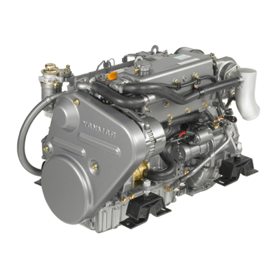
Yanmar 4JH2E Marine Diesel Engine Manuals
Manuals and User Guides for Yanmar 4JH2E Marine Diesel Engine. We have
2
Yanmar 4JH2E Marine Diesel Engine manuals available for free PDF download: Service Manual
Yanmar 4JH2E Service Manual (407 pages)
Marine Diesel Engine
Brand:
Yanmar
| Category:
Engine
| Size: 11.94 MB
Table of Contents
History of Revision
3
Table of Contents
5
General/Table of Contents
6
Exterior Views 4JH2E
7
Exterior Views 4JH2E-TE
8
Exterior Views 4JH2E-HTE/DTE/UTE
9
Marine Gear
10
Applicability of Marine Gear and Reduction Ratio
10
Construction
12
4JH2E Performance Curves
13
4JH2E-TE Performance Curves
14
4JH2E-HTE Performance Curves
15
4JH2E-DT (B) E Performance Curves
16
4JH2E-UTE Performance Curves
17
Engine Cross Section
18
4JH2E X KM3P2 Dimensions
19
4JH2E X KBW20 Dimensions
20
4JH2E X KBW21 Dimensions
21
4JH2E-TE X KM4A Dimensions
22
4JH2E-TE X KBW20 Dimensions
23
4JH2E-HTE X KM4A Dimensions
24
4JH2E X KM4A Dimensions
25
4JH2E-DTE X KM4A Dimensions
26
4JH2E-DTE X KBW21 Dimensions
27
4JH2E-UTE X KW4A Dimensions
28
4JH2E-UTE X KBW21 Dimensions
29
Piping Diagram 4JH2E
30
Piping Diagram 4JH2E-TE
31
Piping Diagram 4JH2E-HTE/DTE/UTE
32
Inspection Ans Servicing of Basic Engine Parts/Table of Contents
33
Cylinder Block
34
Inspection of Parts
34
Cleaning of Oil Holes
34
Color Check Procedure
34
Replacement of Cup Plugs
35
Cylinder Bore Measurement
36
Cylinder Head
39
Inspecting the Cylinder Head
40
Distortion of the Combustion Surface
40
Checking for Cracks in the Combustion Surface
40
Checking the Intake and Exhaust Valve Seats
40
Valve Seat Correction Procedure
41
Wearing and Corrosion of Valve Stem
41
Inspection of Valve Seat Wear and Contact Surface
42
Valve Sinking/Guide
42
Checking Valve Springs
43
Assembling the Cylinder Head
44
Measuring Top Clearance
44
Intake and Exhaust Valve Arms
44
Adjustment of Valve Head Clearance
45
Piston and Piston Pins
46
ID Mark for Piston
46
Over Size Piston and Ring COMP
46
Piston Head and Combustion Surface
47
Measurement of Piston Outside Diameter/Inspection
47
Replacing the Piston
47
Piston Rings
48
Measuring the Rings
48
Measuring Piston Ring Gap
48
Replacing the Piston Rings
49
Inspecting the Connecting Rod
50
Twist and Parallelism of the Large and Small Ends
50
Checking Thrust Clearance
50
Checking Crank Pin Bushing
51
Measuring Crank Pin Oil Clearance
51
Precautions on Replacement of Crank Pin Bushing
51
Piston Pin Bushing
51
Assembling Piston and Connecting Rod
52
Crankshaft
53
Color Check of Shaft
53
Bending of the Crankshaft
54
Measuring the Crank Pin and Journal
54
Checking Side Clearance of the Crankshaft
55
Inspecting the Main Bearing
55
Measuring the Inner Diameter of Metal
55
Camshaft
56
Tappets
57
Timing Gear
59
Inspecting the Gears
59
Gear Timing Marks
60
Specifications of Flywheel
61
Dimensions of Flywheel and Mounting Flange
62
Ring Gear
63
Position of Top Dead Center and Fuel Injection Timing
63
Damper Disc and Cooling Fan
64
Applicability of Cooling Fan
64
Fuel Injection Equipment/Table of Contents
65
Fuel Injection Pump Service Data
66
Governor
67
Boost Compensator
67
Diassembly, Reassembly and Inspection of Governor
69
Governor Disassembly
70
Inspection of Governor
74
Assembling Governor
74
Disassembly, Reassembly and Inspection of Fuel Injection Pump
78
Disassembly of Fuel Injection Pump
79
Inspection of Fuel Injection Pump
83
Reassembly of Fuel Injection Pump
84
Adjustment of Fuel Injection Pump and Governor
88
Adjustment of Top Clearance
89
Adjusting of Injection Timing
90
Plunger Pressure Test
91
Delivery Valve Pressure Test
91
Measuring/Adjustment of Injection Volume
91
Adjusting Fuel/Rpm Limit Bolt
92
Adjusting Idling
92
Check Injection Volume When Starting
93
Construction of Fuel Feed Pump
94
Fuel Feed Pump Specifications
94
Disassembly and Reassembly of Fuel Feed Pump
95
Fuel Feed Pump Inspection
95
Functioning of Fuel Injection Nozzle
96
Fuel Injection Nozzle Disassembly/Inspection
97
Fuel Injection Nozzle Reassembly
98
Nozzle Inspection
98
Adjusting Opening Pressure
99
Injection Test
99
Troubleshooting of Fuel Injection Pump
100
Major Faults and Troubleshooting
100
Tools
102
Fuel Filter Specifications
104
Fuel Tank
105
Fuel Supply System (4JH2-UTE)
106
Air Bleeding in the Fuel System
107
Check the Fuel Injection Timing
108
Removal and Installation of Injection Pump
108
Fuel Injection Pump Outline
109
VE Type Injection Pump Construction
109
Fuel System (4JH2-UTE)
110
Injection Pump Construction and Operation (4JH2-UTE)
111
Cross-Sectional View of VE Type Injection Pump
111
Fuel Delivery
111
Speed Governing
112
Cutaway View of Fuel/Speed Delivery
112
Injection Timing Control
113
Feed Pump
113
Regulating Valve
114
Plunger Operation
115
Suction/Delivery Stroke
116
End of Injection
117
Equalizing Stroke
117
Reverse Rotation Prevention
118
Injection Quantity Control
118
Plunger Strokes for Cylinders a and B
118
Plunger's Effective Stroke
118
Delivery/Damping Valve
119
Governing Mechanism (4JH2-UTE)
121
Variable Speed Governor Construction and Operation
121
Variable Speed Governor Lever Assembly
122
Engine Starting
123
Idling Operation
124
Full-Load and No-Load Maximum Speed Control
125
Combination Governor Construction/Lever Assembly
127
Partial Load Operation
130
Combination Governor Characteristics
131
Control Lever Shaft Assembly
131
Variable Speed Governor and Combination Governor
134
Governor Equipped with Negative Torque Control Device
135
Negative Torque Control Characteristic
136
Full-Load Maximum Speed Operation
140
Negative Torque Control Stroke Operation
141
No-Load Maximum Speed Operation
142
Standard Type Timer (Speed Timer)
143
Servo Valve Timer
144
When Advance Angle Is "0"(Low Pump Chamber Pressure)
145
When Pump Chamber Pressure Has Increased
145
Stable Condition (Balanced)
145
When Pump Chamber Pressure Has Decreased
146
Maximum Advance Position
146
Load Timer
147
Magnet Valve
148
Feed Pump Assembly
149
Roller Height
149
Distributor Head Inspection
149
Timer Movement Inspection
150
Visual Inspection of Timer Lock Pin
150
Drive Shaft Key Way and Pin Groove
151
Plunger Position Adjustment
151
Measurement of Plunger Spring Set Length
152
Governor Shaft Installation
152
Testing Governor Lever Action
152
Flyweight Assembly Clearance
153
Starting Stroke "MS" Adjustment
153
Governor Spring Installation (Variable Governor)
155
Testing Governor Lever Assembly Movement
156
Air-Tightness Test
156
Handling of O-Rings
156
Test Bench Adjustment of VE Pump
157
Standard Type VE Pump
158
VE Pump Special Specifications
159
Troubleshooting
160
Fuel Injectin Pump Test Data
163
Specification
163
Intake and Exhaust System/Table of Contents
164
4JHE Engine Intake/Exhaust System
165
4JHE-TE Engine Intake System
166
Air Cooler for Models 4JH2-HTE/DTE/UTE
167
Air Cooler Specifications
167
Turbocharger Specifications/Construction
168
Interchangeability of Turbochargers
169
Turbocharger Model Name Plate
169
Interchangeability of Turbocharger Components
170
Components Parts no
170
Preparation for Disassembly
171
Inspection Prior to Disassembly
172
Disassembly
172
Preparations for Reassembly
172
Reassembly
173
Turbocharger Washing
174
Disassembly/Reassembly Precautions
174
Lube Oil System
174
Intake/Exhaust System
174
Inspection Procedure
176
Periodic Inspection
177
Excessive Smoke/Oil Consumption
180
White Exhaust Smoke
180
Decrease in (Engine)Output
180
Turbocharger Blower Washing Procedure
181
Poor (Slow) Turbocharger Responsiveness (Starting)
181
Abnormal Noise or Vibration
181
Blower Washer Parts Cord
181
Mixing Elbow Construction/Inspection
182
Lubrication System/Table of Contents
183
Lubrication System
184
Lube Oil Pump Construction
186
Specifications of Lube Oil Pump
187
Lube Oil Pump Disassembly/Inspection
188
Lube Oil Filter Construction
189
Lube Oil Filter Replacement
190
Oil Pressure Control Valve Construction/Replacement
191
Vibration Preventing Damper
191
Lube Oil Cooler Construction 4JH2E
192
Inspecting the Lube Oil Cooler 4JH2E
192
Inspecting the Lube Oil Cooler 4JH2E- TE/HTE/DTE/UTE
193
Inspecting the Lube Oil Cooler 4JH2E-TE/HTE/DTE/UTE
193
Piston Cooling Nozzle
194
Rotary Waste Oil Pump Construction/Inspection
195
Cooling Water System/Table of Contents
196
Cooling Water System
197
Fresh/Sea Water Line (4JH2E/-TE)
198
Fresh/Sea Water Line (4JH2E-HTE/DTE/UTE)
199
Specifications of Sea Water Pump
200
Sea Water Pump Disassembly/Inspection
200
Sea Water Pump Reassembly
202
Fresh Water Pump Construction
203
Specification of Fresh Water Pump
204
Fresh Water Pump Disassembly/Inspection
204
Heat Exchanger Construction
206
Specifications of Heat Exchanger
207
Disassembly and Reassembly of the Heat Exchanger
207
Heat Exchanger Inspection
207
Pressure Cap Construction/Inspection
208
Pressure Cap Pressure Control
208
Function of the Sub Tank
208
Specifications/Mounting of Sub Tank
209
Precautions on Usage of the Sub Tank
209
Functioning of Thermostat
210
Thermostat Construction
210
Characteristics of Thermostat
210
Thermostat Inspection
211
Testing of Thermostat
211
Kingston Cock Construction/Inspection
212
Kingston Cock Handling Precautions
212
Sea Water Filter
213
Bilge Pump Specifications
214
Performance of Pump (in Pure Water)
214
Bilge Strainer
214
Reduction and Reversing Gear/Table of Contents
215
Marine Gear Model KBW20/21 Construction/Specifications
216
Power Transmission System
217
Reduction and Reverse Gear Drawing
218
Reduction and Reverse Gear Cross Section (KBW20)
219
Reduction and Reverse Gear Cross Section (KBW21)
220
Installation Angle
221
Clutch Operation Force (Reference Value)
221
Lube Oil
222
Precautions
222
Side Cover
222
Clutch Case/Bearing/Gear/Steel Plate Inspection and Servicing
223
Friction/Pressure Plate Inspection and Servicing
224
Driving Plate/Retainer/Plate Spring/Thrust Collar Inspection and Servicing
225
Shift Ring/Fork/Lever Inspection and Servicing
226
Output Shaft/Damper Disc Inspection and Servicing
226
Input/Intermediate Shaft Inspection and Servicing
227
Disassembling the Clutch and Accessories
228
Disassembling the Input/Output Shaft
229
Disassembling the Intermediate Shaft
230
Disassembling the Operating System
231
Reassembly Precautions
232
Reassembling the Output Shaft
232
Reassembling the Input/Intermediate Shaft
235
Installing the Input and Output Shaft
235
Reassembling and Installing the Operating System
236
Installing the Output Shaft Coupling
237
Special Tools
238
Marine Gear Model KM4A Construction
239
Specifications of Angle Drive Marine Gear
240
KM4A Sectional View
241
Arrangement of Shafts and Gear
242
Reduction Ratio
242
Construction of Shifting Mechanism
243
Clutch Gear (A/B) Operation
244
Engagement/Disengagement of Clutch
244
Clutch Shifting Force
245
Adjustment of Shifting Device
245
Measurement and Adjustment of Clearance
246
Inspect for the Following Points (Every 2-3 Months)
246
Adjustment of the Remote Control Head Marine Gearbox Control Side
247
Inspection and Servicing
248
Clutch Case/Cover/Gear A/B
248
Bearing
248
Gear
248
Lapping Procedure for Drive Cone
250
Thrust Coller A/B for Clutch Shaft
251
Cup Spring and Spring Retainer
251
Input/Output Shaft
252
Intermediate Shaft
253
Shifter
253
Shift Lever Shft and Location Pin
253
Damper Disc
254
Shifter Spring
254
Stopper Bolt
254
Side Cover and Oil Seal
254
Shim Adjustment for Output and Input Shafts
255
Disassembling the Clutch Shaft
264
Disassembling the Shifting Device
267
Reassembly of Clutch Shaft
268
Reassembly of Input Shaft
271
Reassembly of the Intermediate Shaft
272
Reassembly of the Bearing Outer Races and Shims in the Clutch Case
272
Reassembly of the Input Shaft
273
Reassembly of the Mounting Flange
273
Reassembly of the Oil Cooler
274
Reassembly of the Clutch Case Cover
274
Reassembly of the Shifting Device
275
Reassembly of the Lube Oil Drain Plug and the Dipstick
276
Marine Gear Models KM3P2 Construction
277
Power Transmission Routine (Forward/Reverse)
280
KM3P2 Sectional View
282
Forward and Reverse Clutch Operation
284
Engagement and Disengagement of Clutch
284
Forward and Reverse Large Gears
288
Drive Cone
288
Thrust Collar
289
Oil Seal of Output Shaft
290
Torque Limiter
294
Dismantling the Clutch
295
Removal of Thr Output Shaft
297
Removal of the Intermediate Shaft
298
Dismantling the Shifting Device
299
Reassembly of Output Shaft
300
Reassembly of the Clutch
301
Remote Control/Table of Contents
304
Construction of Remote Control System
305
Remote Control Device Components
305
Remote Control Installation
306
Speed Control
306
Clutch Control
307
Engine Stop
308
Remote Control Inspection
309
Remote Control Adjustment
310
Electrical System/Table of Contents
311
System Diagram of Electric Parts (B2-Type)
312
System Diagram of Electric Parts (C/D/E-Type)
313
Wiring Diagram (for B-Type Instrument Panel)
314
Wiring Diagram (for C-Type Instrument Panel)
315
Wiring Diagram (for D-Type Instrument Panel)
316
Wiring Diagram (for E-Type Instrument Panel)
317
Battery Construction/Capacity/Cable
318
Visual Inspection
318
Checking the Electrolyte
319
Voltage Test
319
Washing the Battery
319
Battery Storage Precautions
320
Charging Methods/Procedure/Precautions
320
The Reductions Starters
321
The Engagement Mechanism
322
Troubleshooting the Starter System
323
Starter System Disassembly
324
Starter System Inspection and Repair
328
The Field Coil
329
Brushes
330
Brush Holder
330
Magnetic Switch
330
Pinion Clutch
331
Starter System Reassembly
333
Reassembly of the Magnetic Switch
334
Operation Specifications Check
335
Appendix
336
Alternator 12V/55A Features/Specifications/Characteristics
337
Alternator Construction
338
Alternator Functioning
339
Disassembling the Alternator
340
Inspection and Adjustment the Alternator
341
Reassembling the Alternator
343
Performance Test
344
Charging Failure
345
Overcharging
346
Charge Lamp Failure
346
B2-Type Instrument Panel with Wiring
347
C-Type Instrument Panel
347
D/E-Type Instrument Panel
348
Extension Cord for B2/C/D/E-Type Instrument Panel
349
Oil Pressure Alarm/Inspection
350
Coling Water Temperature Alarm
351
Sender Unit for Lube Pressure Gauge
351
Sender Unit for the Cooling Water Temperature Gauge
352
Air Heater
353
Electric Type Engine Stopping Device
354
Solenoid
354
Relay
355
Wire Harness of Engine Stop
355
Construction of Tachometer
356
Specifications and Dimensions of Tachometer
356
Measyrement of Sensor Unit Characteristics
357
Alternator 12V/80A
359
Alternator 12V/80A Construction
360
Disassembly and Reassembly/Table of Contents
369
Disassembly and Reassembly Precautions
370
Disassembly and Reassembly Tools
371
General Handtools
371
Special Handtools
374
Measuring Instruments
376
Supplementary Paentcking Agent
377
Paint
377
Yanmar Cleaner
377
Drain Cooling Water/Lube Oil
378
Removing (Electrical) Wiring
378
Removing the Fuel Oil Filter and Fuel Oil Pipe
379
Removing the Intake Silencer
379
Removing the Mixing Elbow
379
Removing the Turbine
379
Rermoving the Air Cooler
380
Removing the Mixing Elbow and the Turbocharger
380
Removing the Starting Motor/Alternator
381
Removing the Cooling Water Pipe
381
Removing the Heat Exchanger
381
Removing the Sea Water Pump
382
Removing the Lube Oil Filter
382
Removing the High Pressure Fuel Pipe
382
Removing the Intake Mainfold
382
Removing the Fresh Water Pump
383
Removing the Fuel Injection Nozzles
383
Removing the Valve Elbow Shaft Assembly
383
Removing the Cylinder Head
383
Removing the Crankshaft V-Pulley
384
Removing the Marine Gearbox
384
Removing the Lube Oil Cooler
384
Removing the Flywheel
384
Turning the Engine over
385
Removing the Oil Pan
385
Removing the Lube Oil Pipe/Intake Pipe
385
Removing the Gear Case
385
Removing the Fuel Injection Pump
386
Removing the Idling Gear
386
Removing the Pistons and Connecting Rods
386
Removing the Flywheel Housing
387
Removing the Main Bearing/Tappets
387
Removing the Crankshaft/Camshaft
387
Removing/Mounting the Piston Cooling Nozzle
388
Mounting the Gear Case Flange
388
Inserting the Tappets
388
Mounting the Camshaft/Crankshaft
389
Mounting the Main Bearing Metal with Engine Oil, and Mounting the Main Bearing Cap
389
Mounting the Flywheel Housing
390
Stand up the Cylinder Block
390
Mounting the Piston and Connecting Rod
390
Mounting the Idling Gear
391
Mounting the Fuel Injection/Lube Oil Pump
391
Mounting the Fuel Feed Pump Drive Gear and Automatic Advancing Timer
391
Mounting the Gear Case
392
Mounting the Lube Oil Intake Pipe
392
Mounting the Oil Pan/The Flywheel
392
Mounting the Engine Mounting Feet and Turning the Engine Upright
392
Mounting the Marine Gearbox
393
Mounting the Crank V-Pulley
393
Mounting the Cylinder Head
393
Mounting the Valve Rocker Arm Shaft Assembly Pushrod
394
Mounting the Fuel Injection Nozzle
394
Mounting the Fresh Water Pump
394
Monting the Intake Manifold
395
Mounting the High Pressure Fuel Pipe and Fuel Oil Return Pipe
395
Mounting the Lube Oil Cooler/Filter
395
Mounting the Lube Oil Pipe/Dipstick Guide
396
Mounting the Sea Water Pump
396
Mounting the Cooling Water/Sea Water Pipe
396
Mounting the Heat Exchanger
396
Mounting the Alternator
397
Mounting the Starting Motor
397
Mounting the Turbine
397
Mounting the Mixing Elbow
398
Mounting the Intake Silencer
399
Mounting the Fuel Filter and Fuel Oil Pipe
399
Electrical Wiring
399
Installation in the Ship and Completion of the Piping and Wiring
399
Filling with Cooling Water
400
Check Fuel Injection Timing
400
Bolt/Nut Tightening Torque
401
Test Running
402
4JHE/4JH2E Parts Differing in Shape
403
Advertisement
Yanmar 4JH2E Service Manual (406 pages)
MARINE DIESEL ENGINE
Brand:
Yanmar
| Category:
Engine
| Size: 10.93 MB
Table of Contents
Inspection Andserviong of Basic Engine Parts
33
Table of Contents
33
Chapter 2
34
Cylinder Block
34
Cylinder Liners
37
Cylinder Head
39
Piston and Piston Pins
46
Connecting Rod
50
Crankshaft and Main Bearing
53
Camshaft and Tappets
56
Timing Gear
59
Flywheel and Housing
61
Electrical System
311
Chapter 9
312
Electrical System
312
Battery
318
Starter Motor
321
Alternator
345
Warning Devices
350
Air Heater (Optional)
353
Electric Type Engine Stop Device (Optional)
354
Tachometer
356
CHAPTER 10 Disassembly and Reassembly Precautions
370
Disassembly and Reassembly Tools
371
Disassembly and Reassembly
378
Bolt/Nut Tightening Torque
401
Test Running
402
Advertisement
Related Products
Yanmar 4JH2-TE
Yanmar 4JH2-HTE
Yanmar 4JH2-DTE
Yanmar 4JH3-TE
Yanmar 4JH3-DTE
Yanmar 4JH4-HTE1
Yanmar 4JH57
Yanmar 4JH80
Yanmar 4JH110
Yanmar 4JH3E
Yanmar Categories
Engine
Tractor
Outboard Motor
Portable Generator
Excavators
More Yanmar Manuals
Login
Sign In
OR
Sign in with Facebook
Sign in with Google
Upload manual
Upload from disk
Upload from URL