Sign In
Upload
Manuals
Brands
Yamaha Manuals
Motorcycle
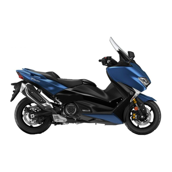
TMAX XP530E-A 2017
Yamaha TMAX XP530E-A 2017 Manuals
Manuals and User Guides for Yamaha TMAX XP530E-A 2017. We have
1
Yamaha TMAX XP530E-A 2017 manual available for free PDF download: Service Manual
Yamaha TMAX XP530E-A 2017 Service Manual (677 pages)
Brand:
Yamaha
| Category:
Motorcycle
| Size: 55.75 MB
Table of Contents
Important
4
Important Manual Information
4
Symbols
6
Table of Contents
7
General Information
9
Model Label
10
Vehicle Identification Number
10
Aims and Advantages of Using YCC-T
11
Features
11
Mechanism Characteristics
11
YCC-T (Yamaha Chip Controlled Throttle)
11
YCC-T System Outline
12
OUTLINE of the CRUISE CONTROL SYSTEM (for XP530D-A)
13
Activating and Setting the Cruise Control System
14
Adjusting the Set Cruising Speed
14
Automatic Deactivation of the Cruise Control System
15
Deactivating the Cruise Control System
15
Turning off the Cruise Control System
15
Using the Resume Function
15
Meter Displays During Cruise Control System Operation
16
Self-Diagnosis Device
16
OUTLINE of the TCS (Traction Control System)
18
TCS (Traction Control System) Layout
18
TCS (Traction Control System) Block Diagram
19
Resetting the Traction Control System
20
Setting the Traction Control System
20
Traction Control System
20
Coolant Temperature Meter
21
Eco Indicator
21
Fuel Meter
21
Multi-Function Display
21
Drive Mode Display (XP530-A, XP530D-A)
22
Function Display
22
Oil Change Indicator “Oil”
22
V-Belt Replacement Indicator “V-Belt”
22
Adjusting the Grip Warmer
23
Adjusting the Seat Heater
23
To Increase the Grip Warmer Temperature
23
To Increase the Seat Heater Temperature
23
Average Fuel Consumption
24
Estimated Traveling Range
24
Grip Warmer Settings
25
Instantaneous Fuel Consumption
25
Setting Mode
25
Seat Heater Settings
26
Traction Control System Settings
26
Resetting the Maintenance Counters
27
Selecting the Units
27
Selecting the Display Items
28
Meter Panel Brightness
29
Setting the Clock
29
To Exit the Setting Mode
30
Bearings and Oil Seals
31
Gaskets, Oil Seals and O-Rings
31
Important Information
31
Lock Washers/Plates and Cotter Pins
31
Preparation for Removal and Disassembly
31
Replacement Parts
31
Circlips
32
Rubber Parts
32
Basic Service Information
33
Quick Fasteners
33
Electrical Parts Handling
34
Electrical System
34
Checking the Electrical System
35
Checking the Connections
36
Special Tools
38
Specifications
47
General Specifications
48
Engine Specifications
49
Chassis Specifications
54
Electrical Specifications
56
General Tightening Torque Specifications
58
Tightening Torques
58
Chassis Tightening Torques
59
Engine Tightening Torques
59
Front Wheel Axle Pinch Bolt
60
Lower Ring Nut
60
Engine
61
Lubrication Points and Lubricant Types
61
Chassis
62
Engine Oil Lubrication Chart
64
Lubrication System Chart and Diagrams
64
Lubrication Diagrams
66
Cooling System Diagrams
74
Cable Routing
78
Headlight Stay (Front View)
78
Front Cowling Assembly (Rear View)
80
Frame (Right Side View)
82
Frame (Left Side View)
86
Rear Frame (Left Side View)
88
Frame (Top View)
92
Handlebar (Top and Left Side View) (for XP530E-A/XP530-A)
96
Handlebar (Front View) (for XP530E-A/XP530-A)
98
Handlebar (Top and Left Side View) (for XP530D-A)
100
Handlebar (Front View) (for XP530D-A)
102
Front Brake (Front, Left Side and Right Side View)
104
Rear Brake (Right Side View)
108
Fuel Tank (Right Side View)
110
Fuel Tank (Left Side View)
112
Fuel Tank (Top View)
114
Air Filter Case and Throttle Body (Left Side View)
116
Radiator (Right Side View)
118
Radiator (Left Side View)
120
Radiator (Top View)
122
Hydraulic Unit Assembly (Top and Front View)
124
Periodic Checks and Adjustments
127
General Maintenance and Lubrication Chart
129
Introduction
129
Periodic Maintenance Chart for the Emission Control System
129
Checking the Fuel Line
132
Checking the Vehicle Using the Yamaha Diagnostic Tool
132
Adjusting the Valve Clearance
133
Checking the Spark Plugs
133
Checking the Engine Idling Speed
137
Synchronizing the Throttle Bodies
137
Adjusting the Throttle Body Synchronization
138
Checking the Exhaust System
139
Checking the Throttle Body Joints
139
Adjusting the Exhaust Gas Volume
140
Checking the Canister
140
Checking the Cylinder Head Breather Hose
140
Cleaning the V-Belt Case Air Filter Element
141
Replacing the Air Filter Element
141
Checking the Brake Operation
142
Adjusting the Front Disc Brake
143
Checking the Brake Fluid Level
143
Adjusting the Rear Disc Brake
144
Checking the Front Brake Hoses
144
Checking the Front Brake Pads
144
Checking the Rear Brake Pads
144
Bleeding the Hydraulic Brake System
145
Checking the Rear Brake Hose
145
Adjusting the Rear Brake Lock Cable
146
Checking the Rear Brake Lock Pads
147
Checking the Tires
147
Checking the Wheels
147
Checking the Drive Belt
149
Checking the Swingarm Operation
149
Checking the Wheel Bearings
149
Drive Belt Tension
149
Adjusting the Drive Belt Tension
150
Lubricating the Drive Pulley and Drive Axle
151
Checking and Adjusting the Steering Head
152
Checking the Chassis Fasteners
153
Checking the Front Fork
153
Checking the Sidestand Switch
153
Lubricating the Sidestand
153
Lubricating the Steering Head
153
ADJUSTING the REAR SHOCK ABSORBER ASSEMBLY (for XP530D-A)
154
Checking the Rear Shock Absorber Assembly
154
Checking the Connecting Arm and Relay Arm
155
Checking the Engine Oil Level
155
Measuring the Engine Oil Pressure
157
Checking the Coolant Level
158
Checking the Cooling System
158
Changing the Coolant
159
Checking and Lubricating the Cables
161
Checking the Brake Light Switches
161
Checking the Throttle Grip
161
Replacing the V-Belt
161
Adjusting the Headlight Beams
162
Checking and Charging the Battery
162
Checking the Fuses
162
Right Headlight
163
Chassis
165
General Chassis
168
Removing the Windshield and Meter Assembly (for XP530D-A)
169
Removing the Front Turn Signal Light and Front Cowling Assembly
170
Removing the Bottom Cowling
171
Removing the Battery and Leg Shield Assembly
172
ADJUSTING the WINDSHIELD HEIGHT (for XP530E-A/XP530-A)
174
General Chassis (1)
174
Removing the Front Cover
174
Installing the Side Panel
175
Removing the Side Panel
175
Removing the Inner Panel
176
Removing the Battery Cover
177
General Chassis (2)
178
Removing the Footboard
178
Removing the Rear Cowling and Mudguard Assembly
179
Removing the Rear Cowling Assembly and Seat Assembly
180
Removing the Storage Box
181
Removing the Footboard
182
Removing the Rear Cover
182
Removing the Side Cover
182
Removing the Rear Cowling
183
General Chassis (3)
184
Removing the Battery Box and ECU (Engine Control Unit)
184
Removing the Electrical Components Tray (for XP530E-A/XP530-A)
185
Removing the Electrical Components Tray (for XP530D-A)
186
Removing the Headlight Stay
187
INSTALLING the WINDSHIELD DRIVE UNIT (for XP530D-A)
188
Front Wheel
189
Disassembling the Front Wheel
190
Checking the Front Wheel
191
Disassembling the Front Wheel
191
Removing the Front Wheel
191
Assembling the Front Wheel
192
Maintenance of the Front Wheel Sensor and Sensor Rotor
193
Adjusting the Front Wheel Static Balance
194
Installing the Front Wheel (Disc Brake)
195
Removing the Rear Wheel
198
Removing the Rear Brake Disc and Rear Wheel Pulley
199
Disassembling the Rear Wheel Assembly
200
Disassembling the Rear Wheel
201
Removing the Rear Wheel
201
Assembling the Rear Wheel
202
Checking and Replacing the Rear Wheel Pulley
202
Checking the Rear Wheel Drive Hub
202
Adjusting the Rear Wheel Static Balance
203
Installing the Rear Wheel (Disc Brake)
203
Maintenance of the Rear Wheel Sensor and Sensor Rotor
203
Front Brake
207
Removing the Front Brake Pads
207
Removing the Front Brake Master Cylinder
208
Disassembling the Front Brake Master Cylinder
209
Removing the Front Brake Calipers
210
Disassembling the Front Brake Calipers
211
Checking the Front Brake Discs
212
Introduction
212
Replacing the Front Brake Pads
213
Removing the Front Brake Calipers
214
Assembling the Front Brake Calipers
215
Checking the Front Brake Calipers
215
Installing the Front Brake Calipers
216
Assembling the Front Brake Master Cylinder
217
Checking the Front Brake Master Cylinder
217
Installing the Front Brake Master Cylinder
217
Rear Brake
220
Removing the Rear Brake Pads
220
Removing the Rear Brake Master Cylinder
221
Disassembling the Rear Brake Master Cylinder
222
Removing the Rear Brake Caliper
223
Disassembling the Rear Brake Caliper
224
Removing the Rear Brake Lock Pads
225
Removing the Rear Brake Lock Caliper
226
Disassembling the Rear Brake Lock Caliper
227
Checking the Rear Brake Disc
228
Introduction
228
Replacing the Rear Brake Pads
228
Removing the Rear Brake Caliper
229
Checking the Rear Brake Caliper
230
Assembling the Rear Brake Caliper
231
Installing the Rear Brake Caliper
231
Assembling the Rear Brake Master Cylinder
232
Checking the Rear Brake Master Cylinder
232
Installing the Rear Brake Master Cylinder
232
Replacing the Rear Brake Lock Pads
234
Replacing the Rear Brake Lock Cable
235
Assembling the Rear Brake Lock Caliper
236
Checking the Rear Brake Lock Caliper
236
Installing the Rear Brake Lock Caliper
237
ABS (Anti-Lock Brake System)
238
Abs Components Chart
239
Checking the Hydraulic Unit Assembly
240
Removing the Hydraulic Unit Assembly
240
Installing the Hydraulic Unit Assembly
241
Hydraulic Unit Operation Test
242
Checking the Abs Warning Light
245
Handlebar
246
Removing the Handlebar Cover
246
Removing the Handlebar Switch and Throttle Grip
247
Checking the Handlebar
250
Installing the Handlebar
250
Adjusting the Accelerator Position Sensor
252
Front Fork
254
Removing the Front Fork Legs
254
Disassembling the Front Fork Legs
255
Disassembling the Front Fork Legs
256
Removing the Front Fork Legs
256
Checking the Front Fork Legs
257
Assembling the Front Fork Legs
258
Installing the Front Fork Legs
262
Removing the Lower Bracket
263
Steering Head
263
Checking the Steering Head
265
Removing the Lower Bracket
265
Installing the Steering Head
266
Belt Drive
267
Removing the Drive Belt
267
Checking the Drive Belt
268
Installing the Drive Pulley Assembly
268
Rear Shock Absorber Assembly
269
Removing the Rear Shock Absorber Assembly
269
Disposing of a Rear Shock Absorber
270
Removing the Rear Shock Absorber Assembly
270
Assembling the Connecting Arm
271
Checking the Connecting Arm and Relay Arm
271
Checking the Rear Shock Absorber Assembly
271
Installing the Relay Arm
271
Installing the Rear Shock Absorber Assembly
272
Removing the Swingarm
273
Swingarm
273
Checking the Swingarm
275
Installing the Swingarm
275
Engine
277
Engine Inspection
280
Measure the Compression Pressure
280
Engine Removal
281
Removing the Exhaust Assembly
281
Disconnecting the Leads
282
Removing the Engine
284
Installing the Engine
285
Camshafts
286
Removing the Cylinder Head Cover
286
Removing the Camshafts
287
Removing the Camshafts
288
Checking the Camshafts
289
Checking the Camshaft Sprockets
290
Checking the Timing Chain Guides
290
Checking the Timing Chain Tensioner
290
Installing the Camshafts
291
Cylinder Head
294
Removing the Cylinder Head
294
Checking the Cylinder Head
295
Installing the Cylinder Head
295
Removing the Valves and Valve Springs
297
Valves and Valve Springs
297
Checking the Valves and Valve Guides
298
Removing the Valves
298
Valves and Valve Springs
298
Checking the Valve Seats
300
Checking the Valve Springs
301
Checking the Valve Lifters
302
Installing the Valves
302
Cylinder and Pistons
304
Removing the Cylinder and Pistons
304
Checking the Cylinders and Pistons
305
Removing the Piston
305
Checking the Piston Rings
306
Checking the Piston Pins
307
Installing the Piston and Cylinder
307
Electric Starter
309
Removing the Starter Motor
309
Disassembling the Starter Motor
310
Checking the Starter Motor
311
Assembling the Starter Motor
312
Installing the Starter Motor
312
Removing the V-Belt Case Cover
313
V-Belt Automatic Transmission
313
Removing the V-Belt and Primary/Secondary Sheave
314
Disassembling the Primary Sheave
315
Disassembling the Secondary Sheave
316
Disassembly the Secondary Sheave
317
Removing the Primary Sheave and Secondary Sheave
317
Checking the Primary Sheave Weights
318
Checking the Secondary Sheave
318
Checking the Sliders
318
Checking the V-Belt Case Air Duct
318
Assembling the Primary Sheave
319
Assembling the Secondary Sheave
319
Installing the Primary Sheave Assembly, Secondary Sheave Assembly and V-Belt
320
Installing the V-Belt Case
322
Generator and Starter Clutch
323
Removing the Generator Rotor and Starter Clutch
324
Removing the Stator Coil and Oil Tank
325
Checking the Starter Clutch
326
Removing the Generator
326
Removing the Starter Clutch
326
Assembling the Oil Tank
327
Checking the Oil Strainer
327
Installing the Starter Clutch
327
Installing the Generator
328
Clutch
330
Removing the Clutch
330
Disassembling the Clutch
331
Disassembling the Clutch
333
Removing the Clutch
333
Checking the Clutch Damper Springs
334
Checking the Clutch Spring Plate
334
Checking the Friction Plates
334
Assembling the Clutch
335
Checking the Clutch Boss
335
Checking the Clutch Housing
335
Checking the Clutch Springs
335
Checking the Pressure Plate and Thrust Plate
335
Installing the Clutch
337
Oil Pump
338
Removing the Oil Pump Assembly
338
Disassembling the Oil Pump Assembly
339
Assembling the Oil Pump
340
Checking the Oil Pump Drive Chain
340
Checking the Relief Valve
340
Installing the Oil Pump
340
Crankcase
341
Separating the Crankcase
341
Removing the Oil Seals and Bearings
343
Assembling the Crankcase
344
Checking the Crankcase
344
Checking the Timing Chain
344
Disassembling the Crankcase
344
Crankshaft
346
Removing the Crankshaft Assembly
346
Removing the Connecting Rods
347
Checking the Crankshaft and Connecting Rods
348
Removing the Crankshaft Journal Bearings
348
Installing the Connecting Rods
352
Installing the Crankshaft Journal Bearings
352
Installing the Crankshaft Assembly
354
Removing the Transmission
356
Transmission
356
Checking the Transmission
357
Cooling System
359
Radiator
360
Removing the Radiator
360
Checking the Radiator
362
Installing the Radiator
362
Oil Cooler
364
Removing the Oil Cooler
364
Checking the Oil Cooler
365
Installing the Oil Cooler
365
Removing the Thermostat
366
Thermostat
366
Checking the Thermostat
367
Installing the Thermostat Assembly
367
Removing the Water Pump
368
Water Pump
368
Disassembling the Water Pump
369
Assembling the Water Pump
370
Checking the Water Pump
370
Installing the Water Pump
371
Fuel System
373
Removing the Fuel Tank
374
Removing the Rollover Valve and Canister
375
Checking the Rollover Valve
376
Checking the Fuel Pump Body
376
Checking the Fuel Pump Operation
376
Removing the Fuel Pump
376
Installing the Fuel Pump
377
Installing the Fuel Tank
377
Throttle Body
378
Removing the Air Filter Case
378
Removing the Throttle Body
379
Disassembling the Throttle Body Assembly
381
Checking and Cleaning the Throttle Bodies
382
Removing the Injectors
382
Removing the Fuel Hose
382
Checking the Injectors
382
Replacing the Throttle Bodies
384
Installing the Injectors
384
Checking the Injector Pressure
384
Checking the Fuel Pressure
385
Installing the Fuel Hose (Fuel Rail Side)
386
Adjusting the Throttle Position Sensor
386
Electrical System
389
Ignition System
392
Electric Starting System
400
Starting Circuit Cut-Off System Operation
406
The Starter Motor Fails to Turn
408
Charging System
410
Lighting System
418
Signaling System
426
Checking the Signaling System
433
The Horn Fails to Sound
433
The Tail/Brake Light Fails to Come on
433
Turn Signal Light, Turn Signal Indicator Light or both Fail to Blink
433
The Fuel Meter Fails to Operate
434
The Coolant Temperature Meter Fails to Operate
434
The Speedometer Fails to Operate
434
The V-Belt Replacement Indicator Fails to Come on
435
The Ambient Temperature Meter Fails to Operate
435
The Tachometer Fails to Operate
435
The Oil Change Indicator Fails to Come on
436
The Buzzer Does Not Sound
436
Ecu Self-Diagnostic Function
452
Checking the Engine Trouble Warning Light
452
ECU Detects an Abnormal Signal from a Sensor
452
Yamaha Diagnostic Tool
453
Features of the Yamaha Diagnostic Tool
453
Functions of the Yamaha Diagnostic Tool
453
Parts Connected to the ECU
454
Troubleshooting Details (Fault Code)
454
Connecting the Yamaha Diagnostic Tool
454
Fault Code No. P0030
455
Fault Code No. P0107, P0108
457
Fault Code No. P0112, P0113
462
P0112, P0113
463
Fault Code No. P0122, P0123, P0222, P0223, P2135
469
P0122, P0123, P0222, P0223, P2135
470
Fault Code No. P0132
475
Fault Code No. P0507
483
Fault Code No. P0560
484
Fault Code No. P062F
485
Fault Code No. P0657
488
Fault Code No. P2122, P2123, P2127, P2128, P2138
496
Fault Code No. P2195
504
Fault Code No. U0155 or “Err”
506
Cruise Control System
508
Cruise Control Circuit Operation
510
Basic Instructions for Troubleshooting
512
Basic Process for Troubleshooting
513
Fault Code Table
514
Checking the Cruise Control System Indicator Light
514
Diagnosis Using the Fault Codes
514
Diagnosis Using the Malfunction History Codes
524
Malfunction History Is Not Displayed
524
Deleting the Fault Codes
524
Final Check
524
Fuel Pump System
526
If the Fuel Pump Fails to Operate
532
Windshield Drive System
534
The Windshield Fails to Move
536
Grip Warmer System
538
The Grip Warmers Do Not Become Warm at All
540
The Grip Warmers Are Abnormally Hot While the Engine Is Idling
541
The Grip Warmers Do Not Become very Warm While Vehicle Is Traveling
541
The Temperature Levels of the Grip Warmer Settings Cannot be Changed
541
Seat Heater System
542
The Seat Heater Do Not Become Warm at All
544
The Seat Heater Is Abnormally Hot While the Engine Is Idling
545
The Seat Heater Do Not Become very Warm While the Vehicle Is Traveling
545
The Temperature Levels of the Seat Heater Settings Cannot be Changed
546
Abs Coupler Location Chart
556
ABS Operation When the ABS Warning Light Comes on
558
Checking the ABS ECU
558
Abs Troubleshooting Outline
558
Maintenance of the Abs Ecu
558
Self-Diagnosis and Servicing
559
Self-Diagnosis Using the ABS ECU
559
Special Precautions for Handling and Servicing Vehicle Equipped
559
Only the Abs Warning Light Fails to Come on
561
All Indicator Lights Fail to Come on
561
The Abs Warning Light Comes on
561
Malfunction Are Currently Detected
562
Abs Ecu and Fi Ecu Fail to Communicate
562
Only the Abs Ecu Fails to Communicate
562
Fault Code No. 12
568
Fault Code No. 13, 26
568
Fault Code No. 14, 27
569
Fault Code No. 15
570
Fault Code No. 16
571
Fault Code No. 17, 45
572
Fault Code No. 21
573
Fault Code No. 24
573
Fault Code No. 33
574
Fault Code No. 32
574
Fault Code No. 31
574
Fault Code No. 34
575
Fault Code No. 41
575
Fault Code No. 42, 47
576
Fault Code No. 43
577
Fault Code No. 44
577
Fault Code No. 51, 52
578
Fault Code No. 53
578
Fault Code No. 56
579
Fault Code No. 55
579
Fault Code No. 54
579
Fault Code No. 63
580
Fault Code No. 64
581
Smart Key System
584
Checking the Vehicle Power
590
Checking the Smart Key System
591
Engine Does Not Start Even Though Vehicle Power Is Turned on
592
Seat/Fuel Lid Does Not Open. (Vehicle Power Is Turned On.)
592
Storage Compartment Lid (for XP530-A/XP530D-A) Does Not Open
593
The Turn Signal Light Fails to Blink (Parking Mode Operation)
594
Centerstand Does Not Unlock. (Vehicle Power Is Turned On.)
594
Smart Key System Self-Diagnosis
596
Smart Key System Emergency Mode
598
Registering a Smart Key
600
Disabling a Smart Key
601
Replacing the Remote Control Unit, Steering Lock, and Ecu
602
Replacing the Remote Control Unit
602
Replacing the Steering Lock Unit
602
Replacing the Ecu
602
Replacement Parts List
603
Electrical Components
606
Checking the Switches
612
Checking the Bulbs and Bulb Sockets
619
Checking the Condition of the Bulbs
619
Charging Method Using a Variable-Current (Voltage) Charger
623
Checking the Relays
624
Starter Relay
624
Starting Circuit Cut-Off Relay
624
Headlight Relay (Dimmer)
625
Radiator Fan Motor Relay
625
Fuel Injection System Relay
625
Ignition System Relay
626
Turn Signal/Hazard Relay
626
Steering Lock Relay
626
Sidestand Relay
626
Brake Light Relay (for XP530D-A)
627
Windshield Drive Unit Relay (Down)
627
Windshield Drive Unit Relay (Up)
627
Seat Heater Relay (Control) (for XP530D-A)
628
Seat Heater Relay (Power) (for XP530D-A)
628
Smart Key System Relay (Unlock)
628
Smart Key System Relay (Lock)
629
Checking the Diodes
630
Checking the Spark Plug Caps
631
Checking the Ignition Coil
632
Checking the Ignition Spark Gap
632
Checking the Lean Angle Sensor
633
Checking the Crankshaft Position Sensor
633
Checking the Starter Motor Operation
634
Checking the Stator Coil
634
Checking the Rectifier/Regulator
634
Checking the Fuel Sender
635
Checking the Fuel Meter/Fuel Level Warning Indicator
635
Checking the Radiator Fan Motor
636
Checking the Coolant Temperature Sensor
636
Checking the Throttle Position Sensor
637
Checking the Accelerator Position Sensor
637
Checking the Throttle Servo Motor
638
Checking the Windshield Drive Unit
638
Checking the Grip Warmers
639
Checking the Intake Air Pressure Sensor
639
Checking the Seat Heater
639
Checking the Intake Air Temperature Sensor
640
Checking the Fuel Injector
640
Checking the Seat/Fuel Lid Lock Solenoid
641
Checking the Smart Key Battery
641
Checking the Buzzer
641
Checking the Storage Compartment Lid Lock Solenoid
642
Troubleshooting
643
Starting Failure/Hard Starting
644
Self-Diagnostic Function and Diagnostic Code Table (Ecu)
648
Self-Diagnostic Function Table (for Fuel Injection System)
648
Event Code Table
660
Troubleshooting Details (Event Code)
662
Event Code No. 30
662
Event Code No. 70
663
Wiring Diagram
665
Advertisement
Advertisement
Related Products
Yamaha XP530E-A
Yamaha XP530D-A
Yamaha TMAX XP530-A 2017
Yamaha TMAX XP530D-A 2017
Yamaha Tmix XP500Y
Yamaha Tmax XP500 2016
Yamaha XP560EL
Yamaha TMax XP500A 2012
Yamaha TMAX XP560DR
Yamaha TMax XP500 2012
Yamaha Categories
Motorcycle
Musical Instrument
Electronic Keyboard
Receiver
Amplifier
More Yamaha Manuals
Login
Sign In
OR
Sign in with Facebook
Sign in with Google
Upload manual
Upload from disk
Upload from URL