Sign In
Upload
Manuals
Brands
XY Powersports Manuals
Utility Vehicle
XY500UTV
XY Powersports XY500UTV Manuals
Manuals and User Guides for XY Powersports XY500UTV. We have
1
XY Powersports XY500UTV manual available for free PDF download: Service Manual
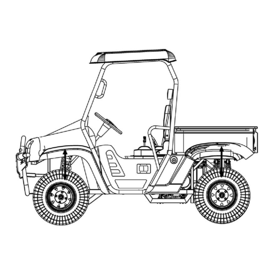
XY Powersports XY500UTV Service Manual (260 pages)
Brand:
XY Powersports
| Category:
Utility Vehicle
| Size: 16.62 MB
Table of Contents
Table of Contents
3
Important Safety Precautions
4
Service Information
4
A few Words about Safety
4
Conversion Table
5
Identification Number Records
6
Main Data Table
7
Overhaul Datasheet
9
Lubricating Device
9
Air Inlet System
10
Cooling Device
10
Front/Rear Wheel
10
Cables, Pipes, Cable Routing
16
Tightening Torque
22
Vehicle Body,Muffler
22
Operation Cautions
22
Overhaul Information
22
Center Cover, Steering Wheel
23
Decorate Cover, Steering Stem
23
Vehicle Body, Muffler
23
Holder, Meter
24
Front Side Support(LH)
26
Front Side Support (RH)
26
Front Vent Cover
26
Seat, Driver
27
Seat, Passenger
27
Gearshift Knob
28
Decorate Cover,Gearshift
28
Gearshift Unit
28
Handle, Parking Brake
29
Skid Plate (L)
29
Rear Fender (L)
30
Rear Fender(R)
30
Fender, Cargo Box(L)
30
Cargo Box
31
Fender, Cargo Box
31
Side Door (LH)
32
Side Door (RH)
32
Bumper
33
Fuel Tank
33
Headrest, Driver
34
Headrest, Passenger
34
Backrest, Passenger (500L/500UEL)
34
Safety Belt, Driver
35
Safety Belt, Passenger
35
Safety Belt Fastener
35
Rear Mirror (RH)
36
Rear Mirror(LH)
36
Roll-Over Bar(500UTV/500UE)
36
Roll-Over Bar(500LUTV/500UEL)
37
Bumper Protector
38
Winch Cable and Motor
38
Muffler
40
Description of Visible Parts
41
Inspection & Adjustment
42
Overhaul Info
42
Replace Parts Regularly
42
Regular Maintenance Table
43
Inspection & Adjustment
43
Steering Stem
47
Brake Disc, Brake Pad
48
Change the Brake Fluid
48
Master Cylinder
48
Front Toe-In Size
49
Wheels
49
Tire Pressure
50
Tire Tread
50
Lift the Front Wheel
51
Suspension System
51
Sway of Wheel Bearing
51
Wheel Nut and Wheel Axle
51
Adjusting the Absorber
52
Fuel Device
52
Gear Shifting
52
Throttle Pedal Check
53
Valve Clearance
54
Engine Idle Speed
55
Spark Plug
55
Air Filter
56
Spark Plug Gap
56
Drive Belt
57
Special Tool: Rotor Holder
57
Check Engine Oil Level
59
Inspection of Lubrication System
59
Replacing Engine Oil
59
Inspection of External Oil Pipe
60
Replacing Oil Filter
60
Tool: Oil Filter Wrench
60
Inspection of Cooling System
61
Replacing Coolant
61
Inspection of Radiator Hose
62
Testing Cylinder Pressure
62
Inspection of Oil Pressure
63
Oil Pressure Is too High
63
Oil Pressure Is too Low
63
Testing Oil Pressure
63
Clutch Lock-Up Inspection
64
Initial Engagement Inspection
64
Inspection of Clutch Engagement and Lock-Up
64
Cooling and Lubricatiing System
65
Cooling System Illustration
66
Engine Coolant
67
Inspection of Cooling Circuit
67
Inspection and Cleaning of Radiator and Water Hoses
68
Radiator Cap
68
Radiator Hose Inspection
68
Radiator Inspection and Cleaning
68
Inspection of Fan Motor
69
Inspection of Thermoswitch
69
Inspection of Thermostat
70
Inspection of Water Temperature Sensor
70
Water Temperature and Resistance
70
Water Temperature Sensor
70
Water Pump
71
Mechanical Seal
73
Inspection of Water Pump
73
Bearing
73
Oil Seal
74
Water Pump Body
74
Impeller
74
Assembly and Installation of Water Pump
74
Removal of Engine, Transmission System and Gearshift
79
Inspection Information
79
Disassembly Engine
80
Cvt
82
Installation of Engine
83
Installation
85
Gearshift
85
Engine Removal/Installation Orders and the Relative Page Numbers
86
Engine Removal
87
Left Side Cover
87
Recoil Starter
87
Inspection Plug
87
Cylinder Head Cover
88
Timing Chain Tensioner
88
Camshaft
88
Cylinder Head
89
Cylinder
89
Starting Motor
90
Oil Filter
91
Tool: Oil Filter Remover
91
Sector Gear
91
Sheave Drum
92
Left Crankcase Cover
92
Magneto Rotor
92
Starting Motor Gear
93
Oil Pump Sprocket and Chain
93
CVT Cover
94
Cvt(Continuously Variable Transmission)
94
Timing Chain
95
Clutch
95
CVT Case
95
Driven Bevel Gear, Front Output Shaft
96
Engine Center
96
Gear Position Bolt
96
Shift Cam, Fork/Shaft
97
Drive Bevel Gear
97
Drive Shaft, Drive Shaft
97
Balancer Shaft
97
Crankshaft
98
Oil Bump, Relief Valve
98
Rocker Arm Shaft
99
Cylinder Head Cover Distortion
99
Engine Components Inspection
99
Rocker Arm
100
Cylinder Head Distortion
102
Valve Seat Width
102
Valve Stem and Valve Guide
102
Valve Stem O.D
103
Valve Stem Run-Out
103
Valve Head Radial Run-Out
103
Valve Face Wear
103
Valve Spring
104
Assembly of Cylinder Head
104
Camshaft Journal Wear
107
Automatic Decompression
107
Cam Wear
107
Camshaft Journal O.D.
108
Camshaft Run-Out
108
Timing Sprocket and Chain
108
Tensioner and Chain Guide
108
Chain Tensioner Inspection
109
Cylinder Distortion
109
Cylinder Bore
109
Piston
110
Piston Diameter
110
Piston Ring to Groove Clearance
110
Piston Ring Free End Gap and End Gap
111
Piston Pin and Pin Bore
111
Connecting Rod/Crankshaft
112
Connecting Rod Deflection
112
Connecting Rod Big End Side Clearance
112
Crankshaft Run-Out
112
Clutch Shoes
113
Clutch Wheel
113
Primary and Secondary Sheave
114
Primary Sliding Sheave
115
Primary Sliding Sheave and Fixed Sheave
116
Install Spacer
117
Secondary Sheave
117
O-Ring and Oil Seal
118
Secondary Sheave Spring
119
Secondary Sliding and Fixed Sheave
119
Assembly
119
Transmission
122
Oil Pump
126
Oil Strainer
127
Relief Valve
127
Bevel Gear Washer Adjustment
128
Driven Bevel Gear
128
Front Output Shaft
128
Bevel Gear
129
Bevel Gear Backlash
129
Tooth Contact
130
Electric Starter Gear
133
Crankcase
137
Engine Assembly
138
Oil Pump and Relief Valve
138
Connecting Rod
139
Shift Cam, Shift for
140
Right Crankcase
140
Carburetor、Fuel System, Air Intake System
155
Overhaul Info
156
Carburetor Removal
157
Inspection
158
Measurement and Adjustment
159
Carburetor Assembly
160
Fuel Level
160
Carburetor Installation
161
Carburetor Parameters
161
High Pressure Fuel Line Installation
162
Throttle Body Disassembly
162
Fuel Injector Assy Disassembly
162
High Pressure Fuel Line Disassembly
162
Fuel Injector Assy Removal
163
Fuel Injector Assy Assembly
163
Idle Air Control Valve Disassembly
163
Idle Air Control Valve Installation
163
Overhaul Information Operating Cautions Notes
164
Maintenance Standard
164
Wheel Cannot Turn Freely
165
Troubleshooting Heavy
165
Vibration of Front Wheel
165
Shaking Steering Wheel
165
Front Wheel, Front Brake, Suspension, Steering
165
Front Wheel
166
Inspection Rim
166
Front Wheel Hub
166
Brake System
167
Front Brake Caliper
167
Brake Disc
168
Front Brake Master Cylinder
168
Brake Pedal Removal
169
Front Left Suspension
170
Front Suspension
171
Rocket Arm
172
Front Right Arm
172
Ball Pin
173
Right Steering Knuckle
173
Constant Velocity Drive Shaft
174
Left Constant Velocity Drive Shaft, Front Axle
174
Steering System
175
Rear View Mirror
176
Installation of Combination Switch
178
Installation of Rear View Mirror
179
Installation of Steering
179
Install Steering Wheel
179
Rear Wheel, Rear Brake, Suspension
181
Rear Wheel Wobbles
182
Rear Shock Absorber Is too Soft
182
Rear Shock Absorber Is too Hard
182
Poor Brake Efficiency
182
Rear Wheel Removal
183
Wheel Hub Removal
183
Rear Drive Shaft
184
Parking Caliper
184
Inspection Brake Disc
184
Rear Brake Caliper
184
Rear Suspension System
185
Rear Right Suspension
185
Stabilizer Bar
186
Right Rear Absorber
186
Rear Right Arm
186
Rear Left Suspension
186
Front/Rear Axle Overhaul Information
187
Inspection & Overhaul
188
Observation and Judgement
188
Front and Rear Axle
188
Disassembly of Front Axle
189
Inspection after Front Axle Disassembly
190
Front Axle Assembly and Adjustment
191
Front Axle Case Cover Assembly
191
Front Differential Gear Case Cover
191
Differential Gear Assembly
191
Disassembly of Rear Axle
194
Needle Bearing Removal
195
Rear Axle Inspection after Disassembly
195
Rear Axle Assembly and Adjustment
196
Electric System
198
Charging Circuit Diagram
199
Charging System
199
Magneto Coil Resistance
199
Magnetor Non-Loaded Performance
199
Adjust Multimeter to Diode
200
Starting System
201
Trigger Circuit Diagram
201
Armature Coil
202
Commutator
202
Electric Brush
202
Initiating Relay
203
Fule Pump Output Port Pressure
204
Starting Engine Notice
204
Ecu
205
Electronic Fuel Injection System
205
Engine Electronic Fuel Injection System
205
Inlet Pressure Sensor
205
Throttle Position Sensor
205
Service Tools
207
Electronic Fuel Injection Parts
209
Each Pin Funtion
210
Throttle Valve Assy
210
MAP Sensor
211
Intake Air Temperatur Sensor
212
Water Temperature Sensor
213
Oxygen Sensor
214
The Pins Function
214
Trigger
215
Odometer Sensor
216
Odometer Sensor Testing
216
Functions of the Foots
217
Gear Sensor Cluster
217
Reverse Gear Assemble
217
Fuel Pump Assy
218
Fuel Injector
219
Fuel Injector Installation
219
Oil Atomizer
219
Idle Air Control
220
Idle Speed Control Valve
220
Ignition Coil
221
Ignition Coil Parameter List
221
Measuring Secondary Ignition
221
Diagnostic Equipment
222
Fault Self-Diagnosis
222
Trouble Code List
223
Lighting and Switches
226
Head Light Cannot Turn on
227
Troubleshooting
227
Replacing Bulb
228
Headlight Bulb
228
Inspection of Headlight
228
Brake Light/Tail Light Bulb
229
Front Turning Indicator Bulbs
229
Rear Turning Indicator Bulbs
229
Dashboard Lighter Bulb
230
Dashboard Indicator Bulb
230
Headlight
230
Ignition Switch
231
Combined Switch
232
Horn
233
Brake Light Switch
233
Horn Button
233
Fuel Sensor (Carbureter)
234
Inspection of Fuel Gauge
235
Water Temperature Transducer
235
Install Transducer
235
Engine Troubleshooting
237
Diagnosis Troubles According to EFI System Trouble Code
240
Trouble Code: P0030 Oxygen Sensor Heating Control Circuit Broken
241
Trouble Code: P0031 Oxygen Sensor Heating Circuit Short to Ground
241
Trouble Code: P0032 Oxygen Sensor Heating Circuit Short to Power
241
Trouble Code:p0053 Inner Resistance of Oxygen Sensor Heating Not Correct
241
Trouble Code:p0112 Air Inlet Temperature Sensor Signal Voltage Low.
242
Trouble Code:p0107 Low Voltage of Air Inlet Pressure Sensor Circuit
242
Trouble Code:p0106 Air Inlet Pressure Sensor Signal Irrationally Failure
242
Trouble Code:p0108 High Voltage of Air Inlet Pressure Sensor Circuit
242
Trouble Code: P0117 Engine Water Temperature Sensor Circuit Voltage Low.
243
Trouble Code: P0118 Engine Water Temperature Sensor Circuit Voltage High.
243
Trouble Code: P0123 Voltage O F Throttle Control Positioning Sensor Circuit Higher than the Higher Limit
243
Trouble Code: P0130 Oxygen Sensor Signal Irrationally Failure
243
Trouble Code: P0132 Oxygen Sensor Circuit Voltage High
244
Trouble Code: P0133 Oxygen Sensor Aging
244
Trouble Code: P0134 Oxygen Sensor Signal Failure
244
Trouble Code: P0201 Cylinder Injector Control Circuit Open
244
Errors Coding: P0444 Control Circuit Voltage of Idle Air Control Valve Open Circuit
245
Errors Coding: P0261 Control Circuit of Single Cylinder Injector Short to Ground
245
Errors Coding: P0322 Non-Rotate Speed Sensor Pulse Signal (Short Circuit or Open
245
Errors Coding: P0262 Control Circuit of Single Cylinder Injector Short Circuit
245
Errors Coding: P0458 Control Circuit Voltage of Idle Air Control Valve too Low
246
Errors Coding: P0459 Control Circuit Voltage of Idle Air Control Valve too High
246
Errors Coding: P0501Speed Sensor Signal Improper.
246
Errors Coding: P0506 Rotate Speed of Idle Air Control Valve Slower than Target Idle Speed
246
Errors Coding: P0507
247
Errors Coding: P0650 MIL Lamp-Driver Circuit Fault
247
Errors Coding: P2177
248
Errors Coding: P2178
248
Diagnosis Troubles According to Engine Fault Phenomena
249
Starting Failure/Hard Starting
250
Engine Can Rotate but Starting Failure
250
Hard Starting in Normal Status
251
Hard Starting in Cold Status
251
Regularly Rotate Speed, but Engine Starting Hard at any Time
252
Engine Works Regularly,But Unsteady Idle Speed at any Time
253
Engine Works Regularly,But Unsteady Idle Speed When Engine Is in Warming-Up
254
Engine Starting Normally, but Idle Speed Unsteady after Warming-Up
255
Engine Starting Regularly, but Idle Speed Is too High
256
Rotate Speed Can Not Increase or Engine Power off When in Acceleration
257
Reaction Slowly When in Acceleration
258
Advertisement
Advertisement
Related Products
XY Powersports XY500LUTV
XY Powersports XY500UE
XY Powersports c
XY Powersports Categories
Utility Vehicle
More XY Powersports Manuals
Login
Sign In
OR
Sign in with Facebook
Sign in with Google
Upload manual
Upload from disk
Upload from URL