Sign In
Upload
Manuals
Brands
Xinje Manuals
Servo Drives
DS2-22P3-A
Xinje DS2-22P3-A Manuals
Manuals and User Guides for Xinje DS2-22P3-A. We have
1
Xinje DS2-22P3-A manual available for free PDF download: User Manual
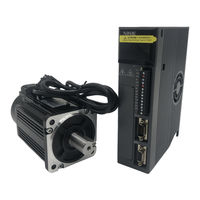
Xinje DS2-22P3-A User Manual (98 pages)
Brand:
Xinje
| Category:
Servo Drives
| Size: 3.81 MB
Table of Contents
Table of Contents
5
Preface
10
1 Checking Product and Part Names
11
Checking Products on Delivery
11
Servomotors
11
Servo Drivers
12
Adaptation Table of Servo Drive and Motor
13
Product Part Names
13
Servomotors
13
Servo Drivers
14
Servomotor
16
Storage Temperature
16
Installation Site
16
Concentricity
16
Orientation
17
Handling Oil and Water
17
Cable Stress
17
Servo Drivers
17
Storage Conditions
17
Installation Site
17
Orientation
18
Installation
18
3 Wiring
20
Main Circuit Wiring
20
Names and Descriptions of Main Circuit Terminal
20
Typical Wiring Example
21
Winding Terminals on Servo Motor
22
I/O Signals
22
Layout of CN0/CN1 Terminals
22
CN0 and CN1
22
I/O Signal Names and Functions
24
Interface Circuits
24
Wiring Encoders
26
Encoder Connections
26
CN2 Encoder Connector Terminal Layout
27
Standard Connection Examples
27
Position Control Mode
28
Communication Port
30
Serial Port 1(COM1)
30
Serial Port 2(COM2)
31
Regenerative Resistor
31
4 Use the Operate Panel
33
Basic Operation
33
Functions of Operate Panel
33
Basic Mode Switching
33
Running Status Mode
34
Monitoring Mode
35
Auxiliary Function
37
Check System Infomation
38
Auxiliary Run Mode
38
Change the Motor Type
39
Check Alarm Information
40
Reset Parameters to Default
40
External Monitoring
40
Parameter Setting
40
Alarm
41
5 Run the Servo System
42
Control Mode Selection
42
Basic Function Setting
42
Servo on Setting
43
Switch the Motor Rotate Direction
43
Overtravel Limit (P-OT & N-OT)
43
Motor Stop Mode When Servo off
45
Power-Off Brake (BK)
45
Position Mode (External Pulse Command)
47
Control Mode Selection
48
Pulse Command
48
Pulse Mode Selection
48
Explanation of Command Pulse
48
Signal Connection
49
Electronic Gear Ratio
49
Parameter
49
Set the Electronic Gear
49
Example of Setting the Electronic Gear
50
Position Command Filter
50
Pulse Error Clear (/CLR)
51
Positioning Complete (/COIN)
51
Positioning Near (/NEAR)
52
Command Pulse Prohibition (/INHIBIT)
52
Position Mode (Internal Position Mode)
53
Control Mode Selection
53
Internal Position Given Mode
53
Position Parameters from Segment 1 to 16
56
Change Step (/CHGSTP)
56
Pause Current Signal (/INHIBIT)
56
Skip Current Signal (/ZCLAMP)
57
Reference Origin
57
Speed Control (Analog Voltage Command)
59
Control Mode Selection
59
Analog Value of Rated Speed
59
Speed Command Offset Auto-Adjustment (F1-03)
60
Proportion Action Command (/P-CON)
60
Zero Clamp (/ZCLAMP)
60
Speed Coincidence Checking (/V-CMP)
61
Torque Limit
61
Internal Torque Limit (Output Torque Max Value Limit)
61
External Torque Limit (Via Input Signal)
61
External Torque Limit (Via Analog Voltage Command)
62
External Torque Limit (Via External Input + Analog Voltage)
62
Output Torque up to Limit Value Signal
63
Soft Start
63
Filter
63
Speed Command Input Dead Voltage
64
Speed Control (Internal Speed)
64
Control Mode Selection
65
Internal Speed Setting
65
Input Signal Setting
65
Speed Control (Pulse Frequency Command)
66
Control Mode Selection
67
Pulse Frequency Command
67
Command Pulse Frequency at Rated Speed
67
Speed Command Pulse Filter Time
67
Torque Control (Analog Voltage Command)
67
Control Mode Selection
68
The Analog Value of Rated Torque
68
Torque Command Offset Autoadjustment (F1-04)
68
Torque Command Filter Time
68
Torque Limit
69
Internal Speed Limit
69
External Speed Limit
69
Speed up to Limit Value Output
69
Torque Command Input Dead Area Voltage
69
Torque Control (Internal Setting)
70
Control Mode Selection
70
Internal Torque Command
70
Switch the Control Mode
70
Other Output Signals
71
ALM and /ALM-RST
71
Warn
71
Rotation Checking (/TGON)
71
Servo Ready (/S-RDY)
71
Encoder Z Phase Output (/Z)
72
AB Phase Feedback Signal of Encoder
72
I/O Signal Distribution
72
Input Signal Distribution
72
Default Setting of Input Terminal
73
Output Terminal Distribution
74
Default Setting of Output Terminal
74
6 Servo Gain Adjustment
75
Servo Gain Setting
75
Gain Setting of Speed Loop
75
Gain Setting of Position Loop
75
Position Loop Proportion Gain
75
Position Loop Feedforward Gain
76
The Experience of Parameter Adjustment
76
Proportion Action Command (P-CON)
76
Gain Switch (G-SEL)
77
7 Specification and Dimension
78
Servo Motor
78
Servo Motor Specification
78
Torque-Speed Feature
80
Servo Motor Dimensions
81
Servo Drivers
84
General Specification
84
Performance Specification
85
Servo Driver Dimensions
86
8 Alarm Information
88
Appendix 1 Parameter List
90
Appendix 2 Application
96
Advertisement
Advertisement
Related Products
Xinje DS2-22P3-AS6
Xinje DS2-22P3-AS
Xinje DS2-20P4-AS
Xinje DS2-20P4-BS6
Xinje DS2-20P7-BSW6
Xinje DS2-21P5-AS
Xinje DS2-20P2
Xinje DS2-21P5
Xinje DS2-20P4-A
Xinje DS2-20P7-A
Xinje Categories
Servo Drives
Control Unit
Controller
Computer Hardware
Network Hardware
More Xinje Manuals
Login
Sign In
OR
Sign in with Facebook
Sign in with Google
Upload manual
Upload from disk
Upload from URL